Numerical Analysis of Refueling Drogue Oscillation During Refueling Docking
2016-09-14ChenLeleLiuXueqiang
Chen Lele,Liu Xueqiang
College of Aerospace Engineering,Nanjing University of Aeronautics and Astronautics,Nanjing 210016,P.R.China(Received 16December 2014;revised 25September 2015;accepted 11October 2015)
with the following values for the constants
1.2 Dynamic grid techniqueThere is flexible deformation of the hose in the numerical implementation in addition to drogue oscillation,which requires the new mesh maintain the same topology and density distribution as the original mesh.Since most dynamic grid deformation techniques are iterative based on the spring analogy without maintaining the primary qualities of the grid,another dynamic grid deformation technique based on Delaunay
Numerical Analysis of Refueling Drogue Oscillation During Refueling Docking
Chen Lele,Liu Xueqiang*
College of Aerospace Engineering,Nanjing University of Aeronautics and Astronautics,Nanjing 210016,P.R.China
(Received 16December 2014;revised 25September 2015;accepted 11October 2015)
Refueling docking at different velocities is simulated by using computational fluid dynamics(CFD)method.The Osher scheme and S-A turbulence model are used to solve the compressible Navier-Stokes equations,and the Delaunay mapping dynamic grid method is also employed.All the numerical results show that the velocity of refueling docking is very important for aerial refueling.When the velocity is lower than 3m/s,the refueling drogue will move upward with obvious cycle staggering,while moving upward with slight cycle staggering at the speed of 3m/s.The results can be referenced by aerial refueling design.
aerial refueling;numerical simulation;refueling drogue;dynamic grid;refueling docking
0 Introduction
Aerial refueling is the process of transferring fuel from one aircraft(the tanker)to another(the receiver)during flight.The procedure allows the receiver aircraft to extend its range and combat radius.Generally,the combat radius of a bomber,a fighter and a transport aircraft can be increased by 25%—30%,30%—40%and 100%,respectively[1].A combat aircraft after extending its range can shift fast over a long distance,and make a sudden strike or strategic defence.Aerial refueling also allows aircrafts to take off with the maximum payload by carrying less fuel and topping up once airborne.Alternatively,a shorter takeoff roll can be achieved because takeoff can be at a lighter weight before refueling once airborne. While increasing the cruise duration,aerial refueling can greatly reduce the number and use intensity of aircrafts,which will relieve potential contradiction and the demand for air force or naval aviation in battle.
The two main refueling systems are probeand-drogue and the flying boom.Generally,the U.S.Air Force uses flying booms,while the Navy and Marines mostly use probe-and-drogue. Each method has its advantages and disadvantages.The probe-and-drogue has simple design and good security whereas the refueling quantity is smaller.The flying boom has higher fuel flow rates but with higher technology requirement and relatively poor security.The probe-and-drogue method is more common in modern air refueling.
The probe-and-drogue method employs a trailing hose with a drogue attachment from the tanker aircraft,the receiver has a probe placed on the aircraft′s nose or fuselage to make the connection.This method is subject to turbulence and aerodynamic forces of the approaching aircraft,which directly affects the aviation safety.Therefore,the analyses of steady aerodynamic characteristics are far from enough.There are a growing number of researches and flight tests on the flow field of the probe-and-drogue at home and abroad,and some results have been achieved[2-5]. Kapseong and James[6]developed a dynamic model of a hose-paradrogue assembly for aerial refueling using the finite-segment approach and studied theeffects of atmospheric turbulence on paradrogue motion by incorporating the Dryden turbulence model into the hose-paradrogue dynamic model. Sriram et al.[7-9]investigated an improved and more natural method of incorporating the trailing vortex effect associated with aircraft flying in close proximities,including the effect of timevarying mass and inertia properties associated with the fuel transfer,the tanker′s vortex induced wind effect and atmospheric turbulence. Eichler[10]presented the derivation and solution of the nonlinear partial differential equation[11]in closed form for sine-wave gust disturbances and numerically for both sine wave,pulse-type vertical gusts and wing vibration,besides,the anticipated effect of vortex from the wingtip on the hose-drogue system was calculated.Hu et al.[12]modeled the trailing refueling hose-drogue by using an array of discrete point mass nodes that represented the physical properties of the hose-drogue,and analyzed the influence of air turbulence on hosedrogue's motion following the simulation of the motion in the cloudless air turbulence.
By utilizing numerical simulation methods,the motion of the refueling drogue in the docking phase of an aerial refueling is simulated and analyzed in this paper,and the movements of the refueling drogue at different velocities are covered as well,which is followed by the generalization of the motion characteristics.
1 Numerical Methods
The numerical methods consist of two parts,one is numerical simulations for unsteady flows,and the other is dynamic grid technique.
1.1 Numerical methods for unsteady flows
The governing equations are Reynolds-averaged Navier-Stokes equations which are solved using finite volume method based on unstructured grids.In addition,S-A one equation turbulence model[13]is adopted.The computing software employed in this paper has own intellectual property right and is verified by many numerical case,which guarantees reliable and rational computa-tion results.
1.1.1 Governingequations
The three-dimensional compressible Reynolds-averaged Navier-Stokes equations can be expressed as

where Uis the conservative variable vector,Fithe inviscid flux vector,and Githe viscous flux vector.They are defined by

whereρ,p,e,Tand kdenote the density,the pressure,the total energy per unit volume,the temperature,and the thermal conductivity coefficient.uiis the velocity component in xidirection and σmithe components of the viscous stress tensor.
1.1.2 Spacialandtemporaldiscretization
The spatial flux terms are discretized by using Osher scheme[14].
Osher's approach assumes that there exist vector-valued functions F+(U)and F-(U)satisfying

and

where the integrals are evaluated along each of the partial integration paths U0,U1/3,U2/3,U1.
The set of equations is then discretized intime by using a fully implicit time discretisation to give

where ndenotes the time level,Rthe flux residual after discretisation that contains all of the terms arising from the spatial discretisation,P=(ρ,u,v,w,p),the primitive variable,and Pn+1= Pn+nΔP.
1.1.3 Turbulencemodel
The turbulence model employs the following S-A one-equation turbulence model

While the left hand side term represents the advection along a streamline,the terms on the right hand side are defined using the following functions

whereνis the molecular viscosity,˜νthe working variable,dthe distance to the closest wall,and S the magnitude of the vorticity.graph[15]is employed in this paper,within which the original grid is mapped back onto the deformed Delaunay graph to provide the new mesh for the new time step or the new design cycle. The method consists of four steps:(1)Generating the Delaunay graph;(2)Locating the mesh points in the graph;(3)Moving the Delaunay graph according to the specified geometric change;(4)Relocating the mesh points in the new graph.The mapping guarantees that the original mesh topology and density distribution are maintained without mesh crossing or overlapping cells.Besides,it is much more efficient,as it requires only non-iterative algebraic calculations. Figs.1,2show the Delaunay graphs and meshes before and after movement,respectively.

with the following values for the constants

1.2 Dynamic grid technique
There is flexible deformation of the hose in the numerical implementation in addition to drogue oscillation,which requires the new mesh maintain the same topology and density distribution as the original mesh.Since most dynamic grid deformation techniques are iterative based on the spring analogy without maintaining the primary qualities of the grid,another dynamic grid deformation technique based on Delaunay

Fig.1 Delaunay graphs

Fig.2 Meshes before and after movement
2 Simulation of Refueling Drogue Movement
In the process of air refueling,the flow field around the receiver aircraft suffers from intense airflow turbulence from both the wing and refueling drogue of the tanker aircraft.When approaching to the refueling drogue,the forward pres-sure from the receiver aircraft breaks the balance of the drogue and make it oscillate.The interaction exacerbates the oscillation and wake influence of refueling drogue on the receiver aircraft,which makes the turbulence from the receiver aircraft winglet couple with the strong airflow between the wing of the tanker aircraft and refueling drogue,thus leading to the drogue to oscillate substantially.The closer the drogue is to the probe on the receiver aircraft,the greater the oscillation amplitude is and the faster the oscillation velocity is.Parameters related to refueling docking,such as docking velocity,distance from the drogue to the probe,oscillation amplitude,oscillation velocity,reel frequency and so on,provide references for pilots to correct and improve flight operations and control over the relative velocity between the two aircrafts.The results of air refueling flight tests indicate that in the docking phase,with the receiver aircraft gradually approaching to the refueling drogue,it is normal for the drogue to escape away from the receiver aircraft due to the effect of forward airflow.Therefore,the docking process should be as short as possible,in addition,right adjustments of both docking velocity and stable flight are critical factors to guarantee the success of refueling docking.
进入系统前,用户需要先登录(用户分为管理员用户和普通用户),登录界面如图2所示。管理员和普通用户对应的权限不同,管理员可操作功能最多,下面以管理员用户登录后进入主界面如图3所示。
The following simplification is made for the simulation:the refueling hose is flexible and does not expected to generate the greater stiff force. The displacement of refueling drogue of a fighter at different docking velocities is then simulated. For convenience,the real-time display is conducted by setting the refueling drogue moving toward the receiver aircraft,and x-axis being docking velocity.Besides,the distances before movement between the receiver and the drogue are 3,0and 0min x,yand zdirections,respectively.The simulations are carried out with docking velocities of 0.6,1.2,2.0and 3.0m/s.The results are displayed in Figs.3—7,where x,yand zstand for the central locations of the refueling drogue.
(1)0.6m/s
The trajectory path of the refueling drogue at the docking velocity of 0.6m/s is shown in Fig.3.

ig.3 Trajectory path of drogue at 0.6m/s
From the results above,it is clear that when docking at the velocity of 0.6m/s,the refueling drogue oscillates with an amplitude of 0.6mand a frequency of 0.5Hz accompanied with an upward movement,as shown in Fig.4.
(2)1.2m/s
Here is the trajectory path of the refueling drogue at the docking velocity of 1.2m/s(See Fig.5).
It is known from the results that when doc-king at the velocity of 1.2m/s,the refueling drogue still oscillates at the frequency of 0.5Hz with an upward movement.Since the docking velocity has doubled,the period of oscillations reduces to one from two.However,there are still many difficulties in the refueling docking because of periodical oscillations.
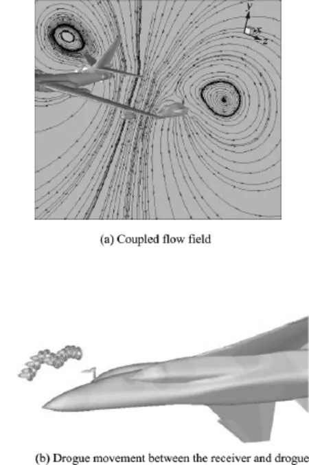
Fig.4 Trajectory path of refueling drogue
(3)2m/s
The results for the refueling drogue at the docking velocity of 2m/s are displayed in Fig.6.
It is clear that the refueling drogue still oscillates at the frequency of 0.5Hz with an upward movement,but the period of oscillations reduces to a half because the docking velocity is three times faster than that of the first case.Besides,the technical difficulties still remain the same with the oscillations of the drogue.
(4)3m/s
Fig.7depicts the trajectory path of the refueling drogue at the docking velocity of 3m/s.
As can be seen from the above results,the refueling drogue will move upward with a drift distance of about 0.6mat the speed of 3m/s,whereas the periodic oscillation is slight.This is mainly because the periodic oscillation is only just beginning after increasing the speed,but does not yet go through 1/4cycle,which makes the oscillation very slight.Therefore,in aerodynamic terms,it is much easier to dock and refuel when the docking velocity is no less than 3m/s.But if the velocity is too fast,the hose will float upward due to the aerodynamic forces,which will break the probe owning to sudden bending moment. Thus,various factors need to be balanced when determining the docking velocity.

ig.5 Trajectory path of drogue at 1.2m/s

Fig.6 Trajectory path of drogue at 2m/s
3 Conclusions
The CFD method and the Delaunay mapping dynamic grid technique are applied to simulate the dynamic behavior of the refueling docking at different velocities varying from 0.6m/s to 3m/s. Compared with other numerical simulation methods,this paper directly simulates the motion between the receiver and the drogue around the coupled flow field,thus being more effective and general.Conclusions can be drawn from numerical simulations and analysis as follows:
(1)When docking at lower velocity,the refueling drogue exhibits periodical oscillations, which makes the refueling docking quite difficult.

g.7 Trajectory path of the drogue at 3m/s
(2)When the docking velocity increases to a certain value,the refueling drogue has little oscillation except upward float,it is then much easier to refuel.
The aerodynamic force transmission and the following response after the instant contact will cause the hose to exhibit interactive coupling phenomenon and backward transverse wave oscillation,which will leave the probe to subject to great bending moment.For this reason,the future work on this research will be carried out combining with structural dynamics.
Acknowledgements
This work is supported by the Funding of Jiangsu In-novation Program for Graduate Education(No.CXLX13_ 133)and the Fundamental Research Funds for the Central Universities.
References:
[1] XU Gan,CAO JinQi.The status and development of overseas in-flight refueling technology[J].Aeronautical Science and Technology,1995(1):27-30.(in Chinese)
[2] VASSBERG J C,YEH D T,BLAIR A J,et al.Dynamic characteristics of a KC-10wing-pod refueling hose by numerical simulation:AIAA,2002-2712[R]. 2002.
[3] VASSBERG J C,YEH D T,BLAIR A J,et al.Numerical simulation of KC-10in-flight refueling hosedrogue dynamics with an approaching F/A-18Dreceiver aircraft:AIAA,2005-4605[R].2005.
[4] VASSBERG J C,YEH D T,BLAIR A J,et al.Numerical simulations of KC-10wing-mount aerial refueling hose-drogue dynamics with a reel take-up system:AIAA,2003-3508[R].2003.
[5] RIBBENS W B,SAGGIO F,WIERENGA R,et al. Dynamic modeling of an aerial refueling hose & drogue system:AIAA,2007-3802[R].2007.
[6] RO K,KAMMAN J W.Modeling and simulation of hose-paradrogue aerial refueling systems[J].Journal of Guidance,Contral and Dynamics,2010,33(1):53-63.
[7] VENKATARAMANAN S,DOGAN A.Dynamic effects of trailing vortex with turbulence &time-varying inertia in aerial refueling:AIAA,2004-4945[R].2004.
[8] VENKATARAMANAN S,DOGAN A.Modeling of aerodynamic coupling between aircraft in close prox-imities:AIAA,2004-5172[R].2004.
[9] VENKATARAMANAN S,DOGAN A.Vortex effect modeling in aircraft formation flight:AIAA,2003-5385[R].2003.
[10]EICHLER J.Dynamic analysis of an in-fIight refueling system[J].Journal of Aircraft,1978,15(5):311-318.
[11]HOERNER S F.Fluid-dynamic drag[M].Brick Town:Hoerner,1965:454-455.
[12]HU Mengquan,LIU Ping,NIE Xin,et al.Influence of air turbulence on the movement of hose-drogue[J]. Flight Dynamics,2010,28(5):20-23.(in Chinese)
[13]SPALART P R,ALLMARAS S R.A one-equation turbulence model for aerodynamic flows:AIAA,92-0439[R].1992.
[14]OSHER S,SOLOMON F.Upwind difference schemes for hyperbolic systems of conservation laws[J].Mathematics of Computation,1982,38(158):339-374.
[15]LIU X Q,QIN N,XIA H.Fast dynamic grid deformation based on Delaunay graph mapping[J]. Journal of Computational Physics,2006,211(2):405-423.
Ms.Chen Lele is currently a Ph.D.candidate of fluid mechanics in College of Aerospace Engineering at Nanjing University of Aeronautics and Astronautics.Her research interests focus on high-order discontinuous Galerkin method.
Dr.Liu Xueqiang is currently aprofessor at Nanjing University of Aeronautics and Astronautics.His research interests include high-order discontinuous Galerkin method and aerodynamic optimization design.
(Executive Editor:Xu Chengting)
V211.3 Document code:A Article ID:1005-1120(2016)02-0173-07
*Corresponding author,E-mail address:liuxq@nuaa.edu.cn.
How to cite this article:Chen Lele,Liu Xueqiang.Numerical analysis of refueling drogue oscillation during refueling docking[J].Trans.Nanjing Univ.Aero.Astro.,2016,33(2):173-179.
http://dx.doi.org/10.16356/j.1005-1120.2016.02.173
猜你喜欢
杂志排行

Transactions of Nanjing University of Aeronautics and Astronautics的其它文章
- Jet Noise Reduction of Double-Mixing Exhaust System
- Grey Incidence Analysis Applied to Civil Aircraft Customization Process
- Gas Flow Development Through Tandem Heat Exchangers Inside Exhaust Nozzle by Using Porous Medium Model
- Heat Transfer Coefficient of Film Cooling with Ellipse-Shaped Tab
- Optimal Control of Reinforced Plate Based on the Minimum Energy
- Experimental Analysis of A Cooling System for Wind-Driven Generator Stator