Stiffness Distribution and Aeroelastic Performance Optimization of High-Aspect-Ratio Wings
2016-09-06WanZhiqiangDuZiliangWuQiangYangChao
Wan Zhiqiang, Du Ziliang, Wu Qiang, Yang Chao*
1.School of Aeronautic Science and Engineering, Beihang University, Beijing 100191, P. R. China;2.Shanghai Aircraft Design and Research Institute, Shanghai 201210, P. R. China
(Received 3 April 2015; revised 5 December 2015; accepted 9 December 2015)
Stiffness Distribution and Aeroelastic Performance Optimization of High-Aspect-Ratio Wings
Wan Zhiqiang1, Du Ziliang1, Wu Qiang2, Yang Chao1*
1.School of Aeronautic Science and Engineering, Beihang University, Beijing 100191, P. R. China;2.Shanghai Aircraft Design and Research Institute, Shanghai 201210, P. R. China
(Received 3 April 2015; revised 5 December 2015; accepted 9 December 2015)
The relationship between stiffness distribution and aeroelastic performance for a beam-frame model and a 3-D model is investigated based on aeroelastic optimization of global stiffness design for high-aspect-ratio wings. The sensitivity information of wing spanwise stiffness distribution with respect to the twist angle at wing tip, the vertical displacement at wing tip, and the flutter speed are obtained using a sensitivity method for both models. Then the relationship between stiffness distribution and aeroelastic performance is summarized to guide the design procedure. By using the genetic/sensitivity-based hybrid algorithm, an optimal solution satisfying the strength, aeroelastic and manufacturing constraints is obtained. It is found that the summarized guidance is well consistent with the optimal solution, thus providing a valuable design advice with efficiency. The study also shows that the aeroelastic-optimization-based global stiffness design procedure can obtain the optimal solution under multiple constraints with high efficiency and precision, thereby having a strong application value in engineering.
aeroelastic; high-aspect-ratio wing; stiffness design; structural optimization; sensitivity analysis
0 Introduction
The design and optimization of aircraft structures typically reflects a strong conflict between the continual desire to lower vehicle weight and cost, and requirements for a certain level of safety and reliability[1]. With the rapid development in aircraft design and manufacturing technologies, the deformation and related aeroelastic effects of the aircraft wing structures increase significantly, especially for the high-aspect-ratio wings, which have great influence on their aerodynamic characteristics[2-3].
High-fidelity computational design tools have advanced considerably in the last few decades, but there are still bottlenecks that suppress their impact on conceptual design[4]. Among all the important aspects, a more rational and precise design of wing stiffness distribution which takes aeroelastic effects into consideration becomes the priority of the conceptual and preliminary design stage of aircraft[5].
In allusion to structure stiffness design and aeroelastic optimization in the conceptual and preliminary design stage of aircraft, several perspectives are provided by different researchers. Cavagna has developed a design tool named NeoCASS aiming at the structural sizing and aeroelastic analyzing and optimizing at the aircraft conceptual design stage. It can provide a first estimate of the structural weight and stiffness distribution during the initial structural sizing[6-8]. Maute and his colleagues construct a computational framework which have successfully applied the proposed coupled sensitivity analysis to the design optimization of three-dimensional wing structures[9-10]. Nigam develops a variable complexity stochastic weight estimation procedure based on coarse-FEA analysis, which can provide a high-fidelity weight estimation for aircraft conceptual design optimization[11]. However, few literature has put emphasis on wing stiffness distribution design and optimization in conceptual and preliminary design stage, let alone some general laws to guide the design procedure.
In conceptual design stage, an estimate of stiffness distribution of wing can be obtained by empirical formulas, based on a currently existing reference wing. This conventional design method may cause unnecessary reiteration in the design procedure because of its lack of precision. A more precise and rational stiffness distribution can be obtained by optimization method with multiple constraints, such as deformation, flutter and strength constraints[12-13]. However, the relationship between stiffness distribution and aeroelastic performance needs to be studied so that general laws could be summarized to give comprehensive suggestions for the design. Moreover, because of the lack of adequate information in the conceptual and preliminary design stage, only the beam-frame model can be built to perform optimization procedure which cannot take strength constraints into consideration. So, it is also necessary to find out what influence the strength constraints have on the stiffness distribution.
For the aforementioned problems, a beam-frame model and a 3-D model of a high-aspect-ratio wing are introduced, respectively. Based on sensitivity analysis and genetic/sensitivity based hybrid optimization algorithm, the importance information of wing stiffness and skin thickness with respect to different constraints is analyzed for two models, respectively. The relationship between stiffness distribution and aeroelastic performance of high-aspect-ratio wings is investigated. Furthermore, the influence of different constraints on stiffness distribution is determined by comparing the optimization results with different key constraints for the 3-D model.
1 Methodology
1.1Static aeroelastic response analysis
The basic equation for static aeroelastic response analysis is generally represented as follows[14-15]
(1)

1.2p-k method of flutter analysis
The fundamental equation for modal flutter analysis by p-k method is generally stated as follows[16]
(2)
where V is the velocity, b the reference length of semi-chord, p the eigenvalue, B the damping matrix, and k the reduced frequency. The subscript ″h″ denotes the model analysis set of h-set, the superscript ″R″ the real part, and ″I″ the imaginary part.
1.3Aeroelastic sensitivity analysis
The sensitivity information of a particular response or constraint with respect to a given structural parameter or design variable can be obtained through sensitivity analysis. So, the key design variables which have significant influence on the objective than the others can be determined[17]. Analytical and finite difference methods are two common sensitivity analysis methods. According to the characteristics of aeroelastic issues[18-19], a hybrid analysis method based on analytic and finite difference method is introduced into sensitivity analysis.
The sensitivity information of multiple constraints with respect to different design variables can reflect their relative importance[20]. Generally, the importance information of different design variables is different for the same constraint. Moreover, importance information of a design variable with respect to different constraints is also different[21]. The importance information of every design variable to different constraints is calculated by Eq.(3) in this paper.
(3)

1.4Optimization method
The aeroelastic optimization model can be expressed as a standard form, that is, searching for a set of design variables to minimize the objective function F(v), and to meet the constraints as follows
(4)
(5)
where v is the vector of design variables and nconthe number of constraints in Eq.(4). Furthermore, in Eq.(5), viis the ith design variable, (vi)ldenotes the lower boundary of the ith design variable, (vi)uthe upper boundary of the ith design variable, and ndvthe number of design variables.
A hybrid optimization procedure based on genetic and sensitivity algorithms is introduced into aeroelastic optimization, because of its excellent adaptability and high efficiency[22]. The flowchart of this optimization procedure is shown in Fig.1.
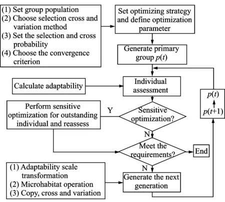
Fig.1 Flowchart of optimization procedure
2 Case Study
2.1Model
Beam-frame models and 3-D box models are often used as finite element models to design the wing structure. A beam-frame model can conveniently and directly represent the stiffness characteristics when the detailed structure information is not available, but the strength constraints can not be considered for this model. However, a 3-D model can comprehensively take multiple constraints into account, especially the strength constraints. Both the aforementioned finite element models are built, as shown in Figs.2,3. The length of wingspan is 34.0 m. The reference area of the entire wing is 120.0 m2. The sweep angle of the quarter-chord line is 25°.
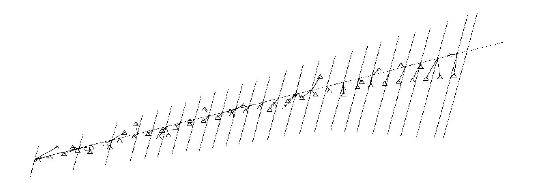
Fig.2 Beam-frame model

Fig.3 3-D model
The subsonic doublet-lattice method is used for static aeroelastic analysis and flutter analysis. The aerodynamic model is shown in Fig.4.

Fig.4 Aerodynamic model
2.2Objective function
The weighted sum of torsional and vertical bending stiffness at each station is introduced as the objective function to be minimized for the beam-frame model, and the objective function to be minimized for the 3-D model is the total structural weight.
2.3Constraints
Because the strength constraints could not be considered for the beam-frame model, only aeroelastic constraints are considered in its optimization procedure. In accordance with the design requirements, the load cases and constraints are specified as follows:

(2) Flutter speed at sea level is not less than 320 m /s. For the 3-D model, besides the above-mentioned constraints, the strength constraints should also be met, that is, the maximum stress of the upper and lower skin cannot exceed the allowable values. Meanwhile, the thickness of upper and lower skin cannot be lower than the allowable value due to the manufacturing requirements[23].
2.4Design variables
For the beam-frame model, the main beam is divided into 26 parts. The initial values of torsional and vertical bending stiffness at each position of the wing are estimated as baseline values based on a reference wing, which is a currently existing similar type[12-13]. During the optimization, torsional and vertical bending stiffness of wing at each position are respectively described as product of their baseline values and scaling coefficients. Accordingly, these 52 scaling coefficients are adopted as the design variables for the beam-frame model. The domain of these design variables are defined from 0.9 to 1.3.
The material of the two models is aviation aluminum-alloy. The upper and lower skins of the 3-D model are divided into 25 zones, respectively. The thicknesses of these 50 zones are regarded as design variables for the 3-D model.
3 Sensitivity Analysis and Optimization of Beam-Frame Model
3.1Aeroelastic response of wing with baseline stiffness
For the initial model with baseline stiffness, the twist angle at wing tip is 2.63° and the vertical displacement at wing tip is 13.8% of the half wingspan at the given load case (2.5g pull-up lift trim). The flutter speed of the wing with root fixed is 305.3 m/s at sea level. The coupling modes are the first-order bending mode and first-order torsional mode.
It is indicated that the twist angle at wing tip and the flutter speed cannot meet the constraints for the initial model.
3.2Various design variables with respect to twist angle at wing tip
For the convenience of display, the sensitivity information is given at every 10% of the half wingspan from wing root to wing tip, and the wing is artificially divided into three regions. The inner region is defined as the region between the wing root and the position at 40% of half wingspan. The outer region is defined as the region between the position at 80% of half wingspan and the tip, while the middle region is defined as the region between the positions at 40% and 80% of half wingspan.

Fig.5 Importance of various variables of beam-frame model with respect to twist angle at wing tip
The importance of various variables with respect to the twist angle at wing tip for the beam-frame model is shown in Fig.5. It is indicated that the twist angle at wing tip is mainly affected by the vertical bending stiffness in the middle region and the torsional stiffness in the outer region. It is negatively correlated with the vertical bending stiffness and positively correlated with the torsional stiffness.
Since the elastic axis of a backswept wing is located relatively backward, when an upward bending deformation is induced, the cross section with wing ribs of the wing exhibits a torsional deformation with an upward deformation of the trailing edge relative to the leading edge. Thus, reducing the vertical bending stiffness will increase the bending deformation and the twist angle at wing tip. However, since the aerodynamic center is located in front of the elastic axis, the aerodynamic moment leads to an upward deformation of the leading edge relative to the trailing edge. So reducing the torsional stiffness will decrease the twist angle at wing tip. Compared to the twist angle caused by bending deformation, the part caused directly by torsional deformation is relatively small.
For all regions of the wing, the importance of vertical bending stiffness with respect to the twist angle at wing tip does not differ that much like torsional stiffness, but the value of stiffness in middle and outer regions is much lower than the inner region. Therefore, in order to satisfy the same constraint of twist angle at wing tip, a lighter structural weight can be obtained by increasing the vertical bending stiffness of the middle and outer regions rather than that of the inner region.
3.3Various design variables with respect to vertical displacement at wing tip
The importance of various variables with respect to the vertical displacement at wing tip for the beam-frame model is shown in Fig.6, which indicates that the vertical displacement at wing tip is negatively correlated with both of the vertical bending and torsional stiffness. It is mainly affected by the vertical bending stiffness of inner and middle regions, while not so much by the torsional stiffness.

Fig.6 Importance of various variables of beam-frame model with respect to vertical displacement at wing tip
3.4Various design variables with respect to flutter constraint
Fig.7 shows the importance of various design variables with respect to the g value of the flutter traversing branch in v-g plot at 320 m/s. It can be seen from Fig.7 that the g value is positively correlated with the vertical bending stiffness and negatively correlated with the torsional stiffness. Furthermore, the torsional stiffness of the middle and outer regions has the most important influence on the g value. An efficient and economical way to improve flutter characteristics is to increase the torsional stiffness of the middle and outer regions.

Fig. 7 Importance of various variables of beam-frame model with respect to g values of flutter branch in v-g plot at 320 m/s
3.5Design for the baseline model
Aeroelastic analysis for the baseline model in Section 3.1 shows that the twist angle at wing tip and flutter speed do not satisfy the constraints. According to the conclusions drawn by Section 3.2 to 3.4, by increasing the vertical bending stiffness of the middle region or decreasing the torsional stiffness of the outer region, the twist angle at wing tip can be decreased. By increasing the torsional stiffness of the middle and outer regions, the flutter characteristics can be improved.
3.6Results
The scaling coefficients of torsional and vertical bending stiffness of the optimal solution are displayed in Fig.8. It is indicated that these scaling coefficients are almost close to the lower boundary of their domain in the inner region of the wing. At the middle region of the wing, these scaling coefficients raise to their upper boundary gradually. At the outer region, the scaling coefficients of bending stiffness are still close to the upper boundary, while the scaling coefficients of torsional stiffness decrease for the sake of reducing the twist angle at wing tip.

Fig.8 Stiffness scaling coefficients of optimal solution for beam-frame model
It can also be found that the aeroelastic characteristics of the wings are mainly affected by the stiffness of the middle and outer regions.
The optimal stiffness distribution is well consistent with the design guidance, thus proving that the sensitivity analysis and optimization procedure are correct and effective.
4 Sensitivity Analysis and Optimization Results of 3-D Model
In order to further study the influence of aeroelastic constraints on structure design of various wing parts, a 3-D box model is built to consider the strength constraints. The related research is performed by sensitivity analysis and comparison of optimization results with and without aeroelastic constraints.
4.1Various design variables with respect to twist angle at wing tip
The importance of various variables with respect to the twist angle at wing tip for the 3-D model is shown in Fig. 9. It is indicated that the twist angle at wing tip is mainly affected by the skin thickness of the middle region. The twist angle at wing tip is negatively correlated with the skin thickness of the inner and middle regions, and positively correlated with the outer region. To decrease this kind of deformation, the most efficient and economical way is to increase the skin thickness of the middle region. The trend reflected in Fig. 9 is basically consistent with that in Fig.5.

Fig.9 Importance of various variables of 3-D model with respect to twist angle at wing tip
4.2Various design variables with respect to vertical displacement at wing tip
The importance of various variables with respect to vertical displacement at wing tip for the 3-D model is shown in Fig.10, which indicates that the vertical displacement at wing tip is negatively correlated with skin thickness. It is mainly affected by the skin thickness of the inner and middle regions.
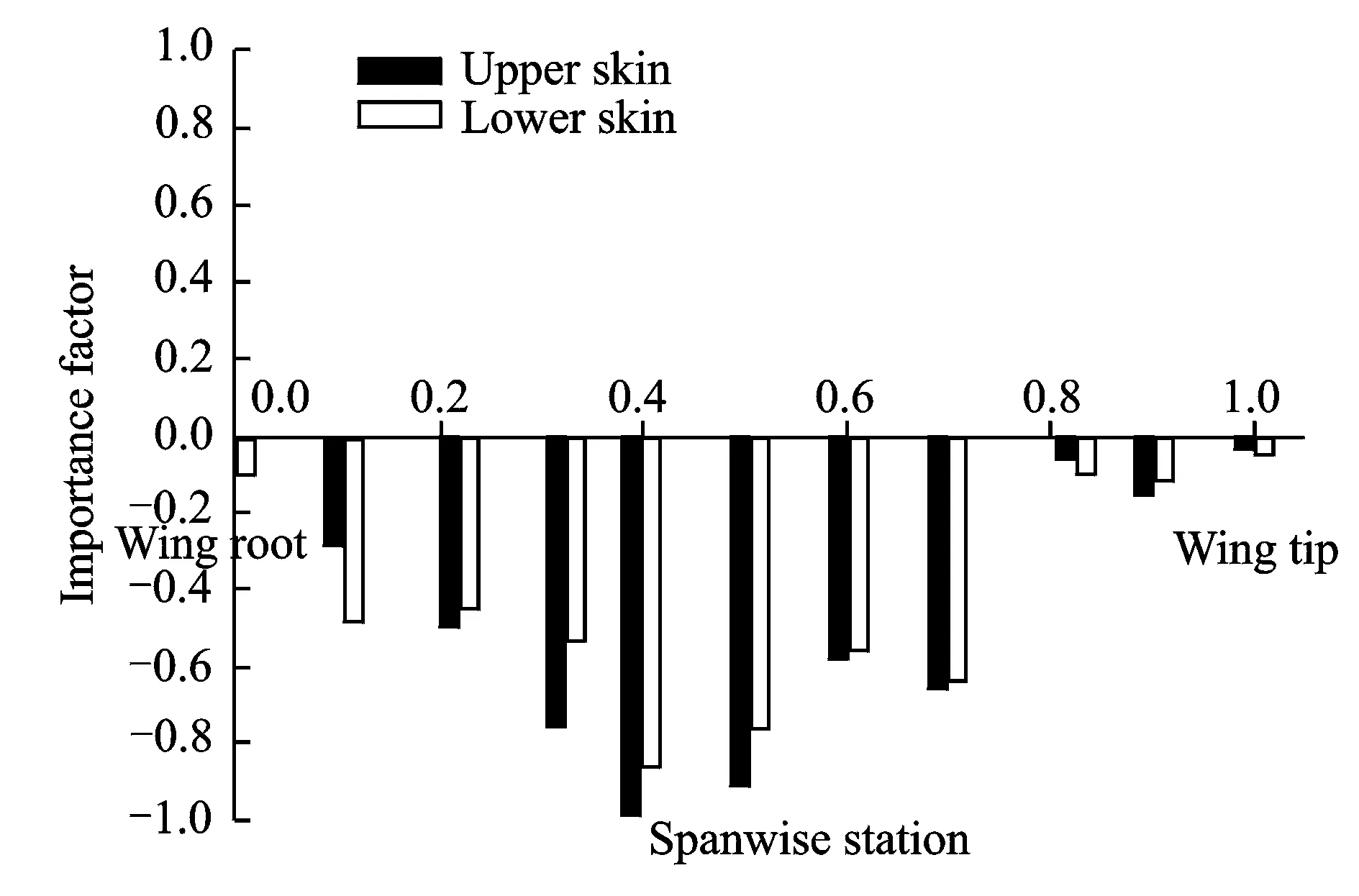
Fig.10 Importance of various variables of 3-D model with respect to vertical displacement at wing tip
4.3Various design variables with respect to flutter constraint
Fig. 11 shows the importance of various design variables with respect to the g value of flutter traversing branch in v-g plot at 320 m/s. It can be seen from Fig.11 that the g value is negatively correlated with skin thickness and mainly affected by the skin thickness of the middle region. The results are well consistent with that of the beam-frame model.
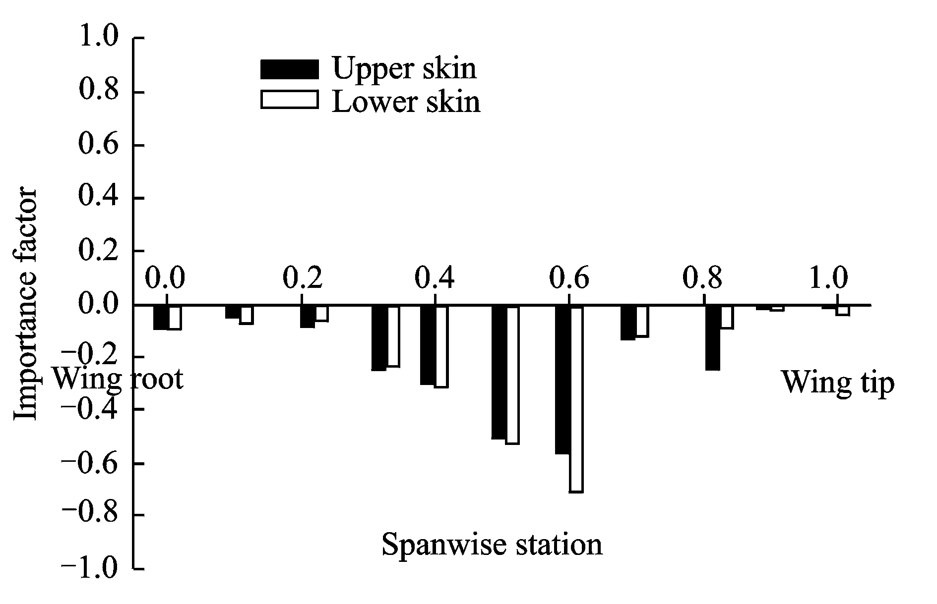
Fig.11 Importance of various variables of 3-D model with respect to g values of flutter branch in v-g plot at 320 m/s
4.4Comparison of optimization results with and without aeroelastic constraints
By using genetic/sensitivity hybrid algorithm based optimization procedure, two optimization cases are carried out. Only strength constraints is considered in the first case, while both strength and aeroelastic constraints are considered in the other one. The results of two cases are compared.
Comparison between the two results in terms of aeroelastic response is shown in Table 1. It is indicated that the design requirement of the twist angle at wing tip and the flutter speed cannot be met by just considering the strength constraints. The stiffness of middle and outer regions should be increased to meet these requirements according to the conclusions drawn by Figs.5, 7.
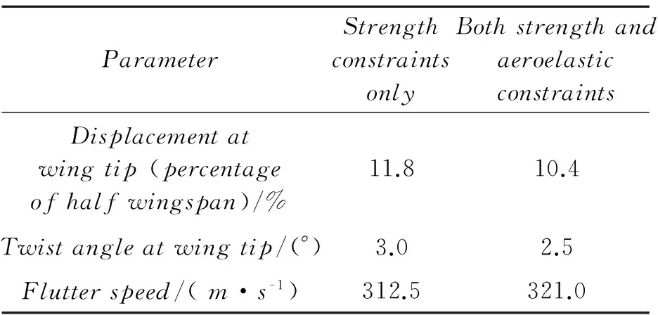
Table 1 Comparison of aeroelastic response of optimization results with different constraints
Figs.12, 13 show the comparison between the results of two cases in terms of skin thickness distribution. Compared with the one only considering the strength constraints, an obvious increase of the skin thickness in the middle region is obtained by considering aeroelastic constraints, while the difference is small in the inner and outer regions. It is illustrated that the strength constraints play a major role in determining the skin thickness of the inner region, while aeroelastic constraints have major influence on skin thickness of the middle region. In the outer region, the main restrict comes from manufacturing technology constraints. The optimal wing stiffness distribution is also well consistent with the former conclusions made by sensitivity analysis.
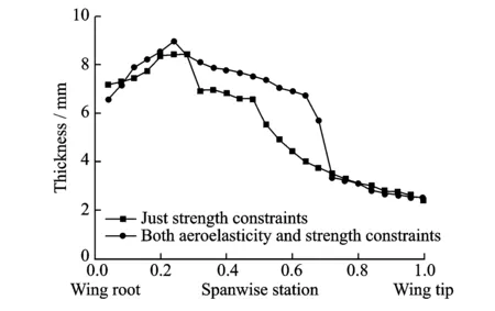
Fig.12 Comparison of thickness distribution of upper skin

Fig.13 Comparison of thickness distribution of lower skin
5 Conclusions
The relationship between stiffness distribution and aeroelastic performance for a beam-frame model and a 3-D model is investigated based on aeroelastic optimization of global stiffness design for high-aspect-ratio wings. By sensitivity analysis and optimization, the following conclusions can be drawn:
(1) The twist angle at wing tip is mainly affected by the vertical bending stiffness of the middle region and the torsional stiffness of the outer region. By increasing the vertical bending stiffness of the middle region or decreasing the torsional stiffness of the outer region, the twist angle at wing tip can be decreased. The vertical displacement at wing tip is mainly influenced by the vertical bending stiffness of the inner and middle regions of the wing. By means of increasing the vertical bending stiffness of the middle region, the vertical displacement at wing tip can be decreased without gaining too much weight. The flutter speed is mainly influenced by the torsional stiffness of the middle and outer regions, and increasing the torsional stiffness in these regions can thus increase the flutter speed.
(2) The stiffness distribution in the middle region of the wing is mainly influenced by aeroelastic constraints such as vertical displacement at wing tip, twist angle at wing tip and flutter speed. As for the structural design in the inner region of the wing, great attention should be paid to the strength constraints.
(3) Stiffness distribution design laws summarised from sensitivity analysis for high-aspect-ratio wings are in good consistency with the results from aeroelastic optimization, thus proving the design laws and the optimization procedure convincible. Either the beam-frame model or the 3-D model can be chosen to perform aeroelastic optimization based on the amount of given information, the requirement of efficiency and the type of constraints. The optimal stiffness distribution is more precise and reasonable than that of the conventional estimation method.
Acknowledgements
This work was supported by the National Natural Science Foundation of China (Nos. 11302011, 11372023, 11172025).
[1]STANFORD B, BERAN P. Minimum-mass panels under probabilistic aeroelastic flutter constraints [J]. Finite Elements in Analysis and Design, 2013(70/71):15-26.
[2]CHEN G B, YANG C, ZOU C Q. Fundamentals of aeroelasticity [M]. 2nd ed. Beijing: Beihang University Press, 2010:1-12. (in Chinese)
[3]YANG C, WU Z G, WAN Z Q, et al. Principles of elasticity of aircraft [M]. Beijing: Beihang University Press,2011:7-10. (in Chinese)
[4]HWANG J, KENWAY G, MARTINS J. Geometry and structural modeling for high-fidelity aircraft conceptual design optimization [C]∥15th AIAA/ISSMO Multidisciplinary Analysis and Optimization Conference. Atlanta: AIAA, 2014.
[5]LIU D Y, WAN Z Q, YANG C, et al. Aeroelastic optimization design of global stiffness for high aspect ratio wing [J]. Acta Aeronautica et Astronautica Sinica, 2011,32(6):1025-1031.
[6]CAVAGNA L, RICCI S, TRAVAGLINI L. Structural sizing and aeroelastic optimization in aircraft conceptual design using NeoCASS suite [C]∥ 13th AIAA/ISSMO Multidisciplinary Analysis Optimization Conference. Texas: AIAA, 2010.
[7]CAVAGNA L, RICCI S, TRAVAGLINI L. Aeroelastic analysis and optimization at conceptual design Level using NeoCASS suite [C]∥ 52nd AIAA/ASME/ASCE/AHS/ASC Structures, Structural Dynamics and Materials Conference. Colorado: AIAA, 2011.
[8]CAVAGNA L, RICCI S, RICCOBENE L. Structural sizing, aeroelastic analysis, and optimization in aircraft conceptual design [J]. Journal of Aircraft, 2011,48(6):1840-1855.
[9]MAUTE K, LESOINNE M, FARHAT C. Optimization of aeroelastic systems using coupled analytical sensitivities [C]∥ 38th Aerospace Sciences Meeting and Exhibit. Nevada: AIAA,2000.
[10]MAUTE K, LESOINNE M, FARHAT C. Analytically based sensitivity analysis and optimization of nonlinear aeroelastic systems [C]∥ 8th Symposium on Multidisciplinary Analysis and Optimization. California: AIAA, 2000.
[11]NIGAM N, AYYALASOMAYAJULA S K, QI X, et al. High-fidelity weight estimation for aircraft conceptual design optimization [C]∥ 16th AIAA/ISSMO Multidisciplinary Analysis and Optimization Conference. Texas: AIAA, 2015.
[12]HUO Y Y, TAN S G, GUO R J. Engineering considerations on aeroelastic design of large aircraft [C] ∥ 11st National Aeroelastic Seminar. Kunming: National Aeroelastic Academic Council, 2009:509-513. (in Chinese)
[13]LIU D Y, WAN Z Q, YANG C. Primary modeling and analysis of wing based on aeroelastic optimization[C] ∥ 51st AIAA/ASME/ASCE/AHS/ASC Structures, Structural Dynamics, and Materials Conference. Florida: AIAA, 2010.
[14]RODDEN W P, JOHNSON E H. MSC/Nastran aeroelastic analysis user's guide V68[M]. Los Angeles: MSC Software Corporation, 2004: 55-67.
[15]WAN Z Q, LIU D Y, TANG C H, et al. Studies on the influence of spar position on aeroelastic optimization of a large aircraft wing [J]. Science China Technological Scientces, 2012,55(1):117-124.
[16]LOUW H van Z, MOTODI S M. Unrestrained aeroelastic divergence and the p-k flutter equation [J]. Journal of Aircraft, 2001,38(3):588-590.
[17]YANG F. Study on Design Technologies of Comprehensive Optimization in Compound Materials Wing Structure [D]. Northwestern Polytechnical University, 2001. (in Chinese).
[18]LILLIEO M. Aeroelastic optimization of composite wings using the dynamic stiffness method [J]. Aeronautical Journal, 1997,101 (1002):77-86.
[19]TAYLOR J M, BUTLER B. Optimum design and validation subject to frequency constraints of flat composite beams [J]. AIAA Journal, 1997,35(4):746-748.
[20]JIANG Z, CHEN W, GERMAN B J. Statistical sensitivity analysis considering both aleatory and epistemic uncertainties in multidisciplinary design[C]∥15st AIAA/ISSMO Multidisciplinary Analysis and Optimization Conference. Georgia:AIAA,2014.
[21]WAN Z Q, YANG C. Application of design sensitivity in aeroelastic genetic optimization [J]. Journal of Beihang University, 2006,32(5):508-512. (in Chinese).
[22]WAN Z Q, YANG C. Aeroelastic optimization of a high aspect-ratio composite wing [J]. Acta Materiae Compositae Sinica, 2005,22(3):145-149. (in Chinese).
[23]General Editorial Committee of Aircraft Design Manual. Aircraft design manual volume 10: structure design [M]. Beijing: Aviation Industry Press, 2000:144-157. (in Chinese).
Dr. Wan Zhiqiang is currently a professor at School of Aeronautic Science and Engineering, Beihang University. His major research interests are aircraft design and optimization, aerothermoelasticity of hypersonic vehicles, and adaptive structures.
Mr. Du Ziliang is currently a Ph.D. candidate at School of Aeronautic Science and Engineering, Beihang University. His major research interests are aircraft design and optimization and aerothermoelasticity of hypersonic vehicles.
Mr. Wu Qiang is currently an engineer of Shanghai Aircraft Design and Research Institute.
Dr. Yang Chao is currently a professor at School of Aeronautic Science and Engineering, Beihang University. His major research interests are aeroelasticity, flight dynamics, and aircraft design.
(Executive Editor: Zhang Tong)
, E-mail address: yangchao@buaa.edu.cn.
How to cite this article: Wan Zhiqiang, Du Ziliang, Wu Qiang, et al. Stiffness distribution and aeroelastic performance optimization of high-aspect-ratio wings [J]. Trans. Nanjing Univ. Aero. Astro., 2016,33(3):243-251.http:∥dx.doi.org/10.16356/j.1005-1120.2016.03.243
V211.47Document code:AArticle ID:1005-1120(2016)03-0243-09
杂志排行

Transactions of Nanjing University of Aeronautics and Astronautics的其它文章
- Behavior of Corrosion-Repaired Concrete Beams Reinforced by Epoxy Mortar
- DNS Study on Volume Vorticity Increase inBoundary Layer Transition
- Numerical Calculations of Aerodynamic and Acoustic Characteristicsfor Scissor Tail-Rotor in Forward Flight
- Robust Fault-Tolerant Control for Longitudinal Dynamics of Aircraft with Input Saturation
- Model Updating for High Speed Aircraft in Thermal Environment Using Adaptive Weighted-Sum Methods
- Removing Random-Valued Impulse Noises by a Two-Staged Nonlinear Filtering Method