液力变矩器的减振性能分析
2015-12-17张祖金
液力变矩器的减振性能分析
Analysis of Torsional Damper in Torque Converter
张祖金1, a
采埃孚(中国)投资有限公司
aZujin.Zhang@zf.com
ZHANGZujin1, a
1ZF(China)InvestmentCo.,Ltd.
aZujin.Zhang@zf.com
[摘要]分析车辆动力总成的扭转振动特性,有助于改善车辆的舒适性和经济性。本文着重介绍自动变速箱的扭振减振性能,通过理论假设,简化典型的横置前驱得机械模型,并建立相应的数学模型。基于此数学模型,通过MATLAB计算仿真,比较评估相同扭振减振器不同参数的对系统减振特性的影响,以及介绍在不同减振器下差速器的速度响应的区别。
Abstract[]Recognizing torsional vibration of the powertrain in vehicle is the main topic with regard to the comfort, and furthermore to fuel economy. This paper is analyzing the torsional damping performance of automatic transmission, mainly simplifying the mechanical model of typical front - transversal powertrain and building up the mathematical model; at the end evaluate the system characteristics affected by different damping rates of same type damper via MATLAB calculation, in addition introduce the differential reaction of different damper types.
关键词:自动变速箱液力变矩器扭振减振器NVHMATLAB
文章编号:1006-8244(2015)03-003-10
中图分类号:U463.22+1.1
Key words: automatic transmissiontorque convertertorsional dampingNVHMATLAB
1 前言
当前市场上对于乘用车驾驶舒适性的要求显著提高,与此相反的是越来越高的发动机动力要求和不断要求降低成本的变速箱。在自动变速箱中,扭转振动引起的变速箱噪音和振动需通过集成在液力变矩器中的扭振减振器来减少甚至消除,因此需要选择合适的减振器。然而,实际应用中减振器的选择很大程度上取决于成本,并且需要匹配各种工况。所以对低扭矩的发动机、紧凑的布置空间和低成本控制的应用,此时可以选择基础的单级减振器。
本文所讨论的变速箱是应用于横置前驱的动力总成,此系统因布置空间有限也对发动机的尺寸有所限制。自动变速箱中由液力变矩器取代了手动变速箱中的离合器,但液力变矩器中也包含锁止离合器和扭振减振系统。通过液力变矩器的液力耦合实现车辆起步后,合适的扭振减振器能够实现在较低的发动机转速下闭合锁止离合器, 因此可以满足舒适性要求的同时还能降低油耗。扭振减振器的选择需要在开发前期进行筛选评估。
1 Introduction
Comfort driving requirements in the passenger car are increasing significantly every year from market, in contrast to higher excitation of engine and lower cost of transmission. Transmission noise caused by torsional vibration shall be substantially reduced or even eliminated by the torsional damper of torque converter, so the correct rate of advanced damper shall be selected. However, the selection of damper type is often dependent on the cost, and the rate needs to be balanced for all operating conditions. The standard damper system will be applied when the powertrain comes to low torque engine, compact configuration space and low cost of transmission.
本文所讨论的扭转减振器的分析主要关注于以下两个方面,第一点是通过MATLAB计算,比较评估相同扭振减振器不同参数的对系统减振特性的影响,第二点是介绍在不同减振器下差速器的速度响应的区别。因此,首先讨论装配自动变速箱的动力总成的架构,从而建立了系统的数学模型,并在最后进行上文所提到两点进行展开讨论。
2 扭振减振器的结构分类
扭振减振器的功能主要是阻断发动机的扭振激励传到自动变速箱, 因此扭振减振器在动力总成的位置应位于发动机和变速箱的输入涡轮之间。理想状态下所有的扭振激励都被消除,但实际中总有一部分扭振激励会传递到自动变速箱。这就要求扭振减振器之后传递动力到自动变速箱输入轴的零件应具有较小的转动惯量,以减小侵入自动变速箱的扭振强度。这就是需要选择合适的扭振减振结构形式的原因。与此同时,还有另外许多因素需要被考虑进去,例如动力传递的迟滞,结构布置空间等等。发展至今,扭振减振器的在液力变矩器里面结构形式种类已经能够满足各种应用的匹配要求,例如有限的轴向布置空间,最好的减振性能,低成本等需求。下图1中形象的介绍了不同的扭振减振器的结构形式:无减振(OD),单级扭振减振器(TD),涡轮扭振减振器(TTD),双级扭振减振器(TWD),以及目前最先进的离心钟摆式扭振减振器(DAT)。相较于传统的减振器, 装配了先进的扭振减振器如TWD和DAT的液力变矩器,其锁止离合器可以允许在极低的发动机转速下实现锁止并保证良好的减振性能。这一特点可以极大的降低整车的油耗,提高经济性。
单级扭振减振器是个较为传统的结构形式,常常用于紧凑型车里。下表一是同样单级扭振减振器但不同的减振参数的例子。
3 内燃机的扭振激励
考虑整个动力总成的扭振激励是非常复杂的,其激励源也是多方面的,但内燃机的扭振激励在扭振分析中是动力总成中的主要扭振激励源。如大家所知, 当某个气缸内的混合气体被压缩后再点燃,会生成一个作用于活塞顶部的燃烧膨胀气体的压力PG,此压力推动活塞下行并带动曲轴旋转,并在一个切向力TG作用下产生某个角加速度,但又马上被下一气缸的压缩冲程所阻碍,如此就导致了扭转的速度和扭矩波动。不断波动的速度和扭矩随时间变化并产生了周期性的扭振激励。本文只讨论由内燃机多缸周期性工作所产生的激励。
The transmission in this paper is designed for the front - transversal powertrain which normally requires compact design of transmission as well as limited size of engine. Automatic transmission is normally equipped with hydrodynamic torque converter, which integrates a lock-up clutch and a torsional damper system. Torsional damper with adequate rate allows the lock-up clutch close at an early stage with low engine speed after vehicle launching by hydrodynamic power transmitting, so that it will contribute to not only comfort but also fuel economy. An appropriate rate of torsional damper needs to be pre-evaluated at the beginning of design.
Analysis of torsional damper in this paper mainly focus on two aspects, first is to evaluate the system characteristics affected by different damping rates of same type damper via MATLAB calculation, second is to introduce the differential reaction of different damper types. So firstly introduce the features of the powertrain with AT, then build up the mathematical model for the system, and at the end come to the two aspects mentioned above.
2 Configurations of torsional dampers
The function of torsional damper system is to isolate the torsional vibration from engine to transmission, so the damper shall locate among engine, turbine of TC and transmission. Ideally all the torsional vibration will be eliminated, but there is always still certain vibration that will intrude into transmission. In this case, the final part of TC transmitting power to transmission shall have less inertia in order to minimize the intensity of vibration. This is the reason for choosing proper configuration of torsional damper. In the meantime, some other factor shall be taken into consideration, like hysteresis of power transmitting, limitation of space. Nowadays torsional damper configurations inside of TC have been developed to be adaptable for all kinds of application requirements, such as limited axial space, best damping performance, low cost and so on. In Fig. 1 the different configurations are illustrated: no damper (OD), torsional damper (TD), turbine torsional damper (TTD),twin damper (TWD), and the most advanced centrifugal pendulum torsional damper (DAT). Compared to conventional converters, the lock-up clutch of a torque converter equipped with the advanced torsional damper like TWD or DAT can be applied at an extremely low engine speed. This feature can significantly reduce fuel consumption.


OD

TD

TTD

TWD

DAT

表1 两种TD减振器的减振参数
由某个气缸燃烧膨胀气体驱动生成的曲轴扭矩Tc是一个关于曲轴转角的周期性函数。又由于任何周期性函数都可以近似的以傅里叶展开式来表达,因此曲轴扭矩Tc可以表示为i个正弦函数之和,如下表达式1所示。
(1)
其中,T0是个平均值,Nm;Ti是第i阶谐波扭矩的幅值,Nm;ω是曲轴的角速度,rad/s;φi是第i阶谐
A TD damper is a conventional damper which is normally used in the compact car. In Table 1 are the damping characteristics of two TD dampers as example.
3 Torsional vibration excitation of internal combustion engine
The torsional vibration excitation in whole powertrain is very complex, and the excitation sources are so multifaceted, but the excitation of the internal combustion engine is always the main torsional vibration excitation source of driveline. As well known, each time there is a booming gas pressure PGwhen the compressed gas mixture is ignited in one cylinder, then the piston will push the crankshaft to rotate by a tangential pressure TGwith an angular acceleration, but it is immediately retarded by the compression stroke in the next cyl-波扭矩的相位角,rad。
表达式1只是关于某个气缸的的扭矩的周期变化,但是对多缸的发动机,例如4缸发动机,需要考虑其各缸的工作顺序及点火间隔。其4个气缸按照某一顺序依次点火(如1-3-4-2),且各缸之间的点火间隔φ固定为180°。据此,整合各缸所产生的扭矩即为曲轴总的输出扭矩T,而此扭矩T也包含各阶i(0.5, 1, 1.5, 2, 2.5, 3…)谐波扭矩。根据点火顺序,各缸的第i阶谐波扭矩之间会有一个相位角i*φ。每阶的扭矩都是一个扭矩矢量,可以归纳并图示为下图2。

图2各阶扭矩向量
Fig.2Torque vector at different excitation order i
如图所示,把不同的阶数归类,根据相同的相位角可以分成三组,每组对应个矢量图。且由上图各矢量的对比可知,其中一组阶数(i= 2, 4, 6…)的各扭矩矢量具有相同的相位角,也就是说这些扭矩矢量在同样一个方向叠加,增强至最大。因此,4缸发动机主激励阶数为第2阶。 在此,在扭矩T的傅里叶展开式中,只考虑主要激励阶数(i=2,4,6)的谐波扭矩。此时,相位角为0,且圆频率ω为2πn/60。 据此分析结果,并代入表达式1中,发动机扭振激励T可以表示为表达式2,可应用于强迫振动分析。
T(t)=T2sin(πn/15)t+T4sin(2πn/15)t+T6sin(πn/5)t
(2)
其中,n发动机转速,r/min;t为时间,s。
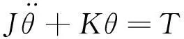
4 动力总成的扭振振动分析
为了对动力总成进行仿真分析,需要对整个系统进行质量弹性系统分析,并据此建立相应的数学模型。实际上,动力总成是个非常复杂的连续多质量弹性阻尼系统,很难用数学模型来模拟。因此,需要对系统进行一些假设以简化系统:
a. 在输入轴及输出轴之间的旋转件,假定其为集中质量,且为绝对刚性无弹性。
b. 对连接旋转件的轴,假定其为无质量,只作为弹性元件进行工作,且其刚度为线性的。
inder, resulting in speed fluctuations. Because of that, the excitation mainly comes from. In this paper, only this excitation will be taken into consideration for simulation.
The torque Tcof crankshaft generated by the explosion pressure of one cylinder is a periodic function of the crank angle. Any periodic function can be approximately expressed by Fourier expansion, so the function of Tcis a sum of numerous harmonic functions, see Eq.1 as below.
(1)
In which, T0 is average value, Nm; Ti is the amplitude of harmonic torque at i order, Nm; ω is the angular speed of crankshaft, rad/s; φi is the phase angle of harmonic torque at i order, rad.
Eq.1 can only express the torque generated by one cylinder, but there are 4 cylinders of one engine. 4 cylinders are ignited referring to defined sequence (such as 1-3-4-2) and equal ignition interval φ of 180°between every cylinder. In this case, the torques generated by each cylinder will be integrated as the result of torque of crankshaft T, and this torque T consists of different harmonic torque at every excitation order i (0.5, 1, 1.5, 2, 2.5, 3…). The harmonic torque of certain excitation order i will have a delay with the phase angle i *φ between adjacent cylinder according to ignition sequence. The torque of every order is a vector, can be illustrated as Fig.2.
It is shown from Fig.2 that there are mainly 3 kinds of vector diagram for 3 group of excitation orders, and it is also easily found that the vector of one group of excitation orders (i = 2, 4, 6…) have same phase angle, which means these torque vectors are strengthened together in same direction to maximum. So the main excitation order for 4 cylinders engine is 2ndorder. In this paper, the main excitation orders (i = 2, 4, 6) will be taken into consideration. In this case, the phase angle is 0, and ω is equal to 2πn/60. Based on the analysis and combined with Eq.1, the torsional vibration excitation of engine T can be expressed as Eq.2, which is used for forced vibration analysis.
c. 假定无阻尼,且无内部激励。
因此,此系统可认为是离散集中质量的弹性减振多自由度系统,此简化系统用于仿真模拟计算,主要关注于系统的固有特性分析等。
4.1动力总成的质量弹性系统
车辆的动力总成应进行系统的减振分析及设计,以减少甚至隔绝扭振激励。整个系统可以抽象的描述为一条扭转质量和扭转弹簧连接的动力总成链。液力变矩器中的扭振减振器也是动力总成中的一部分,因此需要将扭振减振器列在此简化的动力总成链上,以便于分析扭振减振参数对动力总成的振动解耦的作用。本文着重讨论动力总成中的变速箱,所以发动机模型会更为概括简化。另外,自动变速箱都有4至9个档位,而每个档位的转动惯量和对应的输入输出轴的刚度都可能不相同。在此这里只考虑在某个2档的情况下的动力总成。因此,基于假设和其他边界定义,结合实际的动力总成,可将系统简化为如下图3所示的结构。此系统主要包括了发动机,液力变矩器,变速箱,驱动半轴,车轮和车身其它部分。如图3所示可知,转速由发动机通过变速箱以一定速比变换后传递至驱动半轴,然后传至车轮。
T(t)=T2sin(πn/15)t+T4sin(2πn/15)t+T6sin(πn/5)t
(2)
In which, n engine speed, r/min; t is time, s.
4 Torsional vibration analysis of the powertrain
In order to analyze the powertrain system by simulation, it is necessary to build up the mathematical model based on the mass-elastic system of whole powertrain. Actually the real powertrain system is a very sophisticated continuous mass-elastic-damping system, so it is difficult to simulate by mathematical method. Here are some hypotheses in order to simplify the system:
a. Lumped mass for the rotating parts between input shaft and output shaft, which is absolute stiff without elastic
b. No mass for the shafts, which only work by elastic function. And the stiffness of elastic parts are linear
c. No damping will be considered, and no internal excitation
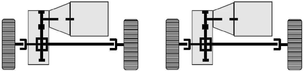
图32档时动力总成的质量弹性系统简化模型
Fig.3Mass-elastic model of powertrain in 2ndgear at drive condition
此动力总成中的所有的质量元件及弹性元件都列在下表2中。
4.2动力总成系统的数学模型
由实践经验可知,降低连接发动机和变速箱的液力变矩器的传动元件的刚度,可以有效地消除部分扭转激励进入变速箱。这就是在动力总成结构中,扭振减振器在离合器或在自动变速箱的液力变矩器中是个必不可少的元件。为了优化系统的扭转特性,需要了解动力总成系统的主振型和固有频率。各个档位都有各自的振动数学模型,这里将讨论上文所建立的2档时的动力总成系统。
基于图3所示的动力总成系统简化模型,系统的数学模型可以表达为:
Therefore, here we assume the system is a discretely distributed lumped mass - elastic - damping system with multi-degree of freedom, which is common used for the simulation of a vibration system without too much unstable factor, so that the simulation can focus on the nature behavior of the system.
4.1Mass-Elastic system of powertrain
The powertrain of a vehicle shall be systematically damped towards torsional vibration. The whole system could be abstracted and described as a chain of torsional masses and torsion springs. Torsional vibration damper in TC is a part of the pow-
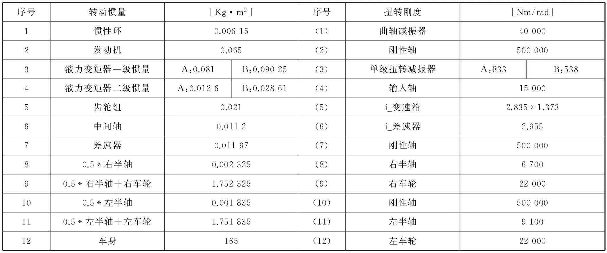
表2 2档时系统中所有质量元件的转动惯量和弹性元件的扭转刚度
(3)

为了能够对式3用MATLAB进行计算,将使用刚度矩阵法进行仿真计算。刚度矩阵法的构建方法主要定义扭转刚度Kxy为:当转动惯量y的角位移为1弧度,且其余所有的转动惯量的角位移为0时,需要作用在转动惯量x上的扭矩。基于此原则,并根据如图3所示的2档时动力总成系统简化模型,可构建系统的扭转刚度矩阵K为矩阵1。此刚度矩阵包含两个较为特别的地方,其一为扭转刚度5和6都是存在速比转换,另外一点为从差速器传递动力到左右半轴时分成左右两部分,最终得到如下矩阵。
ertrain, so it shall be considered into the system in order to understand what the decoupling function in powertrain would be with certain dynamic parameters of the torsional damper. In this paper, the analysis is mainly for the transmission, so the engine will not be considered into each cylinder. In addition, normally an automatic transmission has several gears, so the mass and elastic of each gear shall be different. Here we only consider 2ndgear situation. Therefore, the mass-elastic system of this powertrain can be simplified to the model shown in Fig. 3. The system mainly includes engine, torque converter, transmission, drive shafts, wheels and vehicle body. In Fig.3, speed transferring with certain ratio from gearsets to drive shafts, and futher to wheels.

矩阵1,系统扭转刚度矩阵K
转动惯量矩阵 J可以直接根据系统模型建立如下矩阵2:
矩阵2,系统转动惯量矩阵J
此两个矩阵中的所有转动惯量和扭转刚度都已罗列在表2中。
4.3相同类型不同减振参数下固有频率和主振型
为了研究动力总成系统的扭转振动特性,很重要的一点是要了解系统的固有频率和主振型。当系统不受外力影响,没有阻尼消减振动时,此时系统在初始激励作用下以固有频率进行自由振动。因此,系统的自由振动方程可以表示为如下式4。

(4)
这里将对配有单级减振器的系统进行计算,比较同种类型的减振器不同减振参数对系统的固有频率和主振型的影响。根据表2,在MATLAB创建扭振刚度矩阵K和转动惯量矩阵J。 由于对比相同类型不同减振参数的计算,各需要创建想应得刚度和惯量矩阵。根据创建的矩阵,按照MATLAB矩阵运算的方法,计算系统的固有频率和主振型。不同的刚度矩阵中,由表1可知,扭振减振器B相较于扭振减振器A具有较低的刚度。据经验可知,系统发生共振的风险基本上发生在第2和第3阶固有频率。因此,这里主要比较第2和第3阶固有频率下扭振振动振型。具体的对比图形见下图4。图4中,x轴式转动惯量的序号,而y轴是正则化的振型。
如图4所示,较低的扭振减振器刚度可以降低系统的固有频率并改变系统的振型。但这并不意味着扭振减振器的刚度越低越好,因为较低的扭振减振器刚度在同样的扭矩容量的情况下需要更长的减振行程,且扭振刚度越低则意味着更大的扭矩传递迟滞,最后合适扭振减振器刚度需要通过系统结合发动机周期激励进行仿真计算并通过整车及台架试验评估。
4.4 不同类型的扭振减振器的减振性能
4.4.1在发动机激励下的动力总成振动方程
运用扭转振动方程对动力总成系统进行振动仿真主要是避免动力总成系统发生共振。而在动力总成系统中发生共振的情况大概有两种:第一种是当在某一发动机转速下发动机的主激励频率与动力总成系统的某阶固有频率接近;第二种是在某阶系统的固有频率对应的振型中发动机的振幅不为0。

(a) 2阶振型比较

(b) 3阶振型比较
All the masses and elastic parts are listed in the following Table 2.
4.2Mathematical model of the system
It has been leant in the practical application that certain portion of the torsional vibration can be diminished effectively by reducing the torsional stiffness between the engine and the gearbox. This is why the torsional damper in the clutch disc or here in the torque converter is always an essential element in the powertrain. In order to optimize vibrational behavior, the vibration forms and natural frequencies of the entire powertrain have to be known. Every gear ratio results in a different vibrational model since there are strong influences on the adjacent components. The model here is going to analyze the 2ndgear.
一般而言,发动机激励的系统响应的振动方程都是随发动机转速变化的函数。但表达式2中的发动机激励函数是关于时间的函数。因此,为了更好的仿真计算,这里需要建立系统的频率响应函数,具体见表达式5到10。
首先,定义扭矩向量T和角位移向量θ为:
(5)
(6)
然后将式5和式6代入式3中,可得:
(7)
这里定义H(ω) 为:
Based on the model shown in Fig.3, the mathematical model of the system can be express as:

(3)

In order to calculate the Eq.3 by MATLAB, the stiffness matrix method will be utilized. It is defined that the torsional stiffness Kxyis: the torque applied on the inertia x when the angle of inertia y is 1 rad and the angle of all other inertias are 0. Based on the Fig.3, the torsional stiffness matrix Kcan be built as matrix 1. This matrix contains two special definitions, one is that torsional stiffness 5 and 6 are transferred with ratios, another one is that the power transferring line is divided into two lines from differential to right and left drive shafts.

Matrix 1, Stiffness matrixKof system based on the system model
(8)
由式8[1]和圆频率ω=2πn/60,可得:
(9)
最后,根据式7和式9,可得系统的频率响应函数为:

(10)
基于此频率响应函数,可以根据发动机激励计算系统的响应。
4.4.2不同类型的扭振减振器下的速度响应的例子
为了更直观的对比不同类型的扭振减振器的减振性能,这里将举例说明相同系统不同类型的扭振减振器的区别,如下图5所示的差速器速度响应的在不同类型扭振减振器下的区别。本例中将展示以下几种类型的扭振减振形式OD,TD,TTD和TWD,但没有DAT。
Inertias matrix Jcan be easily built up based on the Table 2 as matrix 2:
Matrix 2, Inertias matrix J
For the values of all stiffness and inertias can be found in the table 2.
4.3Natural frequencies and vibration forms at different damping rate

(a) 无减振时的差速器速度波动

(b) TD减振时的差速器速度波动

(c) TTD减振时的差速器速度波动

(d) TWD减振时的差速器速度波动

(e) 差速器速度波动的对比
图5清晰地显示了扭振减振器可以降低系统的固有频率,特别是可以将2阶固有频率降低到发动机非常用的转速区间,因此动力总成可以快速通过2阶固有频率的共振区间。由图可知,其中TWD减振器的减振性能最好,在系统的工作区域几乎可以消除明显的扭振影响。当然无减振的情况下是最坏的工况,很容易由于振动产生噪声甚至导致整个动力总成的损坏。
To study the torsional vibration behavior of powertrain system, it is very important to know the torsional vibration forms and natural frequencies of the entire powertrain. The natural frequency only can be calculated when the system is vibrating freely without excitation and damping. So the torsional vibration formula can be expressed as Eq.4.
(4)
5 结论
上文概述了相同类型的扭振减振器不同减振参数,以及不同类型的扭振减振器对动力总成扭转振动系统的影响。在开发阶段对动力总成系统进行扭转振动系统仿真计算分析是一个有效的系统设计方法。而在样件开发阶段,可以进一步对系统进行标定试验,根据要求调整减振参数。如此,可以根据客户需求设计合适的扭转振动性能。
参考文献
[1]吴天行,华宏星: 机械振动, 清华出版社,第60页
Here it is going to compare two TD dampers integrated into system for analysis, and these two dampers are in different TC with different damping date. Insert the matrix Kand Jinto MATLAB, and start to utilize MATLAB to calculate Eq.4 with two damper characteristics as well as corresponding inertias. Damper B is less stiff comparing to damper A as indicated in table 2. It is quite well known that high risk of resonance normally occur 2ndand 3rdnatural frequency. Here are the comparisons of the torsional vibration forms between two dampers at 2nd, 3rdnatural frequency. The details can be found in the Fig. 4. In the Fig. 4, x-axis is the number of the masses, and the y-axis is the regularized offset.
Figure 4 illustrate that the torsional damper with less stiffness will reduce the natural frequency of the system and change the torsional vibration form of the system. But this doesn’t mean that a torsional damper with lower stiffness is better, because the lower stiffness will require more angular stroke of damper with same torque capacity, and lower stiffness means bigger hysteresis, at the end the suitable rate of damper shall be verified by the system simulation with engine excitation.
4.4Damping performance of different dampers in the system
4.4.1Mathematical model of powertrain system with engine excitation
The purpose of the torsional vibration simulation is to avoid the resonance in powertrain. There are two conditions when the powertrain generate the resonance: first is that the excitation frequency of main order at certain engine working speed comes close to one natural frequency of system; second is that the torsional vibration form at this natural frequency shows the amplitude of engine is not 0.
Normally, it is necessary to see the response of the system changing as a function of the engine speed. But the excitation of engine described in the Eq.2 is as a function of time. So here it is necessary to build up the frequency-response-function for the system as shown in Eq.5-10.
First, set the torsional torque vector T and stable response angle vector θ are:
(5)
(6)
Then put Eq.5 and Eq.6 into Eq.3, so:
(7)
Here define as the matrix H(ω):
(8)
Based on Eq.8 [1] and theω was defined before as2πn/60, so:
(9)
At the end, based on the Eq.7 and Eq.9, the frequency-response-function is:

(10)
Based Eq.10, it is possible to calculate the response when the input of engine excitation is defined.
4.4.2Speed fluctuation response examples of different damper types
Here is going to introduce one example about the comparison of speed fluctuation of differential as shown in Fig.5 when different dampers are applied in the system, in order to see the damping performance of each kind of damper. The configuration types of OD, TD, TTD, TWD will be
shown in this example, but not for the DAT damper.
Figure 5 illustrate very clear that dampers can decrease the natural frequencies of system, especially move the 2ndnatural frequency to the not-normal working speed, so that the powertrain can skip very fast away resonance of 2ndnatural frequency. The best damping performance is the TWD damper, which can almost eliminate the torsional vibration out of working zone. And the worst is no damper situation, this will easily result in heavy noise or even damage in the powertrain.
5 Conclusion
It has been shown that the different respond affected by different torsional damping characteristics and different dampers’ configurations in the powertrain. Simulation calculation is an effective way for pre-evaluation of torsional damper performance in the development phase. In the prototype phase, the torsional damper can be fine-tuned after calibration. This guarantees optimum torsional damping characteristics for the OEM according customer specific requirements.
References
[1]Wu Tainxing & Hua Hongxing: Mechanical vibration, published by Qinghua university, Page 60 & Hua Hongxing: Mechanical vibration, published by Qinghua university, Page 60
