基于串行法的新型EDA优化技术的研究
2015-08-14赵建飞段新文张福祥
赵建飞+段新文+张福祥
摘 要: EDA代表了当今电子设计技巧的最新发展方向,利用EDA工具,电子设计师可以从概念、算法、协议等开端设计电子系统,大批工作可以通过计算机完成,并可以将电子产品从电路设计、性能分析到设计出IC版图或PCB版图的全部过程在计算机上主动处理完成。但EDA技术在优化方式上,却存在着一定的弱势,因此提出串行法新型优化方式,把耗用资源巨大、单时钟周期内完成的并行执行的逻辑块分割开,提取出相同的逻辑模块,在时间上复用该模块,用多个时钟完成相同的功能,从而在一定程度上解决EDA技术优化不足的问题。
关键词: 电子设计自动化; 优化技术; 串行化; 生产电路
中图分类号: TN702.2?34 文献标识码: A 文章编号: 1004?373X(2015)15?0110?02
Research on new EDA optimized technique based on serial method
ZHAO Jianfei1, DUAN Xinwen1, ZHANG Fuxiang2
(1. Department of Physics, Qinghai Normal University, Xining 810008, China; 2. Unit 93987 of PLA, Xining 810000, China)
Abstract: EDA represents the latest development trend of electronic design techniques in nowadays. By using EDA tools, electronic designers can design electronic system from concept, algorithms and protocols. A large number of work can be done by computer. The entire process of electronic products from circuit design and performance analysis to design IC layout or PCB layout can be done by computer automatically. Since EDA technique has some weakness in optimized mode, the new serial optimization method is proposed. The logic block with large resource consumption completed and executed in single clock period is segmented to extract the same logic modules. The modules are multiplexed in time. Multi?clock are applied to completing the same function, therefor the problem of EDA technique optimized insufficient can be solved to some extent.
Keywords: EDA; optimized technique; serialization; generation circuit
EDA(Electronic Design Automation,电子设计自动化)是20世纪90年代初从计算机辅助设计(CAD)、计算机辅助制造(CAM)、计算机辅助测试(CAT)和计算机辅助工程(CAE)的概念发展而来的。EDA技术就是以计算机为工具,设计者在EDA软件平台上用硬件描述语言VHDL完成设计文件,然后由计算机自动地完成逻辑编译、化简、分割、综合、优化、布局、布线和仿真,直至对于特定目标芯片的适配编译、逻辑映射和编程下载等工作。本文将会引入一种新型的串行优化方式,从而可以使通过EDA工具进行的电子设计在一定程度上占用的芯片面积更小,速度更快。
1 未优化代码分析[1]
1.1 部分代码
未优化代码如下:
entity pmultadd is
port (clk : in std_logic;
a0,a1,a2,a3: in std_logic_vector (7 downto 0) ;
b0,b1,b2,b3: in std_logic_vector (7 downto 0) ;
yout: out std_logic_vector ( 15 downto 0)) ;
end pmultadd ;
architecture a of pmultadd is
begin
process (clk ) begin
if clk′event and clk=′1′ then
yout <= a0*b0+a1*b1+a2*b2+a3*b3 ;
end if ;
end process ;
end a ;
1.2 生产电路
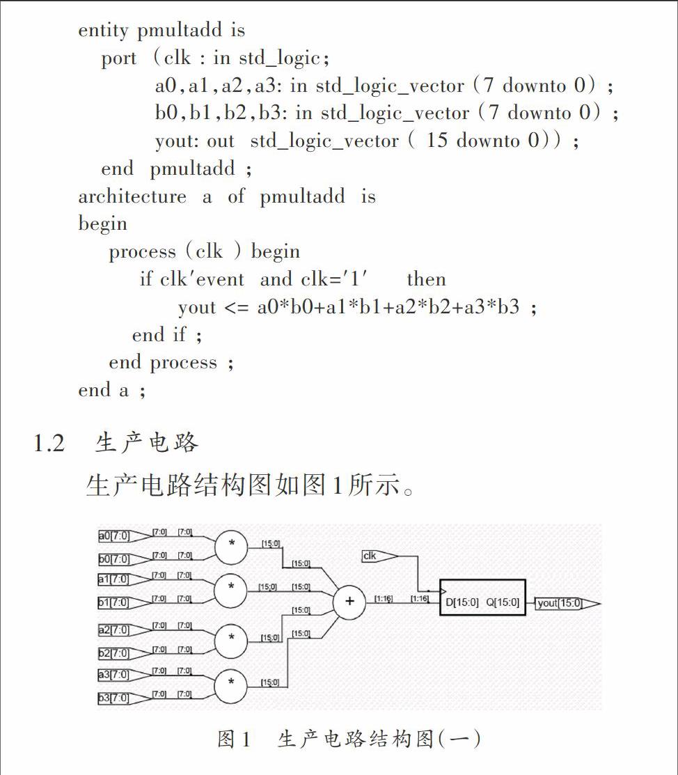
生产电路结构图如图1所示。
图1 生产电路结构图(一)
综合结果:适配至EPF10K20TC144?4使用了750个逻辑单元,资源占用率为65%。……
