Optimizing control of a two-span rotor system with magnetorheological fluid dampers
2015-04-22XINGJian邢健HELidong何立东WANGKai王锎HUANGXiujin黄秀金
XING Jian(邢健), HE Li-dong(何立东), WANG Kai(王锎), HUANG Xiu-jin(黄秀金)
(Engineering Research Center of Chemical Technology Safety, Ministry of Education, Beijing University of Chemical Technology, Beijing 100029, China)
Optimizing control of a two-span rotor system with magnetorheological fluid dampers
XING Jian(邢健), HE Li-dong(何立东), WANG Kai(王锎), HUANG Xiu-jin(黄秀金)
(Engineering Research Center of Chemical Technology Safety, Ministry of Education, Beijing University of Chemical Technology, Beijing 100029, China)
A control system aims at vibration reduction in a two-span rotor system with two shear mode magnetorheological (MRF) dampers is designed. A finite element model of the MRF damper-rotor system is built and used to analyze the rotor vibration characteristics. Based on Hooke and Jeeves algorithm and the numerical simulation analysis, an optimal appropriate controller is proposed and designed. Experimental results show that rotor vibration caused by unbalance is well controlled (first critical speed region 37%, second critical speed region 42%). To reflect advantages of optimizing strategy presented and validate the intelligent optimization control technology, detailed experiments were developed on a two-span rotor-vibration-control platform. The influence on accuracy, rapidity and stability of optimizing control for rotor vibration are analyzed. It provides a powerful technical support for the extension and application in target and control for shafting vibration.
magnetorheological fluid damper; two-span rotor; Hooke and Jeeves; optimizing control; vibration reduction
Reduction of shafting vibration is very important for safe and efficient functioning of rotating machines. The common technique for vibration control is vibration damping. Magneto rheological fluid (MRF) damper[1-3]has the advantage of rapid damping and stiffness changing in the presence of an applied magnetic field, large damping force, low-power consumption, easy to control. There are mainly two MRF dampers used in rotor vibration: magnetorheological fluid squezze film damper(MRFSFD)[4]and shear mode MRF damper[5]. Compared with MRFSFD (easy to instability, limited inhibition of critical vibration and delayed responses[6]), shear mode MRF damper achieves better vibration suppression with quicker responses.
Research literatures about shear mode MRF damper in rotor vibration reductionis mainly focus on one-span rotor system with a simple control technique called on-off method. Related studies[7-8]have shown that rotor vibration is well controlled in resonance region with on-off control technique. Furthermore, improper current may cause rotor system losing stability.
Due to the complex dynamic behavior of a rotor system, not many studies focus on the control technology for rotor vibration with shear mode MRF damper especially in multi-span rotor system. Wang J[9]developed a dynamic model for a two-disk cantilever flexible rotor supported on a MR fluid damper. Few literature till now focus on the optimizing control for the rotor vibration especially multi-span rotor using MRF damper. For this, a two-span rotor system supported by two shear mode MRF dampers was analyzed and a vibration control system was designed in this paper. An intelligent optimization control strategy for complex rotor system with high nonlinearity and uncertainty was proposed and designed to reduce vibration dynamically and effectively. It provides a powerful technical support for the extension and application in target control for shafting vibration.
1 System modeling and numerical analysis
1.1 MRF damper force model
A shear mode MRF damper was made and tested as shown in Fig.1.
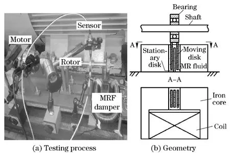
Fig.1 Testing process and geometry of the shear mode MRF damper
The MRF damper has three moving disks and two stationary disks as shown in Fig.1b. The disks are placed uniformly and alternatively with a uniform gap of 1 mm to form six relative shear surfaces. Electric current is input to the coil to generate magnetic field. The relation betweenHandτyof MRF (SG-MRF2035) in the damper is shown in Fig.2. The damper can be described by the Bingham plastic model[10]:
(1)

TherelationshipbetweendamperforceFandcurrentIisasfollows[11-13]:
Fmr(I,t)=Ssrηvmr(t)/w+Ssrτy(I)
(2)
whereFmris the damper force;Vmr(t) is the move speed of the MR damper ball bearing center;wis the width of the gap between parallel plates;Ssris the effective shear area;ηis the Newtonian viscosity.Fmrdepends onVmr(t) andτy.Nis turns per coil. The relationship betweenHandIcan be simplified:
H≈NI/w
(3)
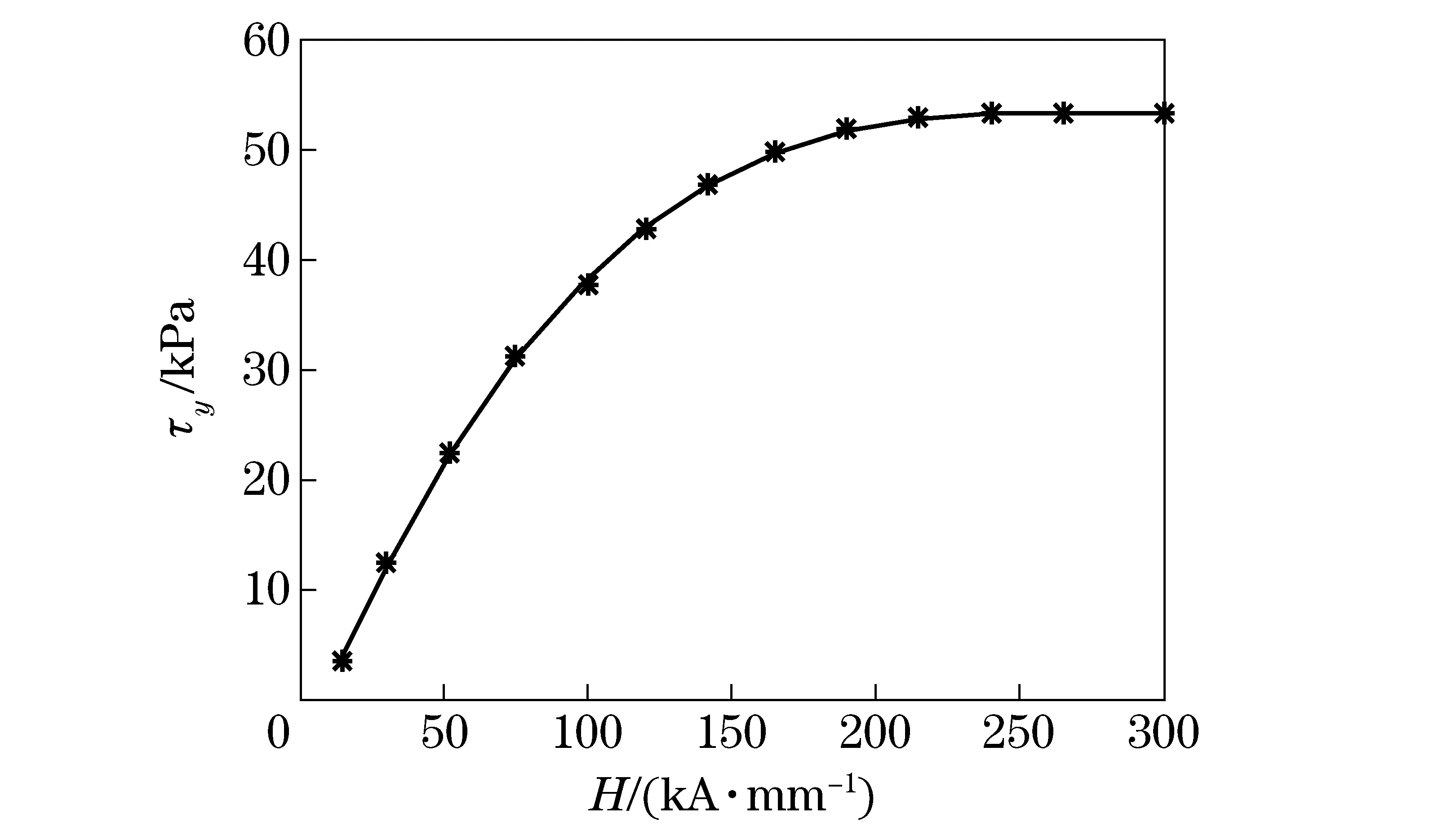
Fig.2 Relation between H and τy of MRF
1.2 System modeling and analysis
The simplified mechanical model of two-span rotor system is illustrated in Fig.3.
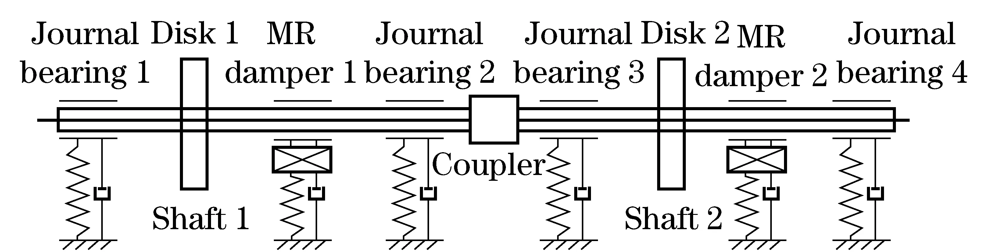
Fig.3 Simplified model of rotor-MRF damper system
According to the finite element method, the MR-rotor dynamics equation can be expressed as
(4)
whereMis the mass matrix;Cis the damping matrix;Kis the stiffness matrix;Fδ(t) is the unbalanced force; andfmr(·) is the nonlinear relationship between damping force and other coefficients (see Eq.(3),current, displacements etc.).
The basic structure parameters of the rotor system are shown in Tab.1.
The vibration modes of double shafts have been calculated through the rotor dynamics software DyRoBeS, in which MRF dampers were simplified with damping and stiffness as to simulate the shafting vibration with the MRF damper switched on current during the operation, and the simulation results as shown in Fig.4a and Fig.4b.
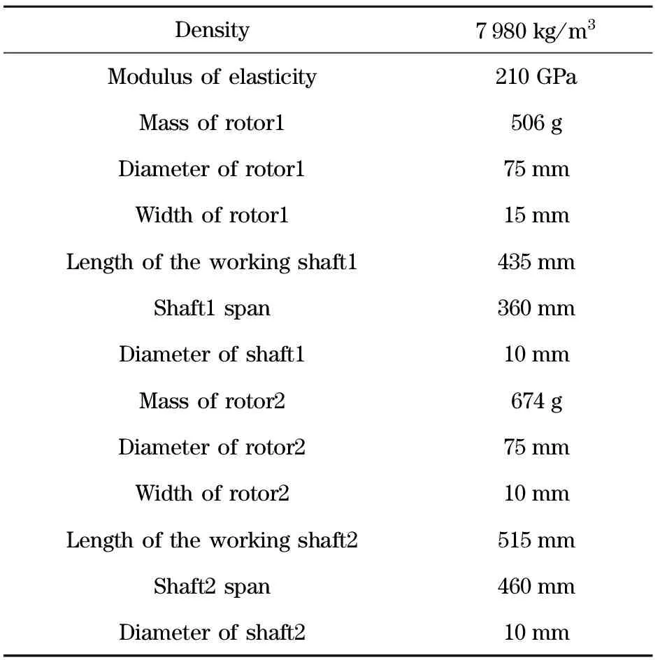
Tab.1 Basic parameters of two-span rotor system

Fig.4 Comparison of unbalanced response of two-span rotor with and without MRF dampers
The simulation results in Fig.4 indicated that the first order critical speed of the double shafts system is 2 900 r/min and the second order critical speed is 4 200 r/min without MR dampers. During the run-up process, rotor resonance occurred in shaft 2 about 2 900 r/min, which in turn raising the vibration of shaft 1 (Fig.4b). The resonance of shaft 1 occurred about 4 200 r/min. The rotor vibration is well controlled in resonance region with MRF dampers. With the increasing of the current, the damping effect is better. However, the rising current may also cause instability to the rotor system. Because MRF dampers will increase largely the support stiffness, which may cause rotor system losing stability. It is necessary to control the current properly to get better performance.
2 Optimizing controller design based on Hooke and Jeeves algorithms
Due to the complex dynamic behavior of the two-span rotor and multidiscipline interaction of MRF damper, it is hard to obtain optimal control parameter with traditional control methods based on an accurate mathematical model. Based on the modeling and numerical analysis, an optimizing control strategy to find appropriate control parameters (current) for the desired vibration amplitude is proposed and designed.
Hooke and Jeeves algorithm[14](step acceleration method or Pattern search method) was proposed in 1961,which is a family of numerical optimization methods. Pattern search methods are gradient related methods. They do not rely on the evaluation of derivatives, which is especially desirable for the cases where derivatives are either unavailable or unreliable. It is straightforward and easy to use for control parameter tuning when used in properly.
Two parameters are needed in Hooke and Jeeves algorithm, search patternPkto accelerate search process and an exploratory movesk, which varied one theoretical parameter at a time by steps of the same magnitude, and when no such increase or decrease in any one parameter further improved the fit to the experimental data, they halved the step size and repeated the process until the steps were deemed sufficiently small. The pattern Pkis a matrix as follows:
Pk=B×Ck
(6)
Ck=[ΓkLk]
(7)
where B∈Rn×nis a basis matrix fixed in every iteration, assumed normally B=I. The direction of experiment search is decided by Ck, which is a generating matrix that can vary from iteration to iteration.Γk∈Zn×rkbelongs to a finite set of matricesΓwith certain geometrical properties. Lk∈Zn×(pk-rk)contains at least a column of zeros, that means a zero step.

sk∈Δkpk≡Δk[ΓkLk]
(8)
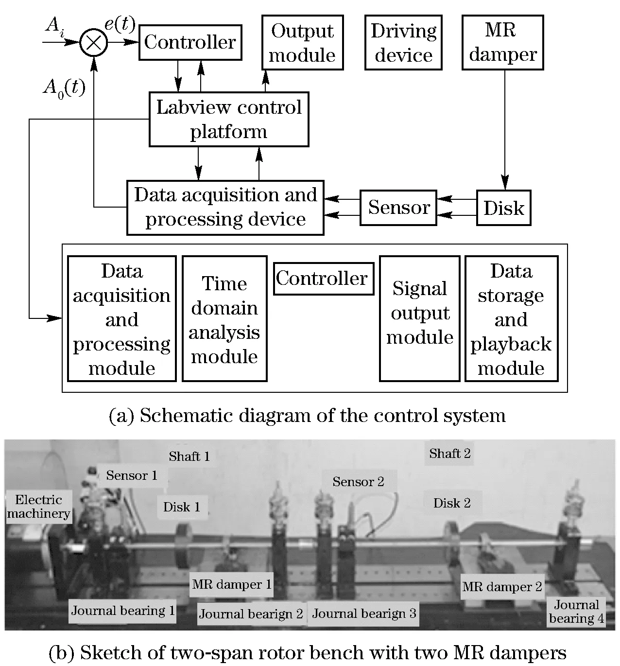
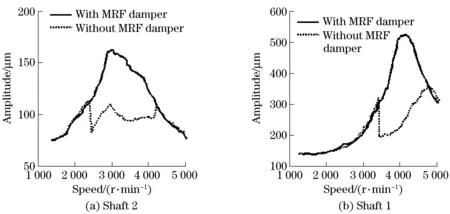
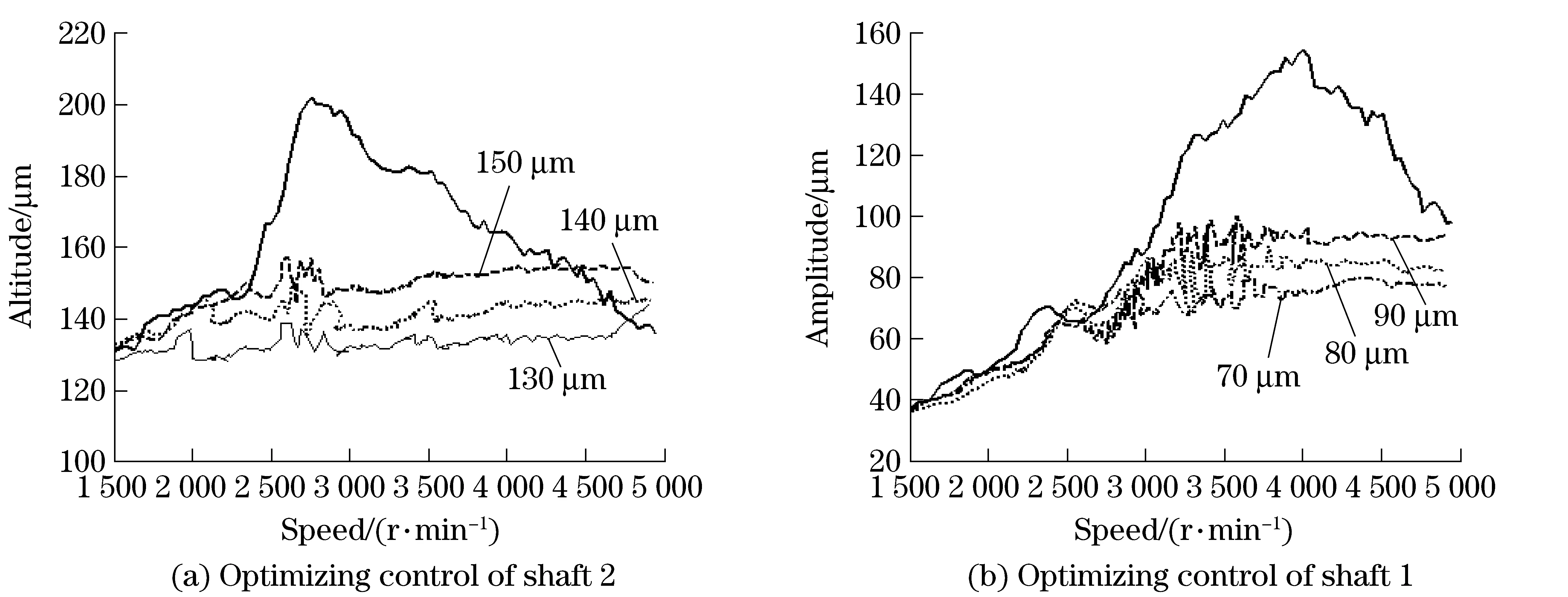
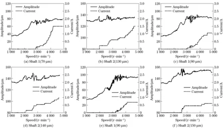
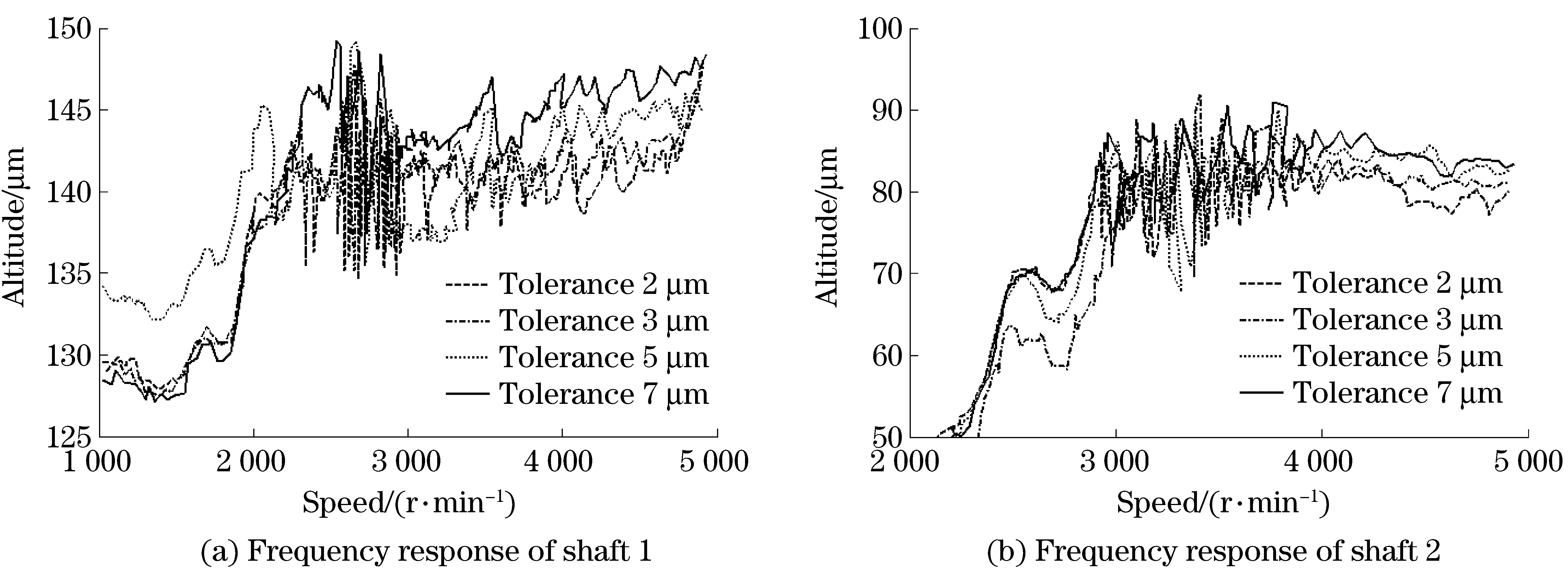
If min {f(xk+y)|y∈ΔkΓkand (xk+y)∈Ω} f(xk+sk) (9) If expressions (8) and (9) are valid,xk+1=xk+skwherexkis the current iterate.Ωis feasible region forx.Γk∈Zn×rkbelongs to a finite set of matricesΓwith certain geometrical properties. Lk∈Zn×(pk-rk)contains at least a column of zeros, which means a zero step. R,Q, and N represent the sets of real, rational, integer, and natural numbers respectively. A parallel and independent control strategy based on Hooke and Jeeves algorithm for a two-span rotor system was developed, which controlled each span non-interfering and respectively. The control scheme for optimizing controller is illustrated in Fig.5. As shown in Fig.5, the input of the designed controller is the vibration amplitudef(u) of the rotor, which was measured by a sensor. The desired valuef*for the control of rotor vibration was settled by simulations with DyroBes and experiments. The initial control currentu0∈Ωfor each rotor was chosen andΔ0>0 be settled independently. The output of the controller was the optimized currentuk. The controller is designed and accomplished in Labview platform. Fig.5 Control scheme of optimizing controller Once Pksettled to accelerate moving process andskdetermined with a linearly constrained exploratory moves algorithm,f(uk) was computed. Iff(uk+sk) The schematic diagram of the control system and the sketch of two-span rotor system with two MR dampers are shown in Fig.8. The control platform is designed and developed in Labview.The Labview control platform includes five modules,as shown in Fig.6a. The rotor system is outfitted with eddy-current type non-contact displacement sensor that measures the displacements of the flexible rotor. A real time control and data acquisition system is designed to collect the vibration data and regulate the input current to the MR damper. Experiments were done firstly to verify the simulation of rotor-MR damper system and analyze the feasibility of vibration reduction with MR damper. According to the experiments, the first order critical speed of the double shafts system is about 3 000 r/min with the maximum vibration amplitude 160 μm, and the second order critical speed is 4 800 r/min with the maximum vibration amplitude 525 μm. As showed in Fig.7, rotor vibration caused by unbalance is well controlled in two-span rotor system(first critical speed region 37%, second critical speed region 42%) with appropriate current which obtained by optimal current approximate controller. Fig.6 Schematic diagram and component of the control system To reflect advantages of optimizing control strategy and to validate the intelligent optimization control for complex rotor system with high nonlinearity and uncertainty, detailed experiments about the performance of optimizing control strategy were developed on a two-span rotor-vibration-control platform. The influence on accuracy, rapidity and stability of optimizing control for rotor vibration are analyzed through different control parameters(different desired values and different tolerances). ① Experiments with different desired values Vibration amplitudes for each shaft: shaft 1 (150 μm, 140 μm and 130 μm) and shaft 2 (90 μm, 80 μm, 70 μm): When the rotor is accelerating across two critical speeds, according to the optimizing strategy, the control current is applied. The frequency response of rotor system with MR dampers and without MR dampers are illustrated in Fig.8. Note that the experimental results in Fig.8 show the effectiveness of the control strategy. With three different desired control target values for each shaft, the control strategy is effective in the vibration suppressing. It indicated that rotor vibration caused by unbalance is well controlled both in resonance region and in non-resonance region with optimizing control strategy. It is shown in Fig.9 that the current varying with the changing vibration amplitude. The smaller the rotor vibration changes, the smoother the current curve appears. That is,the current regulating follows vibration amplitude change quickly and effectively. ②Experiments with different desired tolerances Experimental results in the rotor run-up process under the same desired vibration amplitude but with four different tolerances for each shaft were shown in Fig.10. From Fig.10, current seeking process with larger tolerance is smoother and more stable than with smaller tolerance. The smaller the tolerance is, the stricter the control requirement for optimizing process it to find an appropriate coefficient, which means the more instable curve for the current optimization. Fig.11 is the comparison of the frequency response in different tolerances. The current approximating process and the frequency response in different tolerances show the accuracy and response speed of MR dampers. The transient response with larger tolerance is more rapid but less steady than with smaller tolerance. Fig.7 Comparison of two-span rotor with and without MRF dampers Fig 8 Comparison of rotor with damper (in three desired amplitude) and without damper Fig.9 Amplitude-speed-current of two span rotor with optimizing control in different desired value Fig.10 Vibration response and current approximating process in different tolerances Fig.11 Frequency response with different tolerances ①Experiment results show that rotor vibration caused by unbalance is well controlled in two-span rotor system(first critical speed region 37%, second critical speed region 42%). ②This optimizing controller for current is regulated independently for each shaft, which is especially meaningful in a multi-span rotor system. It can be extended to a multi-span (more than three or four span) rotor system and provides a powerful technical support for the extension and application in target and control for shafting vibration. ③The stability and rapidity of transient response and efficiency of optimal approximate technique for rotor system depends on coefficients, such as tolerance, target value etc. The rapidity of optimizing control is better with longer current search step, but longer search step may affect the accuracy and stability of optimizing control. It is necessary to balance these control performance requirements (accuracy, rapidity and stability). In the premise of vibration control stability, rapidity and accuracy of control are maximized. A fixed search step is used in this paper. Further research on search step varying with different vibration amplitudes can be done to improve the efficiency, smoothness and rapidity of transient vibration response. [1] Yang G, Spencer B F, Carlson J D, et al. Large scale MR fluid dampers: modeling and dynamic performance consider-ations[J]. Engineering Structures,2002. [2] Carlson J D, Catanzarite D M, Clair K A. Commercial magnetorheological fluid devices[J].International Journal of Modern Physics B, 1996,10:2857-2865. [3] Andrzej Milecki. Investigation and control of magnetor- heological fluid dampers[J]. International Journal of Machine Tools & Manufacture,2001,41:379-391. [4] Masoud Hemmatian, Abdolreza Ohadi. Sliding mode control of flexible rotor based on estimated model of magnetorheological squeeze flim damper[J].Journal of Vibration and Acoustics,2013,135(5):1-11. [5] Wang J, Meng G. Experimental study on stability of an MR fluid damper-rotor journal bearing system[J].Journal of Sound and Vibration,2003, 262:999-1007. [6] Zhu Changsheng. Experiment investigation into the dynamic behaviors of a flexible rotor on magnetorheological fluid squeeze film dampers[J]. Journal of Functional Materials, 2006,5(37):750-753. [7] Wang J X, Meng G. Experimental study on rotor system vibration control of a squeeze MR fluid damper[J]. Journal of Aerospace Power, 2005,20(3):424-428. [8] Wang J, Meng G. Experimental study on stability of a rotor supported on a MR fluid damper and sliding bearing[J]. Journal of Vibration Engineering, 2003, 16(1):71-74. [9] Wang J, Meng G. Dynamic model of flexible rotors supported on an MR fluid damper (Ⅱ) : Cantilever rotor with two disks[J]. Journal of Foshan University:Natural Science Edition, 2003,21(1):15-18. [10] Stanway R, Sposton J L, Stevens N G. Non-linear modeling of an electrorheological vibration damper[J]. J Electrostatics, 1987,20:167-184. [11] Yang G.Large-scale magnetorheological fluid damper for vibration mitigation:modeling,esting and control[D].Indiana,USA: University of Notre Dame, 2001. [12] Winslow W M. Method and means for translating electrical impulses into mechanical forces,U.S.Patent 2417850[P]. 1947-03-25. [13] Shtarkman E M. Fluid response to magnetic field,U.S. Patent 4992190[P].1991-02-12. [14] Hooke R, Jeeves T A. Direct search solution of numerical and statistical problems[J]. J Assoc Comput Mach, 1961, 8(2): 212-229. (Edited by Wang Yuxia) 10.15918/j.jbit1004-0579.201524.0420 TP 273.1 Document code: A Article ID: 1004- 0579(2015)04- 0558- 08 Received 2014- 01- 20 Supported by the National Program on Key Basic Research Project (973 Program)(2012CB026000); Ph.D Programs Foundation of Ministry of Education of China(20110010110009) E-mail: he63@263.net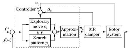
3 System design and experimental result analysis

4 Conclusions
杂志排行

Journal of Beijing Institute of Technology的其它文章
- Influence of shear sensitivities of steel projectiles on their ballistic performances
- Triaxial high-g accelerometer of microelectro mechanical systems
- Dynamic modeling and simulation for the rigid flexible coupling system with a non-tip mass
- Multi-constrained model predictive control for autonomous ground vehicle trajectory tracking
- Estimating the clutch transmitting torque during HEV mode-switch based on the Kalman filter
- Optimal tracking control for automatic transmission shift process