Novel Fault Detection Optimization Algorithm for Single Event Effect System Based on Multi-information Entropy Fusion
2014-08-12GAOXiangZHOUGuochang周国昌LAIXiaoling赖晓玲ZHANGGuoxia张国霞ZHUQiJUTing
GAO Xiang(高 翔), ZHOU Guo-chang(周国昌), LAI Xiao-ling(赖晓玲), ZHANG Guo-xia(张国霞), ZHU Qi(朱 启), JU Ting(巨 艇)
China Academy of Space Technology, Xi’an 710100, China
Novel Fault Detection Optimization Algorithm for Single Event Effect System Based on Multi-information Entropy Fusion
GAO Xiang(高 翔)*, ZHOU Guo-chang(周国昌), LAI Xiao-ling(赖晓玲), ZHANG Guo-xia(张国霞), ZHU Qi(朱 启), JU Ting(巨 艇)
ChinaAcademyofSpaceTechnology,Xi’an710100,China
Fault detection caused by single event effect (SEE) in system was studied, and an improved fault detection algorithm by fusing multi-information entropy for detecting soft error was proposed based on multi-objective detection approach and classification management method. In the improved fault detection algorithm, the analysis model of posteriori information with corresponding multi-fault alternative detection points was formulated through correlation information matrix, and the maximum incremental information entropy was chosen as the classification principle for the optimal detection points. A system design example was given to prove the rationality and feasibility of this algorithm. This fault detection algorithm can achieve the purpose of fault detection and resource configuration with high efficiency.
faultdetection;multi-informationentropy;posterioriinformationentropy;correlationinformationmatrix;singleeventeffect(SEE)
Introduction
As Very Large Scale Integration (VLSI) used widely in aerospace, the studies of soft error detection in circuit system by single event effect (SEE) attract more attention. However, any design will be confronted with the optimization problem of detection points about soft error for testability firstly. Hence, the better optimization for detection points can improve the fault detection efficiency and save the system resources.
At present, research on the optimization of detection points are focused on ICs and board-level circuits. References [1-2] make use of fault dictionary method and determinant decision diagram method to research on testable measurement and optimization of the logic faults in circuits respectively. References [3-4] set the optimization design criteria of detection points based on the fault diagnosis tree of graph theory and information theory. However, the design rationality or the criteria does not fully meet the needs of practical application with multiple faults.
Therefore, an optimal fusion algorithm of multi-information entropy for detecting faults occurred in multi-function modules is proposed based on the multi-objective detection approach and classification management methods in Ref. [5]. The algorithm derives the posteriori information from multi-fault alternative modules, and chooses the maximum information gain as the classification principle for the optimal detection points through the correlation information matrix. The analysis is as follows.
1 The Principles of Fault Detection Optimization Algorithm
1.1 Correlation information matrix
The basic idea is that the system is divided into a number of function modules according to the outputs and the inputs, expressed asA={a1,a2, …,am}. Then the moduleaiand the adjacent moduleaj{i≠j∈1, 2, …,m} establish correlation matrixRtogether, as well as the first-order correlation matrixFof detection pointTPi. At the same time, making use of the relationships betweenaiandR, the algorithm searches all the modules and builds a collection of detection points {TP1,TP2, …,TPn} ofFand indirect higher-order correlation matrixHofAbased on signal transmission. Correlation information matrix is obtained by the relationships of correlation matrix.
Figure 1 describes the calculation process of the correlation information matrix. Figure 1(a) presents the topological structure of signal transmission made up function modules, whereFiis defined as fault state of corresponding moduleai, andTPiis expressed as thePi-th detection point inserted into the path of signal transmission. The values offandhdescribed in Fig.1 (b) are detected fault states ofFandHrespectively and the correlation matrix is established. Thus, The conversion of the correlation information matrix is shown in Fig.1 (b).

(a) Topological structure of signal transmission among the function modules

(b) Correlation matrixRof function modules →correlation matrixHbetween detection points and function modules→ correlation information matrix
Fig.1 Conversion of correlation information matrix
1.2 Fusion of multi-information entropy
To facilitate correlation information matrix for optimizing fault detection point, the definition of information entropy is introduced according to Ref. [6].


log2p(Fl|TPj,ti),
(1)
which can be used to infer the posterior information entropy of multi-fault states, and evaluate the amount of the system information based on the granularity of information partition.
1.3 Optimization principles of detection points based on the information gain
The priori information entropy of fault states is expressed as Eq. (2), so the information gain of detection point can be obtained through Eq. (1) subtracted by Eq. (2), namely shown in Eq.(3).
(2)

(3)
Usually, the larger information gain becomes, the more amount of information detection points provide. So information gain will be selected as the optimization principles of detection points.
2 Optimization Algorithm of Detection Points Based on Fusion of Multi-information Entropy
2.1 Model of optimization algorithm
Assume that the decision of fault stateFlforl-th function module possesses normal state or non-normal state, and the module measurementtifor fault is always detected correctly. At the same time, the measurement valuetiof each detection point is discrete and independent, and the priori probabilityp(Fl|al) of fault state with the detected module is known as the relative probability of fault occurred by SEE in the space environment.


(4)

(5)
(6)
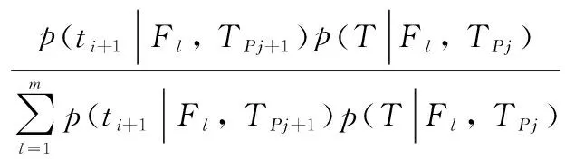
Thus the expectation of posteriori information entropy with the new added point is deduced as:

(7)
According to Eqs. (2)-(7), the information gain of the new added detection point is denoted as:
log2p(Fl|T′,TPj+1)].
(8)

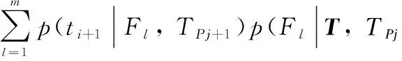
(9)
(10)
wherem0+m1=m=k. According to Eqs. (8)-(10), the information gain can be simplified as:
(11)
2.2 Optimal configuration of detection points
The detection optimization algorithm will traverseTPand evaluate maximum posteriori information gains of alternative detection points based on the correlation information matrix. Hence, the algorithm will make use of new information obtained added detection point to reduce the scope of fault occurred until the amount of information becomes zero. The main steps are as follows.
Step 1: calculate the information gain of alternative detection points based on the initial information matrix and select a detection point with the maximum information gain as the initial point.
Step 2: divide the detected vector of the information matrix into two fault state sub-information matrices according to the fault states properties of current detection points.
Step 3: delete the current detection point fromTP. Then the posterior information entropy of fault state is calculated by Eq. (7) and summed through searching each detection point ofTP.
Step 4: select a detection point with the maximum information gain as the optimal point on the calculation of information gain for each detection point by Eq. (11).
Step 5: repeat Steps 2-4 and continue to searchTP. The algorithm will stop searching until the correlation information matrix of fault states is divided into one-dimensional matrix.
3 Simulation Results
The payloads system described in Ref. [7] will be selected as the example to prove the application of this algorithm feasible. The state flow diagram of detected signals is constructed in Fig.2, whereTP1-TP8are alternative detection points andF1-F7are the fault state set associated with the function modulesa1-a7. The correlation information matrix and the maximum posteriori information gainsI(F|T′,TPj+1) are shown in Table 1 through this algorithm.

Fig.2 State flow diagram of detected signals
As seen from Table 1, the vectors betweenTP2versusTP5, andTP6versusTP7are the same respectively in the correlation information matrix. SoTP2versusTP5andTP6versusTP7will be alternative randomly respectively. The prior probability of fault state of each module is obtained based on the definition of the rough entropy in Ref. [8]. While the posterior probabilities of the fault states will be calculated by the relevant Eq. (9). Then the detection point with the maximum posteriori information gain calculated by Eq. (10) will be chosen as the optimal detection point.

Table 1 Correlation information matrix and maximum posteriori information gain of modules
The results in Table 1 show that the maximum posteriori information gainsI(F|T′,TP j+1)1ofTP3,TP4, andTP6are the same. Considering the output of the detection pointsTP4is easy to measure and is chosen as the first optimal detection point. At this time, the correlation information matrix will be divided into two sub-matrices where the values ofI(F|T′,TP j+1)2with the detection points exceptTP4are calculated, andTP6is selected as the second optimal detection point. In the same way, the third and fourth optimal detection pointsTP3andTP8are obtained respectively. Therefore, the decision of optimal detection points should beTP4,TP6,TP3, andTP8.

Fig.3 Fault diagnosis trees of soft error
According to the optimal detection points, fault diagnosis trees are drawn in Fig.3(the normality is “0” and the fault is “1”). Becausea5anda6constitute a feedback structure together which brings the loop of malfunction state inputs and the impact of fault analysis, the chosen of inserted detection points consider the combination ofF5andF6in Fig.3. And Table 2 shows the checklist of system faults based on the optimal fault detection points associated with Fig.3 so that the faults of function modules can be quickly located.
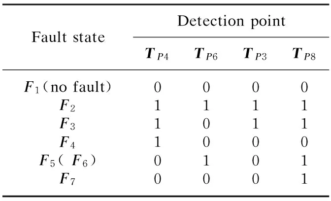
Table 2 Checklist of system faults
4 Conclusions
The algorithm based on fusion of information entropy proposed in this paper considers the influence of faults occurred in the function modules and makes use of the maximum posteriori information gains to optimize and search detection points. In this way, the system will be set to fewer detection points and lower detection steps to achieve the aim at optimization. An example of circuit system is given and used to verify this algorithm reasonable and feasible.
[1] Prasad V C, Babu N C S. Selection of Test Nodes for Analog Fault Diagnosis in Dictionary Approach [J].IEEETransactionsonInstrumentationandMeasurement, 2000, 49(6): 1289-1297.
[2] Sun X B, Chen G Y, Xie Y L. Test Point Selection for Analog Integrated Circuit [J].JournalofElectronics&InformationTechnology, 2004, 26(4): 645-650.
[3] Huang J L, Cheng K T. Test Point Selection for Analog Fault Diagnosis of Unpowered Circuit Boards[J].IEEETransactiononCircuitsandSystemsII:AnalogandDigitalSignalProcessing, 2000, 47(10): 977-987.
[4] Huang Y F, Jing B, Xia Y. Optimal Strategy of Test Point Selection for Circuit Based on Information Entropy [J].ApplicationResearchofComputers, 2010, 27(11): 4149-4151.
[5] Liu X S, Shen S L, Pan Q,etal. An Algorithm of Sensor Management Based on Information Entropy [J].ActaElectronicaSinica, 2000, 28(9): 39-41.
[6] Wang G H, He Y, Yang Z. Adaptive Sensor Management in Multisensor Data Fusion System[J].ChineseJournalofElectronics, 1999, 2(8): 136-139.
[7] Ma C S, Wang Y W, Shi H S,etal. Study on BIT Optimization Design of Airborne Electronic Equipment [J].SystemsEngineeringandElectronics, 2009, 31(9): 2276-2279.
[8] Wang Y K, Wang X Q, Xiao M Q. Research of Test Node Selecting for Fault Diagnosis Based on Value Measure [J].SystemsEngineeringandElectronics, 2009, 28(10): 1606-1608.
1672-5220(2014)06-0879-03
Received date: 2014-08-08
*Correspondence should be addressed to GAO Xiang, E-mail:cowboy-gx@163.com
CLC number:TP391 Document code: A
杂志排行

Journal of Donghua University(English Edition)的其它文章
- Optimization of Quality Consistency Problem of Electromechanical Component due to Manufacturing Uncertainties with a Novel Tolerance Design Method
- Effect of Starch Dodecenylsuccinylation on the Adhesion and Film Properties of Dodecenylsuccinylated Starch for Polyester Warp Sizing
- Interval Fault Tree Analysis of Excavator Variable-Frequency Speed Control System
- Combinatorial Optimization Based Analog Circuit Fault Diagnosis with Back Propagation Neural Network
- Reliability Allocation of Large Mining Excavator Electrical System Based on the Entropy Method with Failure and Maintenance Data
- Deployment Reliability Test and Assessment for Landing Gear of Chang’E-3 Probe