Experimental Investigation on Flow and Heat Transfer of Jet Impingement inside a Semi-Confined Smooth Channel*
2014-04-24ZhangJingzhou张靖周LiuBo刘波XuHuasheng徐华胜
Zhang Jingzhou(张靖周),Liu Bo(刘波),Xu Huasheng(徐华胜)
1.Jiangsu Province Key Laboratory of Aerospace Power System,Nanjing University of Aeronautics and Astronautics,Nanjing,210016,P.R.China;2.College of Energy and Power Engineering,Nanjing University of Aeronautics and Astronautics,Nanjing,210016,P.R.China;3.China Gas Turbine Establishment,Aviation Industry Corporation of China,Chengdu,610500,P.R.China
1 Introduction
As a matter of fact,the inlet and exit temperature levels and pressure are progressively getting higher in modern gas-turbine combustors while the percentage of compressed air available for cooling purpose becomes more limited.Undoubtedly,the decrease of the quantity of cooling air available and the increase of the gas temperature in the combustion chamber are contradictory elements of the problem,which presents a great challenge for engineers to design an efficient costeffective cooling system to meet combustor durability requirement.
Jet impingement is one of the most efficient solutions for the effective cooling of the combustor in gas turbine engines[1,2].The heat and mass transfer produced by the turbulent impinging jets have been characterized in a number of investiga-tions reviewed by Viskanta[3],Weigand and Spring[4].Basic investigations on single impinging jet with and without cross-flow were conducted for example by Goldstein and Behbahani[5],Lee et al[6],and Colucci and Viskanta[7].These investigations have shown that the heat transfer produced by an impinging jet depends mainly on a number of parameters,including the Reynolds number of the jet,the nozzle-to-plate spacing,the presence of a confining wall,and the Prandtl number,etc.Convective heat transfer enhancement,increase in the heat transfer rate uniformity,improvement in the coverage of the impingement surface,and decrease in the coolant mass flow rate are some of the concerns of jet impingement[8-14].
With regards to the effects of a confining wall on the jet impingement,Garimella and Rice[15]as well as Fitzerald and Garimella[16]performed experiments to examine the flow field of a confined jet impingement.A toroidal recirculation-flow pattern in the downstream was clearly shown.Angibletti et al[17]investigated the flow field and heat transfer for a jet impinging on a flat plate.Zhang et al[18]and Wang et al[19]studied the effect of crossflow on jet impingement heat transfer for inline and staggered arrays.Parida et al[20]made an experimental and numerical investigation on the confined oblique impingement configurations for high heat flux applications.It was observed that for the inclined impingement case,the flow had to turn and adjust to the cylindrical jet before starting to develop inside the jet holes.This caused the formation of two nonsymmetrical secondary flow regions.Especially due to this large secondary flow region,the jets got accelerated and flowed out at relatively higher velocity causing the heat transfer rates to increase locally.Moreover,the swirl generated after impingement sustained itself for a longer distance,thereby increasing the overall heat transfer rates.Some researchers addressed the effects of nozzle geometry on heat transfer and fluid flow.
Although a considerable amount of investigations have been conducted on the jet impingement heat transfer so that the design of impingement cooling systems could be optimized to produce the most effective cooling with a minimum amount of coolant,little work has been made on the heat transfer characteristics of jet impingement inside a semi-confined channel where the coolant air is constrained to evacuate in a single preferential direction toward the trailing exit.This situation could be viewed as a simplified model of impingement-convection heat transfer encountered in the combustor liner cooling configurations.The motivation of present study is to explore the effects of the impingement Reynolds number,impingement distance and the hole pitch on the flow and heat transfer characteristics inside the semi-confined channel.
2 Experimental Procedures
2.1 Experimental setup
The experimental setup is sketched in Fig.1(a).It basically consists of a test section connected to a coolant air supply passage.The coolant air from the compressor is firstly drawn through a standard flow meter and forced to enter into the plenum chamber.Then the coolant air is discharged through the orifice plate to impinge at the target plate.After impingement on the target plate,the spent air is constrained inside the semichannel to exit in only one direction(the positive x-direction as seen in Fig.1(b)).
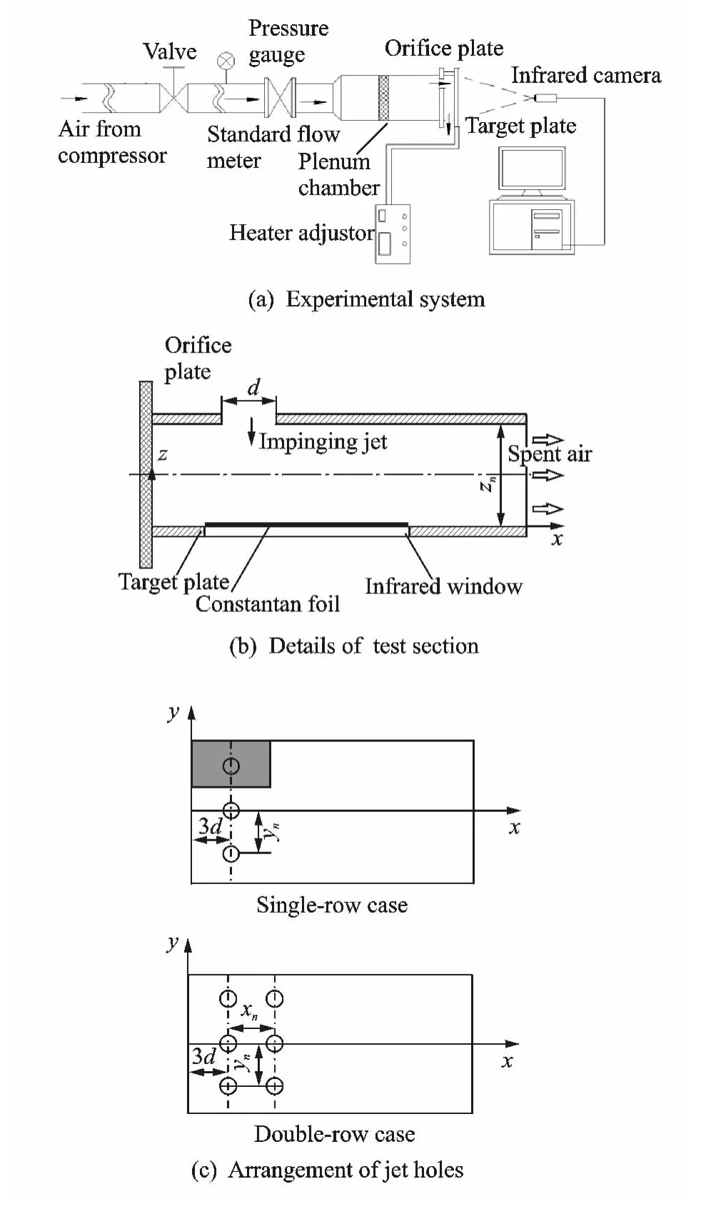
Fig.1 Schematic diagram of experimental setup
The orifice plate is made of epoxy resin of 5mm thickness.The spanwise width(y-direction)is 100mm and the streamwise length(x-di-rection)is 200mm.Single-row and double-row of circular sharp-edged holes are used to generate the impinging jets.The diameter(d)of each hole is equal to 2mm,as shown in Fig.1(c).Singlerow of impinging jets is positioned 3dfrom the closed side of the test section.The spanwise pitch(yn)between adjacent holes varies from 3dto 5d.With regard to the double-row configuration,the first row of jets is positioned 3ddownstream from the closed side of the test section.Two rows of jets are arranged inline with streamwise pitch(xn)of 3d,4dor 5d,respectively.
The impingement target is a thin constantan foil of 0.01mm thickness(70mm long,100mm wide)which is mounted on the inner surface of a nylon plate(200mm long,100mm wide and 20mm thick).The foil spans the width of the plate and is tightened up by the adjustable copper bars to tension the foil after it is heated.The impingement distance or the nozzle-to-plate spacing between the orifice plate and the target plate is adjusted by a spacer thickness,giving some different non-dimensional orifice-to-target space ratios(zn/d,impingement distance to the diameter of jet hole).The foil is heated by DC current with two-side edges connecting to the copper bars to ensure uniform heat flux.The voltage(V)and the current(I)are recorded to determine the heat flux.In the experiment,the constant heat-flux on the heating foil surface is set as 5 000W/m2.To make the object thermal image be detected by the infrared camera,a viewing window with 30mm wide and 70mm long is opened in the nylon insulation plate.
2.2 Measurement and parameter definition
The impingement Reynolds number is determined as
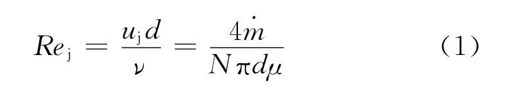
where dis the inlet diameter of jet hole,νthe kinematic viscosity of the jet,ujthe mean jet velocity at the inlet,˙mthe total mass flow rate of the air emerging from the orifice plate,μis the dynamic viscosity of the jet,and Nis the number of holes in the orifice plate.
The temperature distribution on the rear face of the foil(the opposite side of jet impingement)is measured by an infrared camera(TVS-2000 MK)working in the 3—5μm band at speed of 30 frames per second.The field of view is 25°×18.8°/0.4m,the instantaneous field of view is 1.3mrad,and the thermal sensitivity is 0.07°C at 30°C.The infrared camera calibration is conducted by using a series of thermocouples placed on the black painted test surface to act as the benchmark[21,22].These thermocouples are used to estimate the emissivity of the test surface.The emissivity of the black painted surface when viewed directly is about 0.96.Three copper-constantan thermocouples are fixed on the foil to check the heater temperature and to help determine steadystate conditions.Once the temperature field on the impinging target reaches steady,the thermal image is recorded by the infrared camera.The detective distance is set as 100mm and accordingly the transmissivity for the infrared camera is approximately regarded as 1.
In the present case,the infrared camera is used in conjunction with the″heated thin foil″steady state heat transfer sensor(Carlomagno and Cardone[23]).Since the impingement target thickness is very thin,the Biot number(Bi=hδ/λs,where his the convective heat transfer coefficient on the target surface,δandλsare the thickness and thermal conductivity of the thin target plate,respectively)is small with respect to unity,the temperature on the face of the foil opposite to the jet impingement may be considered practically the same as that on the target surface directly impinged by the jets.Considering the energy balance of a thin plate in steady state conditions,the local convective heat transfer coefficient on the target surface is evaluated as

where Twis the target wall temperature,Tjthe impinging jet temperature(metered in the plenum chamber),qjthe Joule heat flux,and qradationthe radiation heat flux,and qconvectionthe natural convection heat flux on the rear foil surface.
Due to the thermal inertia of the foil and the time averaging process of the image,present measurements have to be considered as time averaged.This means that temperature fluctuations due to flow turbulence are not measured.
The net rate of radiation heat flux is estimated as

where Tais the surrounding ambient temperature,εbackthe emissivity of nylon plate,andσthe Stefan-Boltzmann constant.
The heat loss from the back of foil by natural convection mode is determined according to the empirical relation for natural convection from vertical flat plate.

where hfis the natural convection heat transfer coefficient over the back of heated foil,which is determined according to the empirical relation for natural convection from vertical flat plate.
Heat transfer measurements are expressed in dimensionless form in terms of Nusselt number.The laterally-averaged Nusselt number is defined as
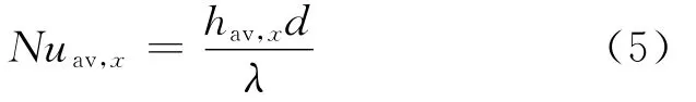
whereλis the thermal conductivity of air,and hav,xthe laterally-averaged convective heat transfer coefficient.
The discharge coefficient,which is inversely proportional to the pressure drop across the coolant hole in the rib-roughened channel,is defined as

where p*is the coolant flow total pressure in the plenum chamber metered by apressure probe,p0the coolant flow static pressure at semi-confined channel outlet,approximately regarded as the ambient pressure.
In all experiments,the measured temperature difference(between the surface and ambient)is at least 10°C with an uncertainty of±2%.The uncertainty of the power supplied to the heater,is assumed to be the same as the uncer-tainty of the heat flux out of the heater,that is,approximately±6%.The uncertainty in the thermal conductivity of air,given the small temperature fluctuations,is estimated to be less than±2%.The uncertainty of the flow rate is about 1%.And the measured errors of pressure are estimated as±3%.Following the uncertainty analysis based on Moffat[24],the maximum uncertainty in the measurement of the average convective heat transfer is±8%.The uncertainty in discharge coefficient measurements is estimated in the order of±5%.
2.3 Baseline validation of single jet impingement
Baseline validation is made to provide checks on the present measurement apparatus and procedures.The baseline test aiming at a single round jet employed for this purpose matches that employed by Gao et al[9]with Rej=23 000and nozzle-to-plate distance of 2diameters.Fig.2presents the comparison of area-averaged Nusselt number profiles.Here the area-averaged Nusselt number is defined in terms of the region of radius(R)surrounding the jet impinging stagnation point.
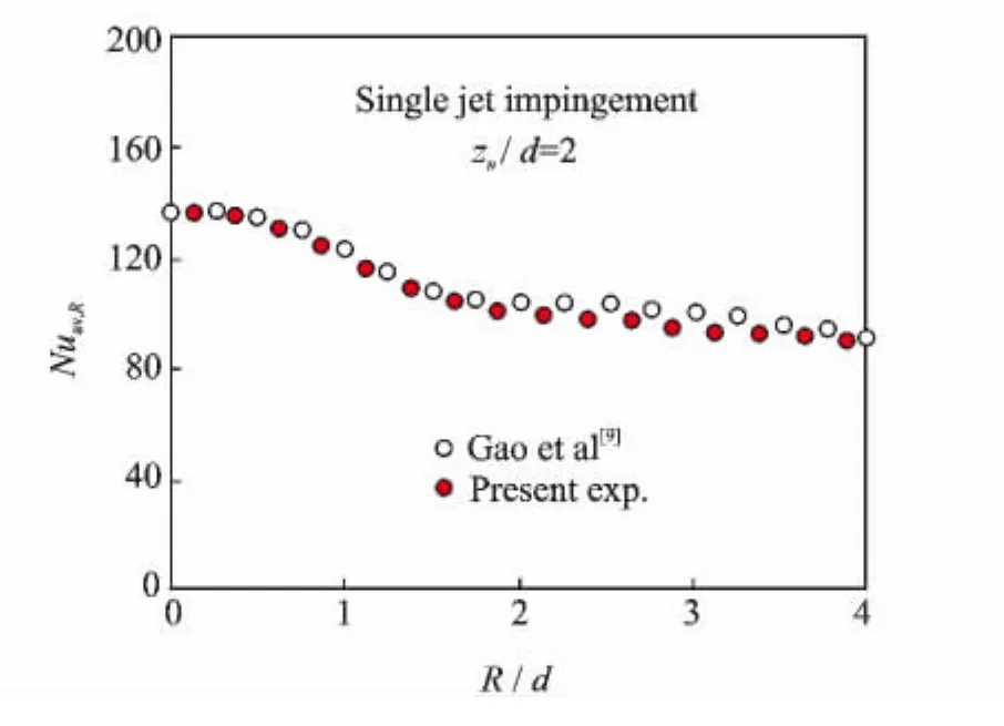
Fig.2 Baseline validation of area-averaged Nusselt numbers under single jet impingement
Fig.2illustrates that the averaged Nusselt number distributions on the impinged plate for both works exhibite the same behaviors.The good agreement of area-averaged Nusselt number distribution with Gao et al[9]validates the experimental procedures and apparatus employed in the present study.
3 Results and Discussion
3.1 Temperature distributions
Fig.3presents the temperature distributions on the constant heat-flux(q=5 000W/m2)heating foil surface under orifice-to-target spacing zn/d=2and spanwise pitch yn/d=3.Fig.4presents the temperature distributions for double-row case under zn/d=1,xn/d=3and yn/d=4.It seems that each impingement jet is responsible for a high heat transfer zone around the stagnation point.As the impingement Reynolds increases,the stagnation zone corresponding to each impinging jet is extended and the temperature on the stagnation zone is decreased obviously,which is coincidental perfectly to the previous studies.

Fig.3 Thermal images on target for single-row case(yn/d=3,zn/d=2)
3.2 Heat transfer coefficients
Heat transfer variations with the impingement distance zn/dhave been investigated extensively.A few laterally-averaged Nusselt number profiles extracted from these measurements are displayed in Fig.5.
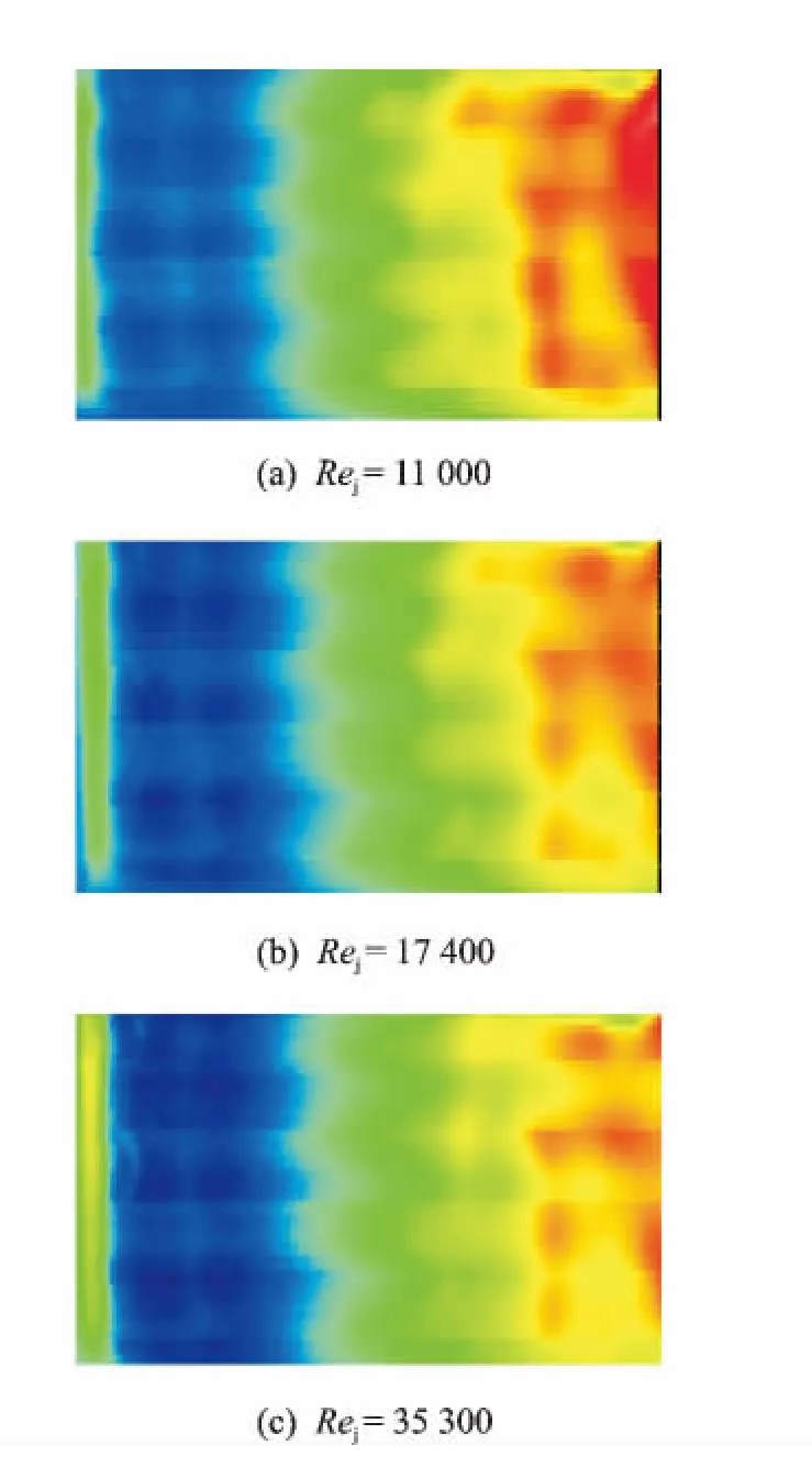
Fig.4 Thermal images on target for double-row case(xn/d=3,yn/d=4,zn/d=1)
As a consequence,it is notable that the im-pingement distance zn/d=2leads to the highest local heat transfer over the range of impingement distances tested for the single-row case.The heat transfer rate generated by the impingement distance zn/d=3is close to that for zn/d=2.A rapidly decrease of laterally-averaged Nusselt number appears under impingement distance zn/d=1.At this distance,the confinement effect is greatly penalizing due to the self-interaction of impinging jet and circular flow induced by the impinging jet near the closed side of semi-confined channel.This effect seems more vigorous under higher impingement Reynolds number.While for the double-row case,the optimum impingement distance is zn/d=1.This tendency is completely contrary to that of single-row case.With regard to the double-row case,the interaction of the jets from front row and rear row will play an important role in the heat transfer.In the case of zn/d=1,the stagnation zone corresponding to each row may be seriously affected by the other row.The junction effect may be superior to confinement effect,re-sulting in tremendous heat transfer enhancement under zn/d=1.

Fig.5 Laterally-averaged Nusselt numbers under different zn/d
Fig.6shows the influence of spanwise jet-tojet pitch(yn/d)on the laterally-averaged Nusselt number in the single-row case,while Fig.7shows the influence of streamwise jet-to-jet pitch(xn/d)on the laterally-averaged Nusselt number in the double-row case.As expected,under the same impingement Reynolds number,the laterallyaveraged Nusselt number is decreased with the increase of yn/d.With regard to the double-row case,the increase of xn/dextends the impinging cooling region.Besides,there is a little decrease of heat transfer coefficient in the region between two row impinging holes.
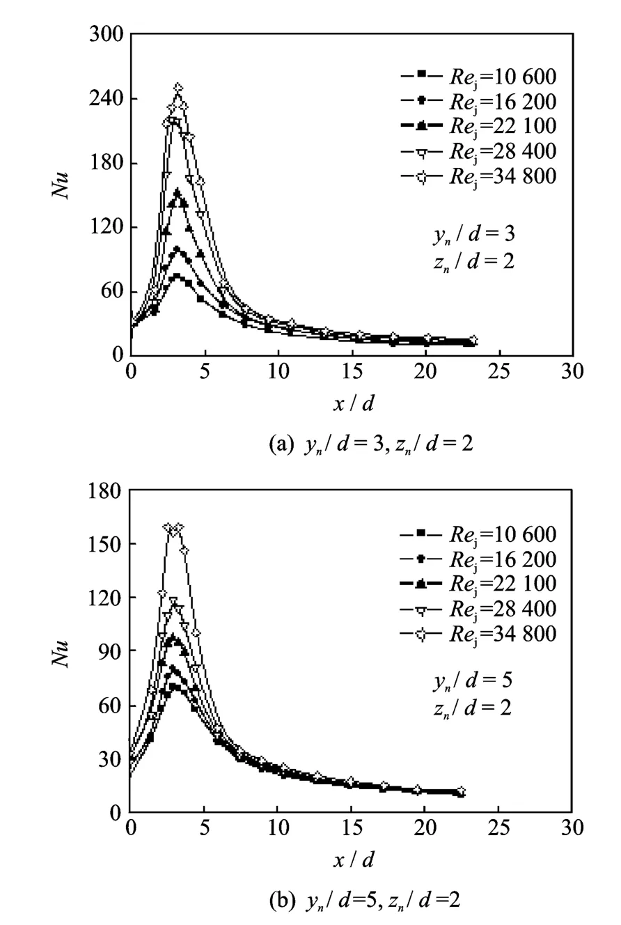
Fig.6 Laterally-averaged Nusselt numbers under different yn/d
By comparison of the single-row and doublerow cases,it is found that the laterally-averaged Nusselt number distributions within the zone of the first row of double-row case do not fit perfectly with the single-row case.Downstream of this region,heat transfer is drastically reduced in the single-row case since the impingement is not efficient any more whereas the impinging jets from the secondary row maintain high heat exchanges in the double-row configuration.
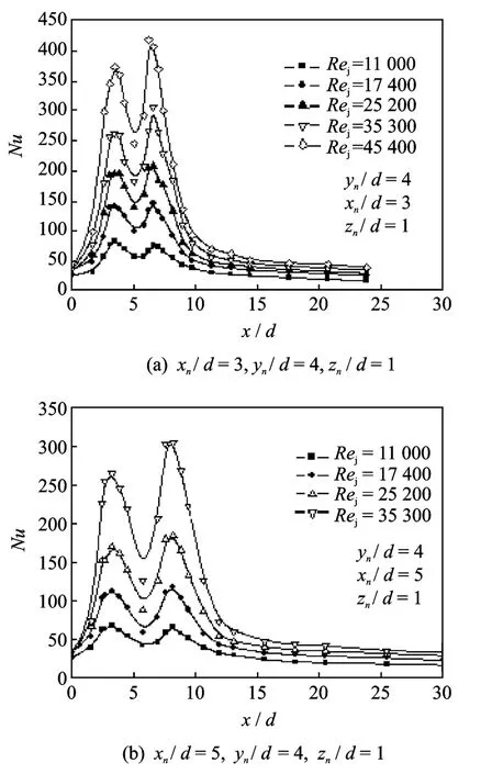
Fig.7 Laterally-averaged Nusselt numbers under different xn/d
It is noticed that the quantity of air used to impinge the target is associated with the number of impinging jets and the impingement Reynolds number.Therefore,one should not compare directly the averaged Nusselt numbers for different spanwise spacings from Figs.6,7.To evaluate the overall cooling efficiency of the different impingement configurations and to compare these different impingement cases directly,one can work at a fixed mass flow rate of coolant per unit area of cooled surface.In the present study,Gjis expressed as
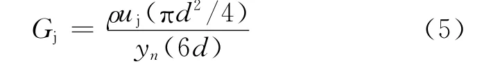
where Gjrepresents the air quantity devoted to the cooling of a given area(as seen in Fig.1)surrounding the impinging jet.
For the sigle-row jet impingement with zn/d=2,the area-averaged Nusselt numbers are ex-pressed as functions of Gjin Fig.8.It is interesting to find that the increase of impingement Reynolds number does not mean that the heat transfer rate will be certainly increased at a fixed value of Gj.As an example,for Gjfixed at 8.5,area-averaged Nusselt number is increased by 20%when changing the impingement configuration fromyn/d=4and Rej=28 400to yn/d=5and Rej=34 800.Furthermore the influence of yn/don area-averaged Nusselt number seems more significantly under the larger impingement Reynolds number.

Fig.8 Area-averaged Nusselt numbers vs.Gj
With regard to the relation of front row and rear row,it behaves more complicated.As we know,the jets from the first row impinging holes form uneven cross flow relative to the downstream jets,which deflects the downstream jets from the normal direction and weakens the convective heat transfer capacity of downstream jets.Simultaneously,the secondary jets behave as″disturbed pins″to the cross flow,which often enhances the convective heat transfer capacity of cross flow.The contradictory aspects are responsible for the complicated heat transfer features along downstream of the first row.In the case of zn/d=1,the impingement jets maintain stronger penetration in the surrounding fluid,which is weakly affected by the cross flow.At the same time,the cross flow is strengthened more obviously,so that the heat transfer enhancement shows advantageous in the region corresponding to the secondary row.While in the case of a larger zn/d,the jet penetration is decadent to be easily deflected by the cross flow and the convective heat transfer of the cross flow is also weaken,and the laterally-averaged Nusselt number is thus reduced on the second row compared with the peak Nusselt number on the first row.
3.3 Discharge coefficients
The discharge coefficient is inversely proportional to the pressure drop between the jet inlet and the channel outlet.Fig.9presents the influence of zn/d on the discharge coefficients in the single-row case.It is shown that the impingement distance zn/d=1leads to the lowest discharge coefficient over the range of impingement distances tested for the single-row case,which indicates that the pressure drop for this situation is the biggest.By comparison,the influence of zn/don the discharge coefficients is more obvious when the spanwise jet-to-jet pitch is smaller.
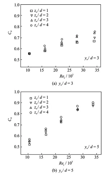
Fig.9 Discharge coefficients vs.Rejunder different zn/d
The influence of yn/don the discharge coefficients is shown in Fig.10.It is evident that yn/d has an important effect on the discharge coeffi-cient in the single-row case.When the spanwise jet-to-jet pitch is smaller,the interaction of the adjacent jets will be more intensive,owing to the increases of flow loss and a smaller discharge coefficient.As it can be seen from the figures,the influence is more significant in the higher impingement Reynolds number.
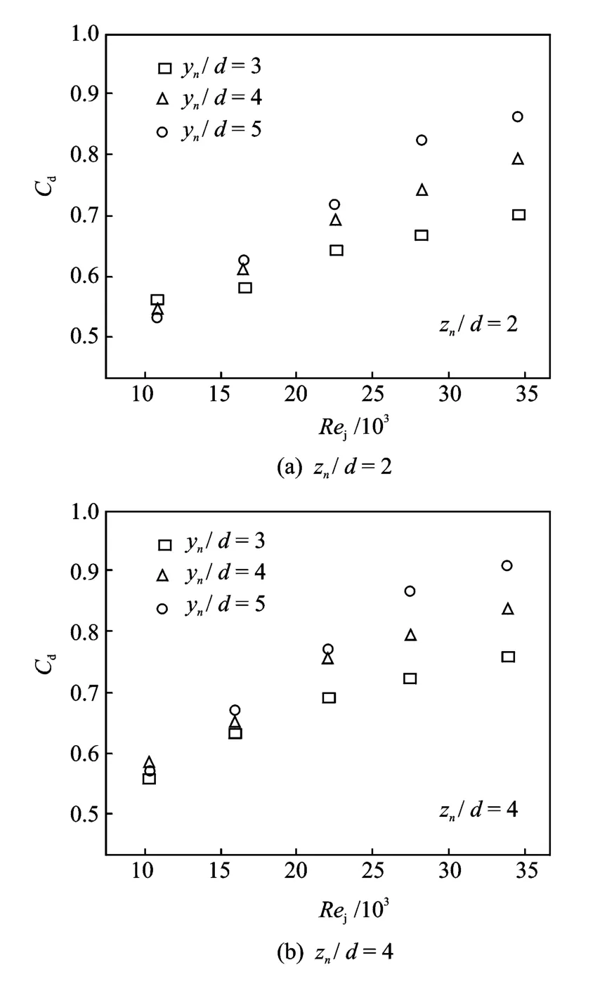
Fig.10 Discharge coefficients vs.Rejunder different yn/d

Fig.11 Comparison of discharge coefficients
Fig.11presents the comparison of discharge coefficients between single-row case and double-row case.It can be found that the discharge coefficient in the double-row case decreases compared with that of the single-row case at the same impingement Reynolds number.Due to the interaction of jets between adjacent streamwise rows,the flow loss inside the channel increases,which is contributed to the decrease of the discharge coefficient.
4 Conclusions
Experimental investigation is conducted to investigate the flow and heat transfer performances of impingement cooling inside semi-confined channel.Effects of impingement Reynolds number,orifice-to-target spacing and hole pitch on the convective heat transfer coefficient and discharge coefficient are revealed.The results are summarized as follows:
(1)The impingement distance zn/d=2leads to the highest local heat transfer over the range of impingement distances tested for the single-row case.The impingement heat transfer is enhanced with the increase of impinging Reynolds number or the decrease of spanwise jet-to-jet pitch.
(2)The laterally-averaged Nusselt number distributions within the zone of the first row of double-row case do not fit perfectly with the single-row case.The optimum impingement distance is zn/d=1in the double-row case.And the laterally-averaged Nusselt number is reduced on the second row compared to the first row at larger impingement distance.
(3)The spanwise jet-to-jet pitch has an important effect on the discharge coefficient.A smaller jet-to-jet pitch generally results in a lower discharge coefficient.This influence is more significant under the higher impingement Reynolds number.The discharge coefficient in the doublerow case is decreased relative to the single-row case at the same impingement Reynolds number.
[1] Leger B,Miron P,Emidio J M.Geometric and aerothermal influences on multi-holed plate temperature:application on combustor wall[J].International Jour-nal of Heat and Mass Transfer,2003,46:1215-1222.
[2] Facchini B,Surace M,Tarchi L.Impingement cooling for modern combustors:experimental analysis and preliminary design[R].ASME Paper GT 2005-68361,2005.
[3] Viskanta R.Heat transfer to impinging isothermal gas and flame jets[J].Experimental Thermal and Fluid Science,1993,6:111-134.
[4] Weigand B,Spring S.Multiple jet impingement—A Review[J].Heat Transfer Research,2011,42:101-142.
[5] Goldstein R J,Behbahani A I.Impingement of a circular jet with and without cross flow[J].International Journal of Heat and Mass Transfer,1982,25:1377-1382.
[6] Lee D,Greif R,Lee S,et al.Heat transfer from a flat plate to a fully developed axisymmetric impinging jet[J].ASME J Heat Transfer,1995(117):772-776.
[7] Colucci D W,Viskanta R.Effect of nozzle geometry on local convective heat transfer to a confined impinging air jet[J].Experimental Thermal and Fluid Science,1996,13:71-80.
[8] Brignoni L A,Garimella S V.Effects of nozzle-inlet chamfering on pressure drop and heat transfer in confined air jet impingement[J].International Journal of Heat and Mass Transfer,2000,43:1133-1139.
[9] Gao N,Sun H,Ewing D.Heat transfer to impinging round jets with triangular tabs[J].International Journal of Heat and Mass Transfer,2003,46:2557-2569.
[10]Alekseenko S V,Bilsky A V,Dulin V M,et al.Experimental study of an impinging jet with different swirl rates[J].Int J Heat Fluid Flow,2007(28):1340-1359.
[11]Katti V,Prabhu S V.Heat transfer enhancement on a flat surface with axisymmetric detached ribs by normal impingement of circular jet[J].International Journal of Heat and Fluid Flow,2008,29:1279-1294.
[12]Koseoglu M F,Baskayab S.The role of jet inlet geometry in impinging jet heat transfer,modeling and experiments[J].International Journal of Thermal Science,2010,49:1417-1426.
[13]Violato D,Ianiro A,Cardone G,et al.Three-dimensional vortex dynamics and convective heat transfer in circular and chevron impinging jets[J].International Journal of Heat and Fluid Flow,2012,37:22-36.
[14]Yu Y Z,Zhang J Z,Xu H S.Convective heat transfer by a row of confined air jets from round holes equipped with triangular tabs[J].International Journal of Heat and Mass Transfer,2014,72:222-233.
[15]Garimella S V,Rice R A.Confined and submerged liquid jet impingement heat transfer[J].ASME Journal of Heat Transfer,1995,117:871-877.
[16]Fitzgerald J A,Garimella S V.A study of the flow field of a confined and submerged impinging jet[J].International Journal of Heat and Mass Transfer,1998,41:1025-1034.
[17]Angibletti M,Di Tommaso R M,Nino E,et al.Simultaneous visualization of flow field and evaluation of local heat transfer by transitional impinging jet[J].International Journal of Heat and Mass Transfer,2003,46:1703-1713.
[18]Zhang J Z,Li Y K,Tan X M,et al.Numerical computation and experimental investigation on local convective heat transfer characteristics for jet array impingement[J].Chinese Journal of Aeronautics,2005,25:339-342.
[19]Wang T,Lin M J,Bunker R S.Flow and heat transfer of confined impingement jets cooling using a 3-D transient liquid crystal scheme[J].International Journal of Heat and Mass Transfer,2005,48:4887-4903.
[20]Parida P R,Ekkad S V,Ngo K.Experimental and numerical investigation of confined oblique impingement configurations for high heat flux applications[J].International Journal of Thermal Science,2011,50:1037-1050.
[21]Zhang J Z,Gao S,Tan X M.Convective heat transfer on a flat plate subjected to normally synthetic jet and horizontal forced flow[J].International Journal of Heat and Mass Transfer,2013,57:321-330.
[22]Tan X M,Zhang J Z.Flow and heat transfer characteristics under synthetic jets impingement driven by piezoelectric actuator[J].Experimental Thermal and Fluid Science,2013,48:134-146.
[23]Carlomagno G M,Cardone G.Infrared thermography for convective heat transfer measurements[J].Experiments in Fluids,2010,49:1187-1218.
[24]Moffat R J.Describing the uncertainties in experimental results[J].Experimental Thermal and Fluid Science,1988,1:3-17.
[25]Goldstein R J,Seol W S.Heat transfer to a row of impinging circular air jets including the effect of entrainment[J].International Journal of Heat and Mass Transfer,1991,34:2133-2146.
猜你喜欢
杂志排行

Transactions of Nanjing University of Aeronautics and Astronautics的其它文章
- Lattice Boltzmann Flux Solver:An Efficient Approach for Numerical Simulation of Fluid Flows*
- Flapping Characteristics of 2DSubmerged Turbulent Jets in Narrow Channels*
- Critical Length of Double-Walled Carbon Nanotubes Based Oscillators*
- Identification of Time-Varying Modal Parameters for Thermo-Elastic Structure Subject to Unsteady Heating*
- Optimal Delayed Control of Nonlinear Vibration Resonances of Single Degree of Freedom System*
- Dynamics of Rotor Drop on New Type Catcher Bearing*