HYBRID AIRFOIL DESIGN FOR FULL-SCALE ICE ACCRETION TEST
2013-12-02GuoTao郭涛ZhuChengxiang朱程香ZhuChunling朱春玲
Guo Tao(郭涛),Zhu Chengxiang(朱程香),Zhu Chunling(朱春玲)
(1.College of Aerospace Engineering,Nanjing University of Aeronautics and Astronautics,Nanjing,210016,P.R.China;2.Key Laboratory of Fundamental Science for National Defense Advanced Design Technology of Flight Vehicle,Nanjing University of Aeronautics and Astronautics,Nanjing,210016,P.R.China)
INTRODUCTION
It has been long known that ice formation on aircraft airfoils has adverse effects on aerodynamics and poses a major threat to aircraft safety[1-3].Ice accretion makes gross change in the geometry.But ice accretion of full-scale airfoils cannot be tested in existing icing tunnels due to its blocking.One way is to design a smaller hybrid airfoil with simulated character of icing.The hybrid airfoil[4-7]retains the leading edge of full-scale airfoil with shortened aft-section,and thereby has a shorter overall chord.After using suitably computational techniques,the hybrid airfoil can be tested under same conditions to produce simulated ice accretion with full-scale airfoil.Therefore,it makes the existing icing-tunnel useful,and it can also achieve the simulated droplet impingement area and ice accretion with full-scale airfoils.This methodology is primarily valid for incompressible and inviscid flow.
In this paper,a method is presented to design the hybrid airfoil with the reverse design method to match the ice accretion of the full-scale airfoil.It is an extension of the design method developed by Saeed,et al for hybrid airfoil.
1 DESIGN PROCEDURE OF HYBRID AIRFOIL
The following tools are extensively used in the design and analysis of the full-scale and hybrid airfoils in this study.
FENSAP-ICE[8-9]is a fully three-dimensional(3D)icing simulation system,and has five modules that form a complete,versatile,flexible in-flight icing system.Three of them are used in the study:
FENSAP is a 3Dfinite element-based Navier-Stokes solver.
DROP3Dis a 3Dfinite element-based Eulerian droplets impingement solver.
ICE3Dis a 3Dfinite volume ice accretion and water runback solver.
Fig.1outlines the design method for hybrid airfoil.Firstly mesh the flow field of the full-scale airfoil with the software ICEM.Flow field and droplet impingement calculation can be performed on the full-scale airfoil at different attack angles.Then obtain the pressure distribution and the collection efficiency.Finally,compare the limit of the impingement and the slat,and choose the maximum of them as the limit of the nose.

Fig.1 Hybrid airfoil design procedure
The extent of the common nose section for the present tests is illustrated in Fig.1as an example.The original hybrid airfoil can be designed by lining the end of nose and the chord point of hybrid airfoil.After that grid around the hybrid airfoil can be created,and flow field and droplet impingement calculation can be performed.Then the pressure distribution and collection efficiency can be obtained,and those of the nose section between the full-scale and hybrid airfoils are compared.
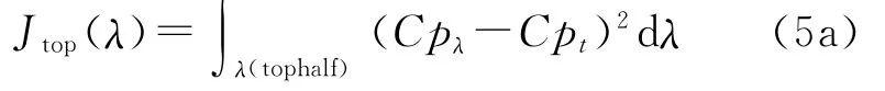
In the hybrid design method,an iterative process is used to update the contour of the after body until the droplet impingement characteristics and pressure distribution of the nose section match those of the full-size airfoil.An inverse method[10]for shape generation and genetic algorithm for optimization is used in airfoil shape optimization.A Newton iteration scheme is built into the inverse method to impose geometry con-straints that aid in reducing the design space and thereby improve the efficiency of the optimization method.The airfoil geometries are generated by an inverse method from pressure distribution parameters.Suppose a surface pressure coefficient distribution of a target airfoil as the initial one to reach the target.The objective function used for this type of problem is as follows

where Cpλand Cptare the current and the target pressure coefficient distributions along the airfoil.The fitness function of a generated airfoil is proportional to the inverse of the objective function,i.e.

Therefore,the problem becomes a typical maximization problem and as the fitness value goes to infinity,the two Cpdistributions become identical.An important issue in implementing ge-netic algorithm is the representation of the airfoil geometry.Herein,the mth order Bezier curve representation with m+1control points is used
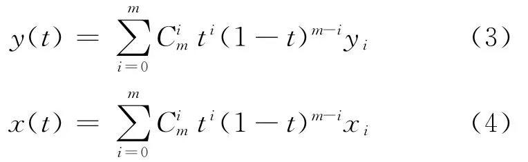
Coordinates(0,0)and(X,0)are the leading and trailing end points.The real parameter t variesCoordinates(xi,yi)are the control points which define the profile,where xiare considered as fixed,and only the yiordinates of the control points are processed in the genetic algorithm.Chromosomes representing the airfoil surface are split into the top and bottom sections.Airfoil design is achieved by dividing the airfoil into a number of segments.Fig.2shows Bezier curve representation of the airfoil.For the Bezier representations of airfoil surfaces,13control points are used.
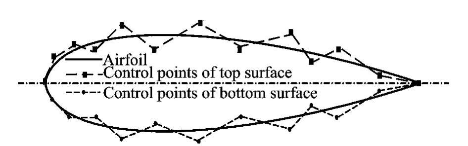
Fig.2 Bezier curve representation of airfoil
In implementing the distribution strategies,top and bottom surfaces of the airfoil are considered separately.That leads to two chromosomes representing the airfoil,i.e.
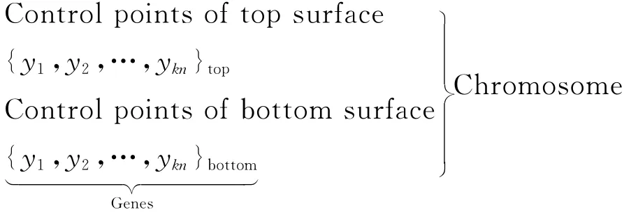
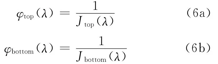
Consequently,objective function and fitness values for the chromosomes representing the top and bottom halves are calculated separately.Namely,the objective functions for top half and bottom half surfaces are

Corresponding fitness values for the top half and the bottom half surfaces are
The chromosome(including top half and bottom half surfaces)with the greatest fitness value is carried into the next generation as a result of elitism,similarly the best group of chromosomes of the both top half and bottom half surfaces,too.A viscous-flow analysis is used to determine proper fitness values for candidate airfoils based on preset performance criteria. A selection process based on fitness values(100 000,10 000 and 1 000)is carried out for the chromosome groups.The principal performance criteria employed in design process is that the maximum pressure coefficient difference that between the target and the designed one is smaller than 0.05.The local pressure distributions over the nose section and the stagnation point location on both the hybrid and full-scale airfoils are then compared.If the desired pressure distribution over the nose section is not achieved,the aft-section of the hybrid airfoil is redesigned and again merged with nose section to form a new hybrid airfoil.The flow over the new hybrid is then analyzed and compared with that over the full-scale airfoil.The process is repeated until the desired pressure distribution and the droplet impingement characteristics over the nose section are achieved.The attack angle at which the hybrid airfoil is designed to have the same droplet impingement distribution as the full-scale airfoil is the designed attack angle α.At this designed angleα,the hybrid airfoil and the full-scale airfoil have nearly the same pressure distribution and hence similar droplet impingement.The hybrid airfoil is iterated again,if necessary,until a good agreement in theβ-curve of the full-scale and hybrid airfoils is achieved.A flap system is used to indicate off-design attack angles.The use of a flap for full-scale simulation is restricted to low and moderate attack angles since at high absolute attack angles together with high flap deflections,the hybrid become susceptible to flow separation.
2 VALIDATIONS
One-dimensional chord of 1.8mfor the fullscale airfoil and 1.1mfor the hybrid airfoil is assumed.The full-scale airfoil of a modern aircraft is studied in this case.Hybrid airfoil is designed with the inverse method as discussed earlier.The two airfoils are illustrated in Fig.3.An angle 4°is chosen as the designed attack angle,and the other two angles 2°and 6°are also computed for comparison.A single icing condition is chosen to typify the icing condition on a commercial transport airplane.The icing condition for the analyses presented in this study is:Airspeed of 75m/s,static temperature of 263.75K,pressure of 101 325Pa,icing time of 300s,liquid water content of 0.5g/m3,and median volume diameter of 20 μm.The ice accretion calculations on the three configurations of airfoils at angles of 2°,4°and 6°are performed using the computational procedure described in the previous sections.

Fig.3 Comparison of full-scale with hybrid airfoils
The airfoil is discretized using a C-type grid as shown in Fig.4.The boundary conditions are defined as follows:A far-field boundary condition is imposed on the outer surfaces of the grid,and a no-slip boundary condition is imposed on the airfoil.Since the flow is viscous and turbulent,grid points are clustered on the airfoil to better capture the boundary layer and wake.For turbulence,select the Spalart-Allmaras model with low free stream turbulence(using a very low eddy/laminar viscosity ratio of 1×10⁻⁵).Turbulence is then only generated by the airfoil.Any roughness is not imposed for this calculation,thus corresponding to a clean airfoil.

Fig.4 Grids of full-scale and hybrid airfoils and detail

Fig.5 Pressure coefficient comparison at 2°
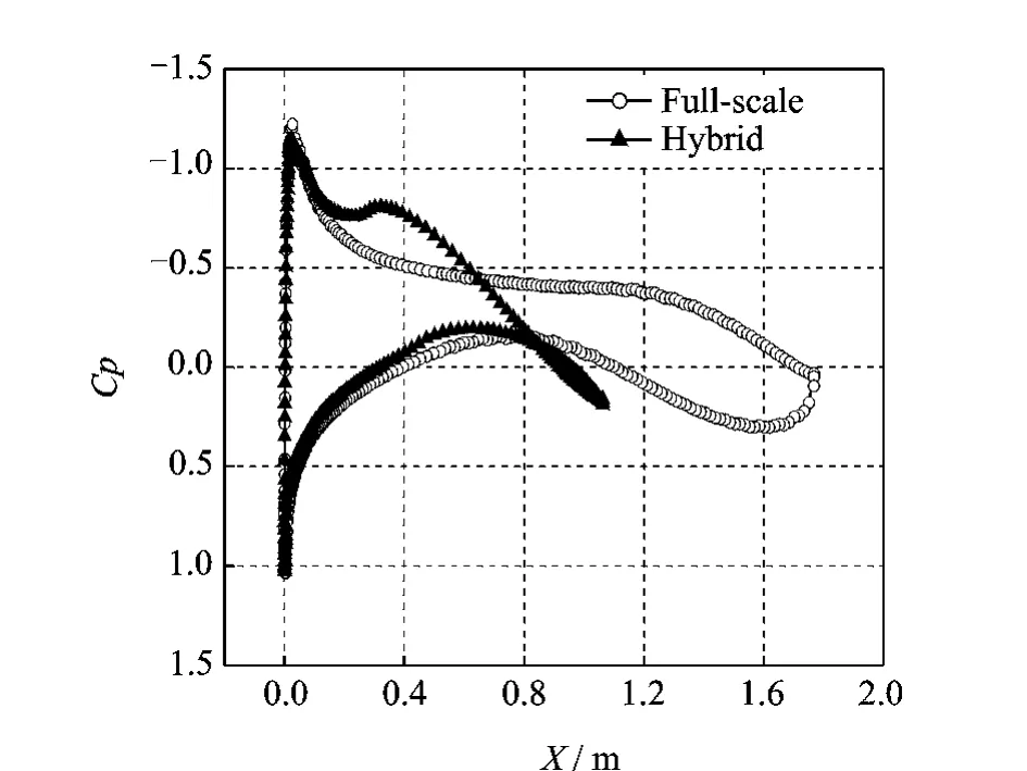
Fig.6 Pressure coefficient comparison at 4°
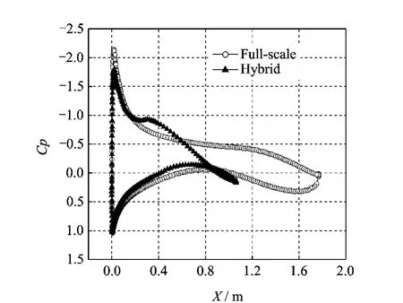
Fig.7 Pressure coefficient comparison at 6°
It is shown in Figs.5-7that the pressure coefficient curves for the full-scale and hybrid air-foils agree closely in the nose region at the designed angle of 4°.There is a difference in the region of the aft-section.Since ice accretion depends,most importantly,on the airfoil leadingedge geometry where the ice first accretes,the target is the nose section pressure distribution of the hybrid airfoil to match that of the full-scale airfoil.The difference of pressure distribution on after section has less influence on local collection efficiency and ice accretion.

Fig.8 Collection efficiency comparison at 2°
It is illustrated in Figs.8-10that the local collection efficiency curves for the full-scale and hybrid airfoils also agree closely at attack angles of 2°,4°and 6°.There is a little difference of collection efficiency in upper region of the airfoil due to the difference of pressure distribution of the upper region at the angle 2°.Also,there is a little difference of collection efficiency in lower region of the airfoil due to the difference of pressure distribution of the lower region at the angle 6°.The results show that the local collection efficiency depends on the pressure distribution.The key to obtain the matched collection efficiency is optimizing the hybrid airfoil to minimize the pressure coefficient difference of nose section between the hybrid and full-scale airfoils.
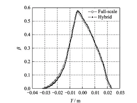
Fig.9 Collection efficiency comparison at 4°

Fig.10 Collection efficiency comparison at 6°
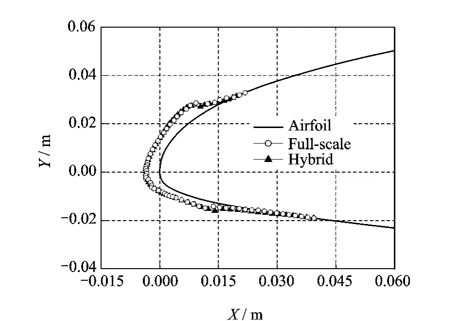
Fig.11 Ice accretions at 2°

Fig.12 Ice accretions at 4°
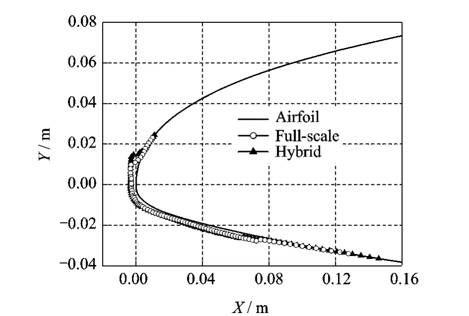
Fig.13 Ice accretions at 6°
It can be seen from Figs.11-13that the ice shape curves for the full-scale and hybrid airfoils agree closely at attack angles of 2°,4°and 6°.The limit of ice shapes is extended in the impingement region of the airfoil.There is only a little difference in upper and lower ice shape limits owing to the difference of collection efficiency of the impingement region.
3 CONCLUSION
A systematic study on hybrid airfoil design and ice accretions of full-scale and hybrid airfoils is conducted.It is found that there is a fairly good agreement in ice shapes for the full-scale and hybrid airfoils at all attack angles considered for all of the configurations studied.The results show the local collection efficiency most importantly depends on the pressure distribution of the nose of the two airfoils.It also shows that good agreement in flow field and droplet impingement can achieve a close agreement in ice shapes for the full-scale and hybrid airfoils.Results indicate that using the designed variables defining the pressure distribution in the inverse method has great potential for increasing the efficiency of airfoil shape optimization using genetic algorithms.
[1] Perkins P,Rieke W.Aircraft icing problems—After 50years[C]//31st Aerospace Sciences Meeting and Exhibit.Reno,NV:AIAA,1993,AIAA-1993-0392:1-2.
[2] Zhu Chengxiang,Sun Zhiguo,Fu Bin,et al.Effects of multi-dispersed droplet distribution on droplet impingement and ice accretion[J].Journal of Nanjing U-niversity of Aeronautics & Astronautics,2010,42(5):620-624.(in Chinese)
[3] Zhu Chengxiang,Fu Bin,Sun Zhiguo,et al.Calculation of wind turbine anti-icing heat lead[J].Journal of Nanjing University of Aeronautics & Astronautics,2011,43(5):701-706.(in Chinese)
[4] Saeed F,Selig M,Bragg M.Design of subscale airfoils with full-scale leading-edges for ice accretion testing[J].Journal of Aircraft,1997,34(1):94-100.
[5] Saeed F,Selig M,Bragg M.Hybrid airfoil design method to simulate full-scale ice accretion throughout agiven a-range[J].Journal of Aircraft,1998,35(2):233-239.
[6] Saeed F,Selig M,Bragg M.Hybrid airfoil design procedure validation for full-scale ice accretion simulation[J].Journal of Aircraft,1999,36(5):769-776.
[7] Saeed F.Hybrid airfoil design methods for full-scale ice accretion simulation[D].Urbana,IL:University of Illinois at Urbana-Champaign,1999.
[8] Héloise B,Francois M,Wagdi H G.FENSAP-ICE′s three-dimensional in-flight ice accretion module:ICE3D[J].Journal of Aircraft,2003,40(2):239-247.
[9] Nakakita K,Nadarajah S,Habashi W.Toward realtime aero-icing simulation of complete aircraft via FENSAP-ICE[J].Journal of Aircraft,2010,47(1):96-109.
[10]Gardner B A,Selig M.Airfoil design using agenetic algorithm and an inverse method [C]//41st Aerospace Sciences Meeting and Exhibit.Reno,Nevada:AIAA,2003,AIAA-2003-0043:2-4.
杂志排行

Transactions of Nanjing University of Aeronautics and Astronautics的其它文章
- FLEXURAL CAPACITY OF RC BEAM STRENGTHENED WITH PRESTRESSED C/AFRP SHEETS
- MINIMUM ATTRIBUTE CO-REDUCTION ALGORITHM BASED ON MULTILEVEL EVOLUTIONARY TREE WITH SELF-ADAPTIVE SUBPOPULATIONS
- OUTPUT MAXIMIZATION CONTROL FOR VSCF WIND ENERGY CONVERSION SYSTEM USING EXTREMUM CONTROL STRATEGY
- ACTIVE VIBRATION CONTROL OF TWO-BEAM STRUCTURES
- IMPROVED DOPPLER WARPING METHOD FOR AIRBORNE RADAR WITH NON-SIDELOOKING ARRAY
- MULTI-OBJECTIVE PROGRAMMING FOR AIRPORT GATE REASSIGNMENT