IMPROVED DOPPLER WARPING METHOD FOR AIRBORNE RADAR WITH NON-SIDELOOKING ARRAY
2013-12-02ZhaoJun赵军ShenMingwei沈明威ZhuDaiyin朱岱寅ZhuZhaoda朱兆达
Zhao Jun(赵军),Shen Mingwei(沈明威),Zhu Daiyin(朱岱寅),Zhu Zhaoda(朱兆达)
(1.Aeronautic Ordnance Engineer Department,The First Aeronautical Institute of Air Force,Xinyang,464000,P.R.China;2.College of Computer &Information,Hohai University,Nanjing,211100,P.R.China;3.College of Electronic and Information Engineering,Nanjing University of Aeronautics and Astronautics,Nanjing,210016,P.R.China)
INTRODUCTION
Space time adaptive processing(STAP)techniques are used in airborne radar systems to improve the performance of detecting slow-moving targets.However,traditional STAP approaches almost exclusively consider airborne radar with sidelooking uniform linear array and seldom nonsidelooking airborne radar(non-SLAR).In fact,the clutter spectra of non-SLAR change with range and interference in different range cells are not independent identical distributed (IID)with interference in cell under test(CUT).Since the premise of statistical STAP approaches is to have sufficient training IID samples with interference to estimate the covariance matrix of CUT,the performance of traditional statistical STAP methods degrades dramatically.
In the last few years,a number of contributions have been reported[1-11]where the clutter range-dependency problem is largely addressed and different approaches are proposed.Among them,compensation techniques are the effective ones to remove the non-consistency characteristics of non-SLAR such as Doppler warping (DW)[1-2]and angle-Doppler compensation (ADC)[3-4]method.These technologies are demonstrated to recover the performance degradation induced by particular geometry in many cases.However,they still suffer from significant loss due to the residual clutter dispersion in the training sample data set.
Therefore,a novel strategy of the training sample processing is proposed as an improved DW method to compensate the spectrum in the mainlobe and clutter trajectory variability of non-SLAR over multiple Doppler bins.Simulation results illustrate the effectiveness of the proposed method.
1 CLUTTER PROPERTIES OF NON-SLAR
Consider a pulse Doppler radar situated on an airborne platform,which is moving at a constant velocity of v,as shown in Fig.1.The radar antenna is a uniformly linear array (ULA)consisting of Nelements.And Kpulses are collected in a coherent processing interval.The placed angle between the axis of the array and the flight direction isα,andβis the cone angle between the axis and the clutter scatter at elevationθand azimuth φ.The Doppler frequency fdand the space frequency fsof the scatter can be denoted as
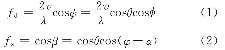
whereψis the cone angle between the flight direction and the array,which satisfies the equation cosψ=cosθcosφ,andλthe RF wavelength.
From Eqs.(1-2) we obtain the angle-Doppler relationship of clutter scatter after some manipulations
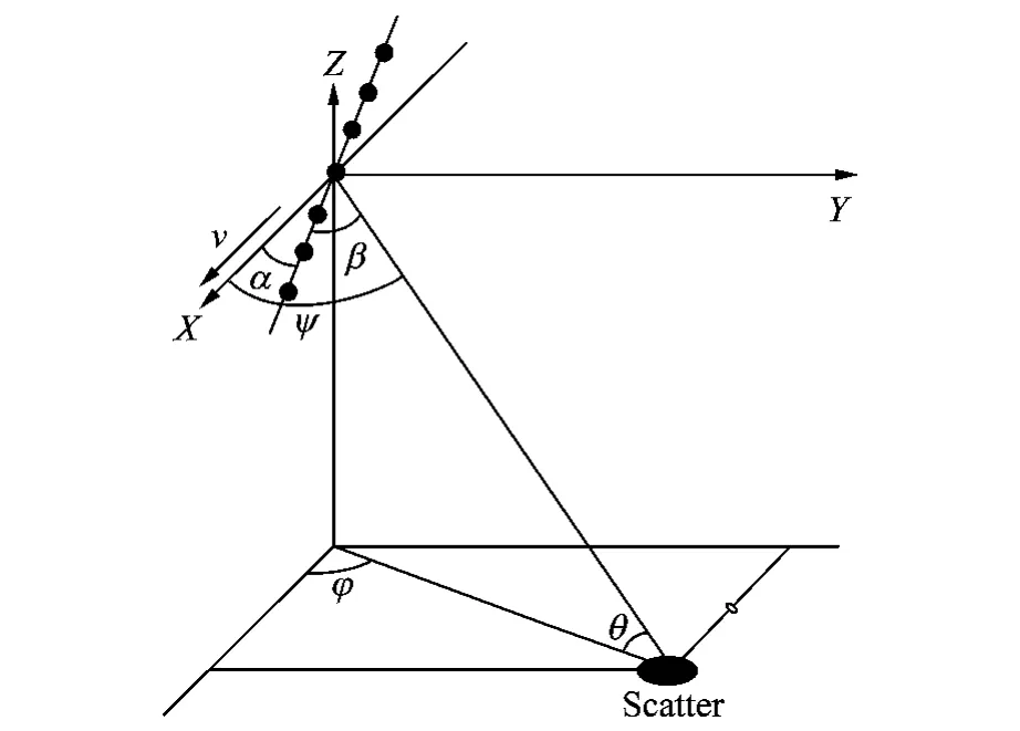
Fig.1 Geometry of airborne radar with ULA and clutter scatter
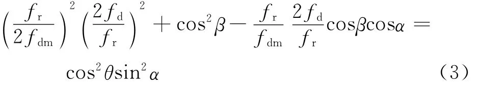
where fdm=2v/λis the maximum Doppler frequency and frthe pulse repetition frequency.
From Eq.(3),for a sidelooking array,the placed angle becomesα=0°and the clutter power spectra are overlapped straight lines in the fdcosβplane.But for a non-SLAR,the placed angle satisfies 0<α<90°and the power spectra are a set of ellipse with constant rotated angles.The comparison of clutter spectra distribution between sidelooking arrays and non-SLAR arrays at the slant distance Rlof 10,15,40,400km is given in Fig.2.

Fig.2 Comparison of clutter spectrum distribution of ULA
From Fig.2,we can see the clutter trajectories of sidelooking arrays are stationary over a range in angle-Doppler space while those of the non-SLAR arrays change with the change of range.An adaptive weight of STAP method trained from a set of range gates in the vicinity of CUT will not be usable for null clutter in the CUT since the location of clutter for a given Doppler bin varies with the change of range,thus the performance of statistical STAP methods degrade.
2 STAP METHOD FOR NON-SLAR
2.1 Processing with DW method
Suppose the cone angle of main beam isβand 2Ltarget-free echo vectors Xl(l=-L,…,-1,1,…,L)in vicinity of CUT,defined in the 0th range cell,are collected as training samples to estimate the interference covariance matrix.From Eq.(3),the normalized Doppler frequency difference between the lth secondary range cell and the 0th range cell in the mainlobe direction is

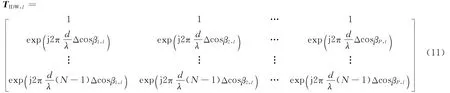
The transformation matrix for the lth range gate of DW algorithm can be expressed as
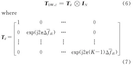
and INis the N×Nidentity matrix.
The lth secondary data processed with DW method is

The clutter spectra distribution of non-SLAR(α=60°)after processing with DW method is given in Fig.3.
After preprocessed by DW algorithm,the clutter spectra at secondary range cells are collocated and the clutter in the centers of main beam is homogeneous,but in the directions of the sidelobe,there is still a large clutter dispersion.In order to further reduce the clutter range-depend-ency of non-SLAR,an improved DW (IDW)method is proposed.
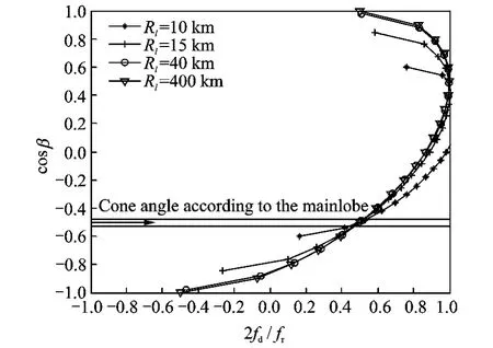
Fig.3 Distribution of clutter spectrum with DW method
2.2 IDW method
The main idea of IDW method is to further reduce the residual dispersion in the sidelobe area of non-SLAR.Multiple Doppler bins,which lie in the vicinity of the Doppler bin points to spectrum center of CUT,are firstly selected,and a subsequent space angle compensation is performed to align the trajectory of lth range gate with that of CUT in each Doppler bin.Compared with DW method,clutter dispersion processed with IDW method is further reduced as the trajectories have been co-located in multiple Doppler bins.
The lth secondary data processed with DW method XDW,lis transformed to a N ×Kmatrix X′DW,land then FFT is performed over the time dimension.According to Eq.(3),for the lth secondary data,the cone angle changes at the frequency Fpis
马国平放下望远镜,当机立断地命令陈山利、牛力军、恭建兵三人迂回过去,堵住日军下山路,他亲率人马前后夹击

whereβp,lis the cone angle correspond to the pth Doppler bin for the lth range cell,Fpthe center frequency in the pth Doppler bin,p= -P,…,-1,1,…,P,where 2Pdenotes the total number of the Doppler bins and F0=fd0.The compensation factor of IDW method for the lth secondary range gate can be denoted as
Then the processed secondary data is

where X′DW,lis the transformation of X′DW,lafter FFT is performed.
Finally,inverse fast Fourier transformation(IFFT)is performed over the columns ofX′IDW,land X′IDW,lare obtained.And then N×Kmatrix X′IDW,lis transformed back to a NK ×1vector.The principle of IDW algorithm is shown in Fig.4.
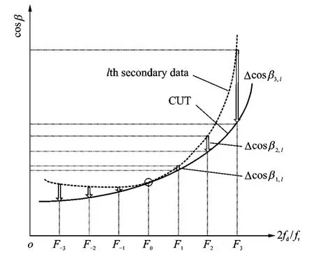
Fig.4 Principle of IDW method
The IDW algorithm applied at the lth secondary range cell can be summarized in the following steps:
(1)Apply the compensation factor TDW,lof the DW algorithm to the lth secondary range cell and get the processed data XDW,l=THDW,lXlwith DW method;
(2)Transform XDW,linto a N ×K matrix X′DW,land perform a FFT over the time dimension;
(4)Perform Hadamard inner product with TIDW,landX′DW,l,and obtain the compensated data X′IDW,l=TIDW,l⊙X′DW,l;
(5)Perform an IFFT over the processed matrixX′IDW,land then transform it back into a NK×1vector.
3 SIMULATION RESULTS
Simulation parameters are given in Table 1,CUT is assumed to lie in Rs=12km and 128data from range cell adjacent to CUT are collected as training samples to estimate the covariance.A reduced dimension method,namely 3DT-SAP algorithm[12]is used to reduce the dimension of processed data,The minimum variance power spectrum[13]comparison of optimum processor(OPT)[13],IDW,ADC,DW and sample matrix inversion(SMI)[13]is given in Fig.5,comparisons of improved factor(IF)[13]are shown in Fig.6.
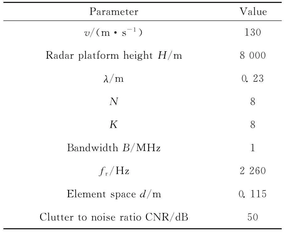
Table 1 Parameters in simulation
Fig.5shows all clutter spectra of compensation STAP methods,including IDW,ADC and DW,are significant narrower than spectra with-out compensation(SMI).Apparently,IDW demonstrates a further improvement with respect to both ADC and DW method because the latter only reduces the clutter dispersion in one Doppler bin while the former in multiple Doppler bins.This fact is also confirmed in Fig.6,where the improved factor of IDW outperforms 2.92dB than ADC method and 10.02dB than DW method.The comparison of the required training samples and computation load of compensation STAP methods are given in Tables 2-3.
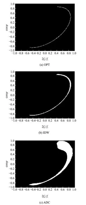
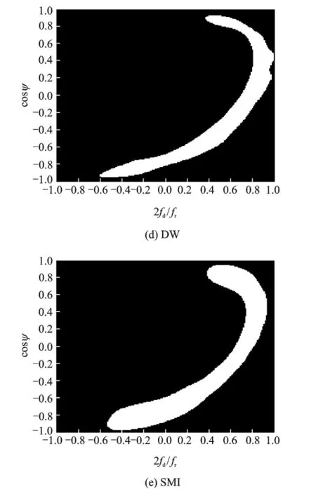
Fig.5 Comparison of clutter spectrum of compensation STAP methods for non-SLAR(α=60°)
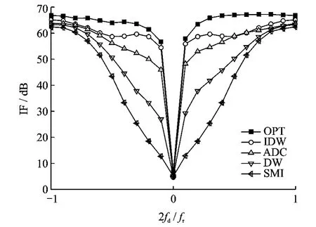
Fig.6 Comparison of IF of compensation STAP methods for non-SLAR(α=60°)
As the non-homogeneity of non-SLAR increases with the placed angleα,the benefit of IDW method increases too.Under the condition ofα=30°,IF of IDW outperforms 4.03dB than that of DW method.Whenα=60°andα=90°,the values increase to 10.02dB and 13.14dB.To further improve the performance of IDW method,more Doppler bins to compensation should be adopted,but this will lead to an increasingly heavy computation load.
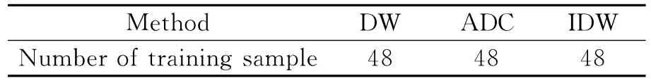
Table 2 Comparison of training samples of compensation STAP methods
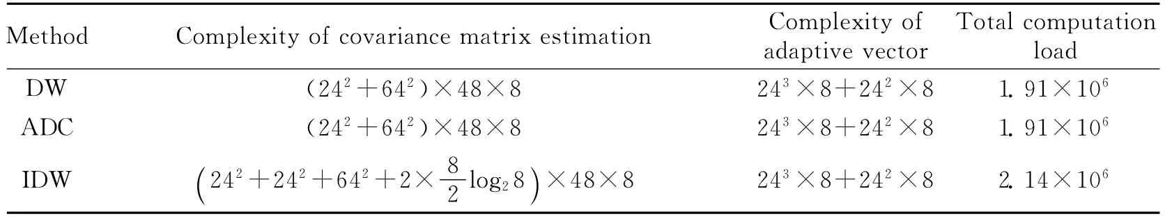
Table 3 Comparison of computation load of compensation STAP methods
4 CONCLUSION
A novel compensation STAP algorithm is presented to mitigate the effects of non-SLAR clutter spectral dispersion.The proposed approach is based on the idea of re-aligning the clutter spectra trajectories in different range gates after the spectra have been co-located in the direction of the mainlobe.Simulation results show the proposed method can more effectively alleviate the non-stationary characteristics of clutter and perform than traditional compensation methods do.
[1] Kogon S M,Zatman M.Bistatic STAP for airborne radar systems[C]//Proceedings of IEEE SAM 2000.Lexington,MA,USA:MIT Lincoln Laboratory,2001:13-14.
[2] Gong Qingyong,Zhu Zhaoda.Study on clutter suppression algorithm for Airborne radar with non-sidelooking Arrays[J].Journal of Electronics and Information Technology,2009,31(4):977-980.(in Chinese)
[3] Himed B,Zhang Y H,Hajjari A.STAP with angle-Doppler compensation for bistatic airborne radar[C]//Proc of the IEEE National Radar Conf.Long Beach,CA,USA:IEEE,2002:311-317.
[4] Jaffer A G,Ho P T,Himed B.Adaptive compensation for conformal array STAP by configuration parameter estimation[C]//Proc of the IEEE National Conf.Verona,NY,USA:IEEE,2006:731-736.
[5] Lapierre F D,Droogenbroeck M V,Verly J G.New methods for handling the dependence of the clutter spectrum in non-sidelooking monostatic STAP radars[C]//Proc of the IEEE Acoustics,Speech,and Signal Processing Conf. HongKong,China:IEEE,2003:73-76.
[6] Yang Bo,Zhou Yiyu,Huang Zhitao.Range-dependence compensation for bistatic STAP based on range ambiguity[J].Acta Electronica Sinina,2010,29(3):555-561.(in Chinese)
[7] Zatman M.Circular array STAP[J].IEEE Trans on AES,2000,36(2):510-517.
[8] Li Ming,Liao Guisheng.Algorithm utilizing derivative based updating to compensate clutter range dependence for bistatic airborne radar[J].Journal of E-lectronics &Information Technology,2009,31(9):2059-2064.(in Chinese)
[9] Jaffer A,Himed B,Ho P T.Estimation of range-dependent clutter covariance by configuration parameter estimation[C]//Proc of the IEEE Int Radar Conf.Arlington,VA,USA:IEEE,2005:596-601.
[10]Jaffer A,Ho P T,Himed B.Adaptive compensation for conformal array STAP by configuration parameter estimation[C]//Proc of the IEEE National Radar Conf.Verona,NY,USA:IEEE,2006:731-736.
[11]Nert X,Acheroy M,Verly J G.Maximum likelihood range dependence compensation for STAP[C]//Proc of the IEEE Int Conf on Acoustics,Speech and Signal Processing.Honolulu,Hawaii,USA:IEEE,2007:913-916.
[12]Fa R,Lamare R C,Wang L.Reduced-rank STAP schemes for airborne radar based on switched joint interpolation,decimation and filtering algorithm[J].IEEE Trans on SP,2010,58(8):4182-4194.
[13]Klemm R.IEE radar,sonar,navigation and avionics series 12:Principle of space-time adaptive processing[M].London:IEE Press,2002.
猜你喜欢
杂志排行

Transactions of Nanjing University of Aeronautics and Astronautics的其它文章
- FLEXURAL CAPACITY OF RC BEAM STRENGTHENED WITH PRESTRESSED C/AFRP SHEETS
- MINIMUM ATTRIBUTE CO-REDUCTION ALGORITHM BASED ON MULTILEVEL EVOLUTIONARY TREE WITH SELF-ADAPTIVE SUBPOPULATIONS
- OUTPUT MAXIMIZATION CONTROL FOR VSCF WIND ENERGY CONVERSION SYSTEM USING EXTREMUM CONTROL STRATEGY
- ACTIVE VIBRATION CONTROL OF TWO-BEAM STRUCTURES
- DISCONTINUOUS GALERKIN TIME DOMAIN METHOD FOR SOI THIN-RIDGE WAVEGUIDE PROBLEM
- MULTI-OBJECTIVE PROGRAMMING FOR AIRPORT GATE REASSIGNMENT