Obstacle detection using multi-sensor fusion*
2013-11-01QingLinYoungjoonHanNamkiLeeHwanikChung
Qing Lin, Youngjoon Han, Namki Lee, Hwanik Chung
(1. Department of Electronic Engineering, Soongsil University, Seoul 156-743, Korea;2. Departmen of Computer Science and Information, Kyungbok University, Seoul 156-743, Korea)
Obstacle detection using multi-sensor fusion*
Qing Lin1, Youngjoon Han1, Namki Lee1, Hwanik Chung2
(1. Department of Electronic Engineering, Soongsil University, Seoul 156-743, Korea;2. Departmen of Computer Science and Information, Kyungbok University, Seoul 156-743, Korea)
This paper presents an obstacle detection approach for blind pedestrians by fusing data from camera and laser sensor. For purely vision-based blind guidance system, it is difficult to discriminate low-level obstacles with cluttered road surface, while for purely laser-based system, it usually requires to scan the forward environment, which turns out to be very inconvenient. To overcome these inherent problems when using camera and laser sensor independently, a sensor-fusion model is proposed to associate range data from laser domain with edges from image domain. Based on this fusion model, obstacle's position, size and shape can be estimated. The proposed method is tested in several indoor scenes, and its efficiency is confirmed.
obstacle detection; sensor fusion; electronic travel-aids
Authoritative statistics have shown that about 1% of the world population is visually impaired, and among them about 10% is fully blind. One of the consequences of being visually impaired is the limitations in mobility. Therefore, many electronic travel-aid systems have been developed to provide mobility assistance to blind people in a certain local environment. For these electronic travel-aid systems, obstacle detection is one of the most basic tasks. Obstacle detection methods are closely related to the types of sensors used in the system. In general, the environment can be sensed through ultrasonic sensors, laser sensors or cameras. Most vision-based travel-aid systems are developed using stereo vision methods[1]. In these systems, stereo cameras are used to generate a depth image of the environment, and then this depth image is processed to detect the existence of obstacles. For example, in Ref.[2], the depth image pixels are classified as from ground or obstacle by estimating a ground plane using random sample consensus (RANSAC) algorithm. Pixels from obstacle are further grouped in a cumulative grid model as a representation of obstacles. Some other systems also tend to roughly segment the depth image into grids and then map to other sensing modalities like tactus or stereo-sound which can be sensed by blind users. For instance, Mora[3]developed a navigation device to transform the segmented depth image into a stereo-sound space. The top view system (TVS)[4]mapped vertically divided depth grids into a tactile belt with 14 vibration motors laterally attached. The Tyflos system[5]converts segmented depth grids into vibration sensing on a 2-D vibration array. However, the grid models can only represent the presence of obstacle in a rough region around user, and user has no idea of the size, shape, volume or motion of the obstacles involved. Moreover, it is generally very difficult to discriminate ground-level obstacles like curbs, steps or drop-offs in the depth map, which may cause potential danger to the walking blind user.
On the other hand, it is much easier to extract detailed information of obstacles when using laser scanner. This has been widely adopted in tasks like robot navigation. The laser beams emitted from a 2-D laser scanner can produce high-resolution laser profile when it encounters obstacles in the detection range. However, 2-D laser scanner can have only one slicing profile of object at a time. To get a complete profile, it usually requires to do a scanning from bottom to top, which is time-consuming and inconvenient for human navigation task. An example of laser-based travel-aid system is developed by Manduchi R[6]. It is designed as a hand-held device which requires the user to swing around for scanning the environment.
1 Camera-laser calibration
In order to fuse laser's range data onto image, a necessary step is to calibrate laser scanner and camera. As shown in Fig.1, the sensor platform is composed of one laser scanner and one camera. The two sensors are fixed on the platform in a downward looking angle.
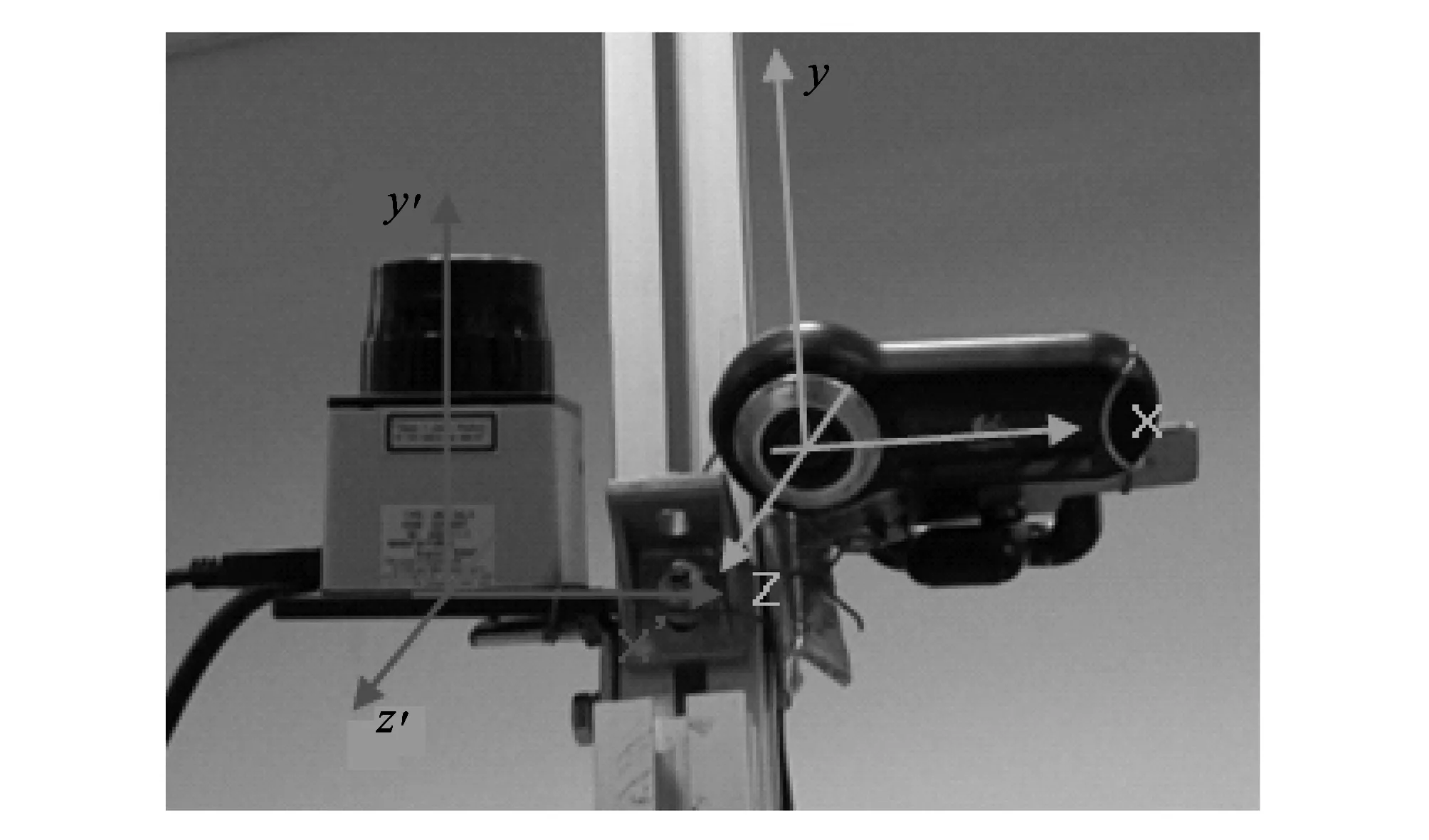
Fig.1 Sensor platform configuration
The goal of camera-laser calibration is to find out the relative pose between laser's coordinate system and camera's coordinate system, namely
(1)
(2)
In Eq.(1), this relative pose can be represented as a 3×3 rotation matrix φ and a translation vector Δ. With the mapping relationship defined in Eq.(1), for any laser point Plin laser's domain, it can be mapped onto a point Pcin the camera's coord inate system, and then onto a point Piin the image plane through camera intrinsic matrix K, as shown in Eq.(2).
For the calibration process, a method in Ref.[7] is used. In this method, the calibration is based on observing a planar chessboard pattern and solving for constraints between the views of the chessboard from camera and laser scanner. As shown in Fig.2, a planar chessboard is posed in both views of camera and the laser scanner. Assuming that the chessboard is the plane Zw=0 in the world coordinate system, then in the camera coordinate system, the chessboard plane can be parameterized by a vector N, which is parallel to the norm of the chessboard plane. The magnitude ‖N‖ equals to the distance from camera to the chessboard plane. By using pinhole camera projection model, it can be derived as
(3)
where r3is the third column of camera rotation matrix with respect to the chessboard and c is camera's center in world coordinate system. These can be obtained from camera's intrinsic and extrinsic parameters via Zhang's camera calibration method[8].

Fig.2 Camera-laser calibration using chessboard
As the laser points must lie on the chessboard estimated from camera, a geometric constraint between camera and laser's coordinate system can be obtained as

(4)
As N can be estimated from camera's extrinsic parameters with respect to the chessboard, and Plcan be obtained from laser's reading, for one laser point on the chessboard, one constraint on φ and Δ is given. By accumulating many laser points on chessboard in various locations and orientations, a best solution for φ and Δ can be estimated by solving Eq.(4) with standard linear least squares.
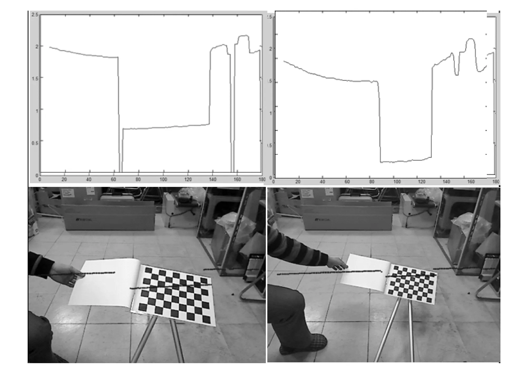
Fig.3 Mapping laser points onto image
After getting the solution for φ and Δ, a laser point can be mapped from laser's coordinate system to the image plane by using Eqs.(1) and (2). One such example is shown in Fig.3, where the blue dots show the position of laser points after mapping onto the image plane, with their corresponding distance readings shown in the graph on top.
2 Fusion model
By doing laser-camera calibration, a pixel-level fusion of laser and camera data can be achieved, which provides the foundation for the next feature-level fusion. For feature-level fusion, laser profiles in the laser domain and edge profiles in the image domain are extracted and associated in the form of a fusion profile model.
2.1 Laser data model
As the general shape of obstacles on the pedestrian path can be well approximated by polygons, a poly-line model is used to represent laser data in the laser domain. To fit laser data into poly-line model, the first step is to group all the measures of a scan into several clusters. A cluster is a set of laser points close enough to each other based on certain distance criterion. Here a distance criterion in Ref.[9] is used for clustering the laser data, one cluster is considered as from one specific object.
For each laser point cluster, a poly-line model is defined as
L={li=[Pi1,pi2,ai,bi]T, 0≤ilt;n},
(5)
where Pi1and Pi2are two terminal points of i-th line segment, aiand biare two parameters which define the i-th line segment.
A recursive line fitting algorithm is used to detect the break points on the set of points of the cluster.
The model fitting process starts by connecting two terminal points of the cluster with a straight line, and for all points between, the distances to the line are calculated. If the maximum of these distances, dmax, exceeds a given threshold, the line is split at this point, and this point is detected as a new break point. This process runs recursively until no more break points can be found.
2.2 Edge model
Edges in the image usually indicate the contour of objects. To represent edges in the image domain, a pixel-link model is used. Pixel-link is defined as a vector which contains 5 parameters lt;ID, P1, P2, L, αgt;, where ID is the label of this pixel-link, P1and P2are two terminal points, L are the length and α is the direction of this pixel-link[10].
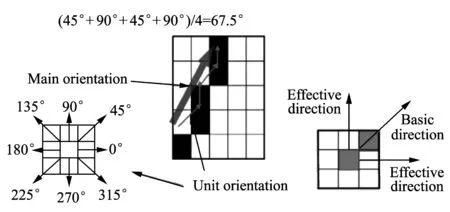
Fig.4 Pixel-link definition
2.3 Fusion of laser and edge
For fusion of laser data and edges in the image, the idea is illustrated in Fig.5.

Fig.5 Laser and edge fusion
Suppose there is a rectangular shape object in the scene, the red line indicates laser profile which is modeled in poly-line with three break-points. After laser profile is mapped onto the edge image, at each break-point's location, a square region is searched to find the starting pixel of a new pixel-link. When a starting pixel is found, edge-pixel tracing starts to trace all the edge-piels associated with the starting pixel. Basic unit-directions and effective unit-directions are used to guide the tracing.
The edge-pixel tracing process continues until one of the following two conditions are met:
1) No more connected edge-pixels can be found.
2) Unit-direction of next neighboring edge-pixel falls out of effective direction range.
In either case, current link will terminate and a new link will be initialized from the starting-pixel searching process until no more unlabeled edge-pixels can be found-the whole pixel-linking process terminates and a bunch of edge-links associated with this laser break-point can be extracted. To estimate a main orientation of all these associated edge-links, a voting scheme via orienuation histogram is proposed. The main orientation is determined by the bin with majority votes in the orientation histogram and a line segment with this main orientation is generated passing through the break point for the final representation of object's vertical profile.
3 Experimental results
In the experiment, a Hokuyo URG-04LX laser scanner and a Logitech 9000L webcam are used. These two sensors are laterally attached to a vertical bracket, as shown in Fig.1.
The first step is to cluster laser segment in laser's range data domain. Fig.6 shows laser clustering resumts. In Fig.6, laser sensor is located at (0,0), and different laser point segments are labelled in different colors. There are totally 13 segments are clustered using the clustering criterion defined in section 2. Some segments which contain very few laser points can be ignored. There are four major segments can be observed in Fig.6. Each major segment is supposed to be corresponding to one single object.
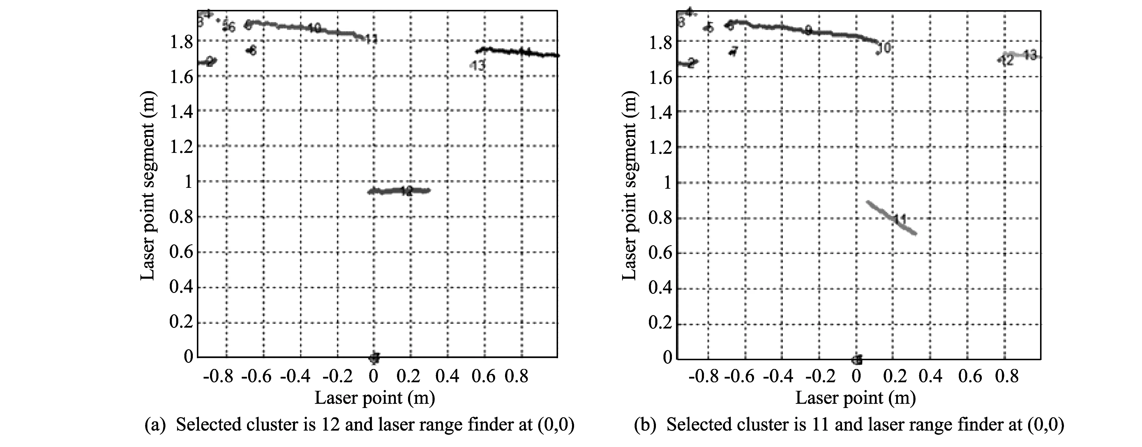
Fig.6 Laser segment clustering

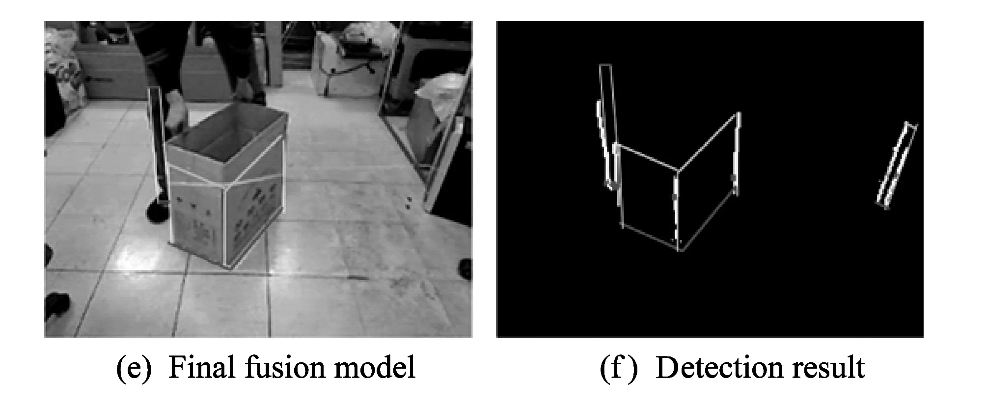
Fig.7 Laser and edge fusion
Fig.7 shows more results in the following steps. Fig.7(a) shows pixel-level fusion result of laser data and image. Laser segments are mapped onto the image, and the color of laser segments encodes the distance value at each laser point. Fig.7(c) shows these laser segments in the laser's range data domain. These laser segments are fitted into poly-line model with break points marked in green squares. Fig.7(b) shows edge map of the image with all the laser break points labelled. In the edge map, it is usually very difficult to identify objects just depending on their edges. However, laser segments projected on each object gives another very helpful clue for identification of objects. Thus, in Fig.7(d), by searching for edge links which is associated with the laser segments break point, edges which belong to each object can be easily extracted. Fig.7(f) shows the final fusion model fitted for each object in the detection range, and Fig.7(e) maps the fusion model to the original image to show the final detection result.
4 Conclusion
In this paper, an obstacle detection method by using laser and camera fusion is proposed. On one hand, laser can provide high-resolution range data and is capable of detecting ground-level objects like curbs, steps or drop-offs which are generally very difficult to detect using camera. On the other hand, camera can capture the whole scene at high frame rate, which does not require laser to actually scan the environment for collecting data of the whole object profile.
[1] Dakopoulos D, Bourbakis N G. Wearable obstacle avoidance electronic travel aids for sight-impaired: a survey. IEEE Transactions on Systems, Man, and Cybernetics, 2010, 40(1): 25-35.
[2] Rodriguez A, Bergasa L M, Alcantarilla P F, et al. Obstacle avoidance system for assisting visually impaired people. In: Proceedings of IEEE Intelligent Vehicles Symposium, Alcala de Henares, Spain, 2012: 34-39.
[3] Mora J L G, Hernandez R, Ramos L F R, et al. Research and development team in space perception using sounds with specific aplication for blind people. [2013-02-21]. http://www.iac.es/proyect/eavi.
[4] Dakopoulos D, Boddhu S K, Bourbakis N. A 2D vibration array as an assistive device for visually impaired. In: Proceedings of the 7th IEEE International Conference on Bioinformatics and Bioengineering, Chania, Greece, 2007: 930-937.
[5] Bourbakis N. Sensing 3D dynamic space for sight-impaired. IEEE Engineering in Medicine and Biology Magazine, 2008, 27(1): 49-55.
[6] Yuan D, Manduchi R. A tool for range sensing and environment discovery for the blind. In: Proceedings of Computer Vision and Pattern Recognition Workshop(CVPRW’04), Washington, USA, 2004: 39-41.
[7] ZHANG Qi-long, Pless R. Extrinsic calibration of a camera and laser range finder. In: Proceedings of IEEE/RSJ International Conference on Intelligence Robots and Systems(IROS), 2004: 2031-2036.
[8] ZHANG Zheng-you. A flexible new technique for camera calibration. IEEE Transactions on Pattern Analysis and Machine Intelligence, 2000, 22(11): 1330-1334.
[9] Dietmayer K C J, Sparbert J, Streller D. Model based object classification and object tracking in traffic scenes from range images. In: Proceedings of IEEE Intelligent Vehicles Symposium, 2001: 25-30.
[10] Lin Q, Han Y J, Hahn H S. Real-time lane departure detection based on extended edge-linking algorithm. In: Proceedings of the 2nd International Conference on Computer Research and Development, 2010: 725-730.
date: 2013-05-22
The MSIP(Ministry of Science, ICT & Future Planning), Korea, under the ITRC(Information Technology Research Center) support program (NIPA-2013-H0301-13-2006) supervised by the NIPA(National IT Industry Promotion Agency)
Youngjoon Han (young@ssu.ac.kr)
CLD number: TN911.74, TN249 Document code: A
1674-8042(2013)03-0247-05
10.3969/j.issn.1674-8042.2013.03.010
杂志排行

Journal of Measurement Science and Instrumentation的其它文章
- Impact of low temperature on smartphone battery consumption*
- Roll angle measurement system based oni triaxial magneto-resistive sensor*
- Dynamic test methods for natural frequency of footbridge*
- High-speed broadband data acquisition system based on FPGA*
- Method of military software security and vulnerability testing based on process mutation*
- Study on denoising filter of underwater vehicle using DWT*