CdS-ZnSe和CdSe-ZnS量子点的合成和Förster能量转移研究
2013-10-17弓亚琼张贺楠卫增岩
弓亚琼 詹 寰 张贺楠 卫增岩 苏 伟*,
(1中北大学化工与环境学院,太原 030051)
(2Department of Chemistry,City College of the City University of New York,New York,10031,USA)
(3Department of Chemistry,Hunter College of the City University of New York,New York,10065,USA)
0 Introduction
For over a decade,QDs have found applications in various areas from biological imaging,novel sensors to electroluminescence light-emitting diode (LED)due to their unique optical and electrical properties[1-4].For these applications,it is advantageous that QDs have broad absorption bands,size-dependantphotoluminescence(PL)property,high quantum yield(QY)and excellent chemical stability as compared to conventionalorganic dyesin addition to narrow emission peaks[5].Recently,among QDs,type II core-shell QDs such as CdS-ZnSe,ZnO-CdS and CdSe-CdTe have received significant attention due to their unique band alignment where the band structures of the core and the shell materials are staggered and one carrier is predominantly confined to the core and the other is located in the shell with photon excitation[6-7].This feature contrasts to the commonly studied typeⅠQDs where both carriers are confined in the same physical domain of type Ⅰ QD[8].For the type Ⅱ QDs,the recombination rate between the electron and the hole is diminished due to the reduced wavefunction overlap between the carriers and thus has longer exciton lifetime.
Frster resonance energy transfer(FRET)is a nonradiative energy transfermechanism between an excited donor fluorophore and a ground-state acceptor fluorophore through dipole-dipole interactions[9].Three important requirements for FRET to occur between donors and acceptors are: (i)The photon emission energy of donors has to be greater than that of acceptors, (ii)The donor emission band and the acceptor absorption spectra has sufficient overlap,and(iii)The distance between donors and acceptors is within the distance limit of FRET (~10 nm)[10-11].If all three requirements are met,the resonance energy transfer between donors and acceptors occurs in high probability and the FRET induces both PL intensity quenching and reduction of the carrier lifetime of the donor[10].
QDs were examined as donors in FRET-based studies to replace traditional fluorescent dyes in biological applications such as biological imaging,DNA detection,and cell tracking[12-14].The FRET-based sensor is a great example to take advantage of QDs as donors because the narrow emission band of QD donors does not interfere with the direct excitation of acceptors and thus detects only signals induced by FRET.This is extremely important in the design of bio-sensorssincetheemission band ofacceptor enhanced by FRET could be detected easily from large background PL bands.From the PL intensity change of acceptor in a bio-sensor system,one is able to examine the concentration of target biological molecules via antigen-antibody conjugation method[12].Driven by these important applications,the FRET mechanism between QDs and dye-labeled biomolecules has been investigated in a variety of solvents,temperatures,and pH values[5].Few studies have been reported on the FRET with type Ⅱ QDs.This is in part due to the difficulty in synthesizing typeⅡQDs,and the spatial separation of carriers of typeⅡQDs is a concern to lower quantum yields[15-17].However,the type Ⅱ QDs are still interesting acceptors since their long excitonic lifetime enhances the probability for the energy transfer to the acceptor before electrons and holes of the donor recombine.Despite this potential,there has been no report in our knowledge to explore typeⅡQD as acceptors in the FRET process.The aim of this report is to investigate the potential of the typeⅡQDs as an acceptor in QD-based FRET complexes.
In this work we assembled QD hybrid structures from typeⅠCdSe-ZnS QDs and typeⅡCdS-ZnSe QDsto study theirenergy transfermechanisms through time-resolved and steady-state photoluminescence (PL) measurements.These measurements reveal reduction of the donor lifetime,indicating the occurrence of FRET between typeⅠand typeⅡ QD.Experimental data support that the long-range resonance-energy transfer is sufficiently effective between QDs and the enhancement is larger as the exciton lifetime of donors is extended,as expected by Frster theory.
1 Experimental
The typeⅠCdSe-ZnS (QD491)and the typeⅡCdS-ZnSe (QD560)QDs reported here were prepared by using a stepwise procedure composed of:1)core nano-crystals growth (CdSe,CdS),2)shell overcoating (ZnS,ZnSe),3)tri-n-octylphosphine oxide(TOPO)/tri-n-octylphosphine (TOP)-capping,and 4)size selection precipitation and final purification[6,18-20].The diameter of QD cores and the shell thickness were necessary to be precisely controlled in the synthesis in order to optimize the spectral overlap between the emission bands of the donors and the absorption bands of the acceptors.
1.1 Instruments and Materials
1.1.1 Instruments
The steady-state fluorescence spectra were acquired using a spectrometer (Horiba Jobin-Yvon)with a Xenon lamp as an excitation source at 367 nm.The time-resolved fluorescence measurements were carried out using a time-correlated single photon counting(TCSPC)system(Horiba Jobin-Yvon)at room temperature.A 200 Pico series (PS)diode laser operating at 1 MHz repetition rate and 467 nm emission wavelength wasused asthe excitation source.The time-resolved data were deconvoluted by using the iterative nonlinear least squares method.Absorption spectra were recorded by a Cary 50 Probe UV-Vis spectrophotometer in the wavelength range of 400~700 nm.
Transmission Electron Microscopy(TEM)samples were prepared by attaching a carbon-coated copper TEM grid on a piece of 1.0 cm ×1.0 cm silicon substrate,applying spin-coating procedure to the same volume of QDs solution,then peeling the TEM grid off from the silicon substrate after baking it for 1 hour at 40℃.All TEM samples were studied by Zeiss EM 920 Transmission Electron Microscope at an acceleration voltage of 80 kV.
1.1.2 Materials
All chemicals were used without further purfication:trioctylphosphane (TOP) (97%;Sigma-Aldrich),Trioctylphosphane oxide (TOPO,99%;Sigma-Aldrich),hexadecylamine(HDA,98%;Sigma-Aldrich),dodecylphosphonic acid (97%;Sigma-Aldrich),methanol (Sigma-Aldrich),hexane(Sigma-Aldrich),bis (2,4,4-trimethylpentyl)phosphinic acid(BTMPPA,99%;Sigma-Aldrich),diethylzinc (95%;Sigma-Aldrich),hexamethyldisilthiane(>97%;Fluka),oleylamine (7 mL,98%),CdO,Se and S(Sigma-Aldrich),oleylamine(Sigma-Aldrich).
1.2 Synthesis of CdSe-ZnS typeⅠQD(QD491)
1.2.1 Synthesis of CdSe cores
First,51.4 mg (0.4 mmol)of CdO (Sigma-Aldrich)was placed into a flask containing 1.15 mL(1.045 g)of Trioctylphosphane oxide (TOPO,99%;Sigma-Aldrich)and then it was mixed with 2.85 mL(2.375 g)of hexadecylamine (HDA,98%;Sigma-Aldrich)at 270 ℃ under nitrogen flow.After 230 μL(0.8 mmol)of dodecylphosphonic acid was added and temperature of the resulting colorless solution was raised to 250 ℃,3.5 mL of a 0.2 mol·L-1solution of Se (Sigma-Aldrich) powderin trioctylphosphane(TOP) (97%;Sigma-Aldrich)was quickly injected.The reaction was stopped after 45 seconds by pouring the mixture into 30 mL methanol(Sigma-Aldrich)at room temperature.After the CdSe cores were purified by rinsing in methanol and centrifugation (14 000 r·min-1,15 min.),the resulting compounds were redispersed in hexane(Sigma-Aldrich).
1.2.2 Coating ZnS shell onto CdSe cores
First,14 g Trioctylphosphaneoxide (TOPO)(99%;Sigma-Aldrich),3 mL oleylamine(99%;Sigma-Aldrich),2 mL HDA (98%;Sigma-Aldrich),and 2.0 mmol bis (2,4,4-trimethylpentyl)phosphinic acid(BTMPPA,99%;Sigma-Aldrich)were degassed under vacuum for 2 hrs in a three-necked flask at 100℃.CdSe cores dispersed in hexane from previous synthesis were added to the degassed solution and the hexane was removed at 80℃ under vacuum.Under a flow of argon,the mixed solution was heated at 180°C and the ZnS shell precursor solution (0.1 mmol diethylzinc (95%;Sigma-Aldrich)and 0.1 mmol hexamethyldisilthiane (>97%;Fluka)dissolved in 7 mL TOP)was added dropwise.After the addition was complete,the solution was kept at 180℃for 5 min and then left stirring overnight at 75℃to anneal the ZnS shell.The resulting CdSe-ZnS core-shell QDs were purified by precipitation in methanol,same as the core-purification procedure.The final QDs were re-dispersed in hexane.
1.3 Synthesis of CdS/ZnSe typeⅡQDs(QD560)
1.3.1 Synthesis of CdS cores
The Cd precursor solution was prepared by mixing a degassed (under vacuum at 100℃for 1 h)solution ofcadmium acetate hydrate (1 mmol),trioctylphosphane (TOP)(6 mL),and bis(2,4,4-trimethylpentyl)phosphinic acid(BTMPPA)(1 mmol)with a degassed (under vacuum at room temperature for 1 h)solution of elemental sulfur(1 mmol,Sigma-Aldrich)in oleylamine (3 mL,Sigma-Aldrich).The resulting solution was rapidly injected into a roundbottomed flask containing degassed (under vacuum at 100℃for 1 h)oleylamine (7 mL,98%)and trioctylphosphane (TOP) (8 mL)stirring rapidly at 250~280℃.After QDs were grown at 250℃ for 15 to 30 min,the heating was stopped and cooled down by removing the heating source.Before coating the ZnSe shell,the CdS QD cores were precipitated out of the growth solution and then separated from hexane solution one more time to remove unreacted precursors and excess capping ligands.The resulting particles were flocculated from the growth solution by adding 0.4 mol of hexane,0.8 moles of butanol,and 3 moles of methanol (total 100 mL)to 1 mole of growth solution(24 mL)and centrifuged for 15 min at 14 000 r·min-1.These particles were dispersed in hexane and flocculated by adding one drop of butanol per mole of original growth solution and 0.5 mol of methanol,and then centrifuged for 15 min.The CdS core nanoparticles were finally re-dispersed in pure hexane.
1.3.2 Coating of ZnSe shell onto CdS cores
A colloidal solution of ca.20 mg of CdS QD cores was placed in a three-neck flask under purified argon flow.After adding 2.5 mL of TOPO with 1.5 mL of HDA,the mixture was heated at 190℃and then kept at this temperature to evaporate hexane completely.Zinc stearate (316 mg,98%;Sigma-Aldrich)was dissolved in 2.5 mL of toluene upon gentle heating (ca.60 ℃ ).After cooling to room temperature,the resulting 0.2 mol·L-1solution was mixed with 2.5 mL of a 0.2 mol·L-1solution of Se in TOP.This mixture was injected with a syringe pump within 1 hour into the reaction flask containing the CdS core nanocrystals at 190℃.Periodically small aliquots were removed in order to monitor the shell growth by TEM.After the addition was completed,the resultingcrystalswereannealedat190℃for additional 1 ~1.5 hours.The core-shell QDs were purified by the precipitation method same as the coreprocessing procedure.The final CdS-ZnSe type II QDs were re-dispersed in hexane.
1.4 Building of QDs Assembly Samples
1.4.1 Preparation of Solid QDs Assembly Samples
All QDs samples were casted by spin coating solution of QDs in hexane onto a 1.0 cm ×1.0 cm silicon substrate under ambient atmosphere.Following the spin coating,the samples were placed in an oven at 40℃for 1 hour to remove the trace amounts of organic solvents,before they were characterized by steady-state PL and time-resolved PL.The control samplesfor the typeⅠ QD491-typeⅡQD560 assembly consist of either only the donor of(QD491)CdSe-ZnS QDs or the acceptor of CdS-ZnSe(QD560)QDs.All control samples were prepared in exactly the same concentration as the one in the corresponding mixed QDs samples on silicon.The donor-to-acceptor stoichiometry ratio was varied in the mixed QDs samples by keeping the concentration of donor QDs constant and varying the concentration of acceptor QDs.
1.4.2 Concentration Calculation
The assembly of typeⅠQD491 donor-typeⅡQD560 acceptor with differentdonor-to-acceptor stoichiometry ratios were prepared and studied by using steady-state and time-resolved PL spectroscopy.The concentration of QDs solution was determined analytically from the total amount of Cd and the sizes of QDs.For example,for the QD491,the CdSe core was dried and weighed as 16.24 mg after synthesis.The number of CdSe QDs core is about 9.0 ×10¹⁶assuming each CdSe QDs weighs 1.8×10⁻¹⁹g estimated from the diameter of 1.95 nm and the density of 5.816 g·cm-3.After the CdSe core was coated by ZnS and finally redispered in 200 mL ofhexane,the concentration of QD491 solution is 7.5×10⁻⁷mol·L-1.
The assembly of QD491-QD560 QDs,the donorto-acceptor molar ratio of CdSe-ZnS(QD491)QDs and CdS-ZnSe (QD560)QDs was varied among 10∶1,5 ∶1 and 2 ∶1 while the concentration of CdS-ZnSe(QD560)QDs was varied among 3.6×1013cm-3(6.0×10⁻⁸mol· L-1),7.2×1013cm-3(1.2×10⁻⁷mol·L-1)and 1.8×1014cm-3(3.0×10⁻⁷mol·L-1)and the concentration of CdSe-ZnS(QD491)QDs was maintained as constant of 3.6×1014cm-3(6.0×10⁻⁷mol·L-1).
2 Results and Discussion
The band alignment of typeⅠQD491 donortypeⅡ QD560 acceptor assembly is shown in Fig.1(a).For this QDs assembly,as the energy is transferred from typeⅠCdSe-ZnS (QD491)QDs to the core of typeⅡCdS-ZnSe(QD560)QDs,the excited electrons and holes relax to the ground state of the conduction band in CdS and the valence band in ZnSe,respectively,according to the typeⅡband alignment,resulting in the typeⅡ emission.
To confirm the band overlaps between this donoracceptor QDs pair,emission bands for donors and absorption bands for acceptors are compared as shown in Fig.1 (b).This spectral comparison shows the significant overlap between the PL emission of typeⅠQD491 and the lowest-energy absorption band of typeⅡ QD560 as shown.The small Stokes shift,~0.05 eV,of the PL emission of acceptor QD560 with respect to their lowest-energy absorption peaks indicates that these QDs have very few surface defects and have well-passivated surfaces[6].

The QDs assembly system,typeⅠdonor QD491 typeⅡacceptor QD560,was also examined for the comparison with the result from the typeⅡdonor typeⅠ acceptor system.A series of solid samples were studied by varying the concentration of QD560 in the fixed concentration of QD491 in the QDs-QDs FRET assembly.It is worth noting that for the type ⅠQDs-typeⅡQDs assembly,the FRET is expected to be less discernible because the decay time of donor is shorter than that of acceptor due to the fast electronhole recombination of the type Ⅰ QDs donor.Hence three different mixed solid samples were prepared from CdSe-ZnS(QD491)QDs and CdS-ZnSe(QD560)QDs at the donor-to-acceptor molar ratios of 10∶1,5∶1 and 2∶1.To achieve these ratios,the concentration of CdS-ZnSe(QD560)QDs was adjusted among 3.6×1013cm-3(6.0×10⁻⁸mol·L-1),7.2×1013cm-3(1.2×10⁻⁷mol·L-1)and 1.8×1014cm-3(3.0×10⁻⁷mol·L-1)and then they were mixed with CdSe-ZnS (QD491)QDs at the constant concentration of 3.6×1014cm-3(6.0×10⁻⁷mol·L-1).The Gaussian function-fitted spectra can be deconvoluted into neat QD491 and QD560 PL peaks for all of three mixed solid samples.The quenching of type Ⅰ donor QD491 is observed in Fig.2(a)as compared with the PL spectra of neat QD491 at the same concentration.PL intensity ofQD491 is gradually decreased as the concentration of QD560 is increased in this typeⅠdonor QDs-typeⅡacceptor assembly.
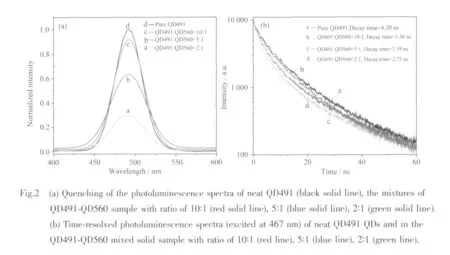
To calculate the quenching efficiency of the typeⅠ donor QD491 in this QDs assembly,Eq.(1):Q=(IFree-IMix)/IFree,is used,where IFreeand IMixare the integrated PL intensities of the neat QD491 in the solid state sample and the PL intensity of the QD491-QD560 mixed solid sample,respectively,under the same QD491 concentration[21].From these spectra,the Q value is 4.1%,13.1%and 62.6%,for the donor-toacceptor ratios of 10∶1,5∶1 and 2∶1.The increasing Q value shows its dependence on n (the number of acceptor QD560 per donor QD491),which indicates that the FRET efficiency is enhanced by increasing the number of the acceptor of QD560 around the donor of QD491[23].This is because the number of acceptors perdonoraffectsthe FRET efficiency according to the following Eq.(2):Eff=nR06/(nR06+r6),where Eff is FRET efficiency,n is the number of acceptors per donor,R0is Frster distance,and r is donor-acceptor distance[5].Increasing n yields higher FRET efficiency when R0and r are fixed in this case.
Time-resolved PL measurements were also carried out on all mixed samples and neat QD491 sample for the binary QDs assembly of the typeⅠdonor QD491 and the typeⅡacceptor QD560 QDs.The time-resolved PL spectra of these samples are shown in Fig.2(b).From the plot,the neat QD491 has a PL lifetime of 4.20 ns.The PL lifetime decreases to 3.38 ns,3.19ns and finally reaches 2.75 ns as the QD491-QD560 ratio is changed to 10∶1,5∶1 and 2∶1.This trend indicates that the quenching of typeⅠdonor QD491 is caused by FRET between QD491 and QD560[16].The energy transfer efficiency from QD491 to QD560 is determined by the same Eq.(3)as fellows:τmix.-1=τfree-1+ΓFRET,where τmixand τfreeare the lifetime of the QD491 in the mixed samples and the lifetime of the neat QDs,respectively[17].The energy transfer efficiency for each sample is estimated by Eq.(3)to be 5.78%,7.55%and 12.56%as the QD491-QD560 ratios are changed among 10 ∶1,5 ∶1 and 2 ∶1,respectively.This trend is consistent with the change in Q values on the same series of samples.
When the typeⅠQDs are excited both electrons and holes are confined in the cores.However,in the case of the typeⅡQDs,one carrier is confined in the core while the other is confined in the shell.Because the spatial separation of carriers in the typeⅡQDs reduces the recombination of carriers,the typeⅡQDs have longer PL lifetime than the typeⅠQDs.In the first QDs assembly,the donor of the typeⅡQD560 QDs is still in the excited state when the energy transfer is initiated due to the longer lifetime of the type Ⅱ donor QDs.In the case of the second QDs assembly,the donor of the typeⅠQD491 relaxes faster than the acceptor of typeⅡQD560 to recombine two carriers,and thus the typeⅠdonor QD491 is inefficient in the FRET process.This is why the typeⅠQDs have not been employed as acceptors in FRET assemblies,and even less FRET studies have been done using the type Ⅱ QDs as acceptors.
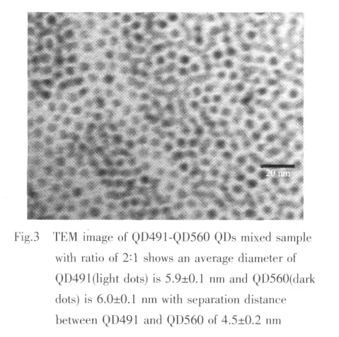
To measure the inter-particle distance between typeⅠand typeⅡQDs in the QDs assemblies,transmission electron microscopy (TEM)analysis of each QDs assembly was conducted.The QD491 typeⅠQDs consist of CdSe cores with outer diameter of(3.9 ±0.1)nm,determined by TEM.The CdSe cores were over-coated by ZnS shell with a thickness of~1 nm.The CdS-ZnSe (QD560)typeⅡ QDs consist of CdS core with a diameter of 4.0±0.1 nm and the ZnSe shell with a thickness of~1 nm.For all QDs in this report,TOPO and TOP were used as ligands to passivate surfaces of core-shell QDs.In Fig.3 both QD491 and QD560 QDs in the mixed sample are close packed,forming a glassy solid on the TEM grid where each QDs remains separated from its neighbors by the organic capping groups.The separation between adjacent QDs is about(4.5±0.2)nm for the second QDs assembly.Combining this result and the spectroscopic observation,it is evident that QD491-QD560 separation distance (4.5±0.2)nm are within the FRET distance in the solid state samples prepared by spinning coating.
It is also possible that the emission is quenched by the aggregation of acceptor QDs,but this is not the case in our observation[23-24].If the aggregation of QDs is the main reason for the PL quenching,all of the QDs samples in the assembly should show the same quenching efficiency.However,both the PL and TRPL spectra clearly show that the quenching efficiencies are dependent on donor-to-acceptor ratios.Especially for the QD491,the PL intensity is dramatically quenched (62.6%)in the presence of QD560 in the mixed sample,and the FRET efficiencies increase gradually as the percentage of QD560 is increased.Therefore,aggregation ofQDsisnotthemajor pathway for the PL quenching in these experiments.
3 Conclusions
In this report, we have synthesized and assembled solid state samples from the combinations of two QDs:CdSe-ZnS (QD491)typeⅠQDs(donor)and CdS-ZnSe(QD560)typeⅡQDs(acceptor)with various mixing ratios.The FRET process between these donors and acceptors in the QDs assemblies is confirmed by the PL intensity quenching and the decreased PL lifetime of donor QDs in this assembly.Besides,it is worth noting that the energy gap between the donor QDs and the acceptor QDs on the basis of PL spectra, ~0.3 eV,is larger than their Stokes shift, ~0.05 eV,in the band gap diagram in Fig.1(b).Since the emission bands of the donor and the acceptor are more separated,this feature is especially advantageous for the accurate measurements of PL lifetimes due to the elimination of the interference of donor emission spectra from the FRET-driven acceptor emission spectra.
[1]Alivisatos A P.Science,1996,271:933-937
[2]Zhag J,Campbell R E,Ting A Y,et al.Nature Rev.Mol.Cell Biol.,2002,3(12):906-18
[3]Achermann M,Petruska M A,Kos S,et al.Nature,2004,429:642-646
[4]Lu S,Madhukar A.Nano Lett.,2007,7:3443-3451
[5]Medintz IL,Uyeda H T,Goldman E R,et al.Nature Materials,2005,4:435-446
[6]Ivanov S A,Piryatinski A,Nanda J,et al.J.Am.Chem.Soc.,2007,129(38):11708-11719
[7]Xu F,Volkov V,Zhu Y,et al.J.Phys.Chem.C,2009,113(45):19419-19423
[8]Kim S,Fisher B,Eisier H J,et al.J.Am.Soc.,2003,125(38):11466-11467
[9]Lakowicz J R.Principles of Fluorescence of Spectroscopy,2nded.,New York:Kluwer Academic/Plenum,1999:368-370
[10]Crooker S A,Hollingsworth J A,Tretiak S,et al.Phys.Rev.Lett.,2002,89:186802-1-186802-4(doi:10.1103/PhysRevLett.89.186802)
[11]Henglein A.Chem.Rev.,1989,89(8):1861-1873
[12]Medintz I L,Berti L,Pons T,et al.Nano Lett.,2007,7(6):1741-1748
[13]Sukhanova A,Devy J,Venteo L,et al.Anal.Biochem.,2004,324(1):60-67
[14]Wu X,Liu H,Liu J,et al.Nat.Biotechnol.,2003,21(1):41-46
[15]Wargnier R,Baranov A V,Maslov V G,et al.Nano Lett.,2004,4(3):451-457
[16]Wang C,Chen C,Wei C,et al.J.Phys.Chem.C,2009,113:15548-15552
[17]Wang C H,Chen C W,Chen Y T,et al.Appl.Phys.Lett.,2010,96:071906.doi:10.1063/1.3315876.
[18]Murray C B,Norris D J,Bawendi M G.J.Am.Chem.Soc.,1993,115(19):8706-8715
[19]Somers R C,Bawendi M G,Nocera D G.Chem.Soc.Rev.,2007,36:579-591
[20]Hines M A,Sionnest P G.J.Phys.Chem.,1996,100:468-471
[21]Jin L,Li S,Kwon B,et al.J.Appl.Phys.,2011,109:124310doi:10.1063/1.3597635(7pages).
[22]Weller H.Angew.Chem.Int.Ed.,1993,32:41-53
[23]Noh M,Kim T,Lee H,et al.Colloids&Surfaces A:Physicochem.Eng.Aspects,2010,359:39-44
[24]Zhang Y,Mi L,Wang P N,et al.J.Lumin.,2008,128:1948-1951
