The CFD Numerical Simulation on Ventilation of Indoor Transformer Substation
2013-06-02XULuwenWANGGuochaoDINGJunCHENSong
XU Luwen ,WANG Guochao,DING Jun,CHEN Song
1.Electric Power Science and Research Institute,Chongqing Electric Power Corporation,Chongqing 401123,China;2.School of Mechanical Engineering,Chongqing University of Technology,Chongqing 400054,China
1.Introduction
The rapid development of the Chinese economy,the rapid expansion of power grids,and the use of high voltage in urban areas have increased the requirement for city-network substations and for the more distribution points of transformer substation[1].The city-network electric-power substation in downtown bears a large electric power supply for the neighbor residents.In order to improve the efficiency of use of land,coordinate with the construction style of city buildings,and reduce the influence of the noise of the electric power substation on the urban environment necessitate,the application of a whole indoor layout substation has so far been spread out in designing city-network power substations[2-3].
The most significant difference between a citynetwork electric-power substation with a whole indoor layout and a traditionally designed electric-power substation is that equipment in the former,including the main transformer,is installed inside the station.Installing power transformers with high voltage and high capacity indoors reduces the heat they emit and ventilates them if they yield the same rated output as those in the outdoor layout[4-6].Therefore,avoiding substantial heat generation by normal loss during the operation of a transformer(as in the outdoor layout)through the natural(rather than forced)ventilation of the transformer room to ensure the normal operation of the transformer is a major function of the indoor city-network power substation.
This article describes the fluid flow and heat transfer of the natural ventilation of an indoor transformer,examines the heat dissipation of the indoor transformer as well as the mutual relation between the transformer structure and the area and location of the air inlet and outlet of the transformer room and the height of the transformer room,and proposes requirements for indoor transformer rooms for building and ventilation professionals.Traditional reconstruction entails high cost and possibly unsatisfactory outcomes.Numerical simulation by FLUENT not only reduces cost but also achieves high accuracy and is thus an excellent approach to reconstruction.
2.Numerical simulation
The geometry model of indoor substation with a main transformer is created in 3D software,as illustrated in Fig.1.It shows the layouts of the original air inlet and outlet of the transformer substation according to an actual indoor substation,with two inlets and two outlets located at the bottom and on the top of substation,respectively.
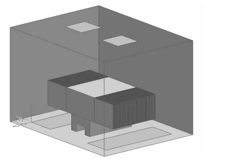
Fig.1 The geometry model of indoor transformer substation
The tool of MESHING in ANSYS software is used for meshing the model of indoor substation with the element type of tetrahedral grids employed to discrete the numerical model and the number of grids more than 2.5 million.The steady-state simulation scheme and integral separation algorithm are employed to numerically calculate the temperature distribution for a better convergence.The boundary conditions for inlets are prescribed as the type of velocity and for outlets as the type of flux[7].The CFD simulation is performed in FLUENT software,and then transferred in special software CFD-Post for postprocess[8].The analysis for the results of CFD of indoor substation focuses on the temperature distribution on the main transformer since the temperature on transformer or in room is a key factor to evaluate the efficiency of heat exchange in indoor substation.
3.Results and discussion
Fog.2 shows the contour map for temperature on the main transformer in indoor substation.It demonstrates that the higher temperature centers on the main transformer and that the values for temperature around in substation are far smaller than that of temperature.The partial maximum temperature of the main body of the original transformer reaches about 361 K or 88℃.
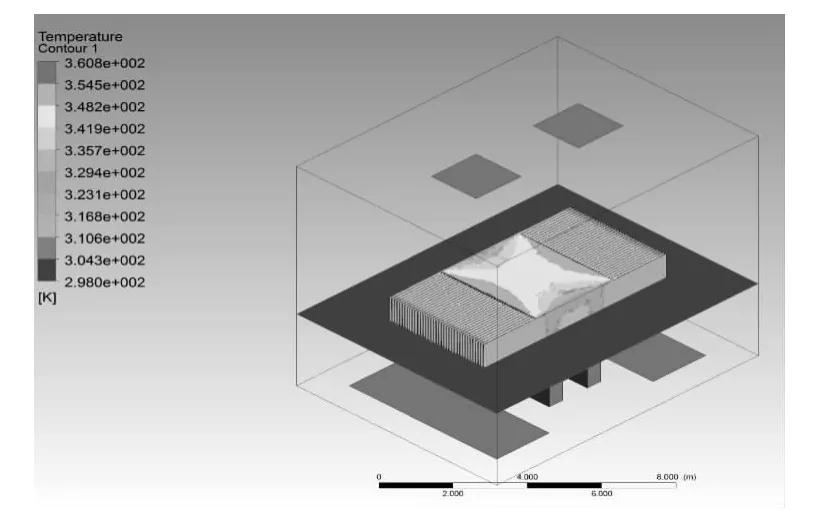
Fig.2 The temperature distribution on the main transformer
3.1.The optimization for distribution of inlets
The above conclusion suggests two optimum heat dissipation methods.With a constant area of the air inlet,varying the number and layout position of the inlet achieves the desired ventilation effect.The modified positions for two inlets are illustrated as Fig.3.The first dissipation method divides the original inlet into four pieces,with the total inlet area unchanged.These pieces are placed on the four corners of the main transformer room.The second dissipation method divides the original inlet into eight inlets of the same area and shape.These inlets are installed on the walls of the transformer room near the ground.
Employing the numerical scheme mentioned above,the numerical simulation for two various cases for inlets have been conducted and the results for temperature distribution on the main transformer are demonstrated in Fig.4(a)and(b).It shows the maximum temperatures of the main transformer according to numerical simulation are 627 K(354℃)and 357 K(84℃).The ventilation effect of the first dissipation method does not reach the heat dissipation requirement of the transformer.The ventilation effect of the second method is more significant than that of the first and stronger than that in the original layout.However,the actual air inlet in the project is difficult to install,extremely noisy,and very costly.Therefore,the new air inlet must be improved based on the advantages of the original,i.e.as Fig.1.
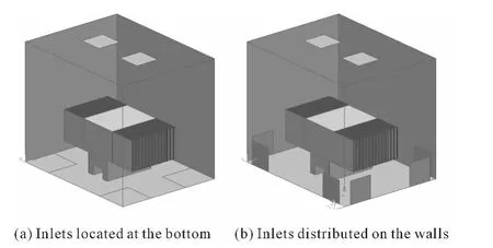
Fig.3 The various positions for inlets in indoor substation
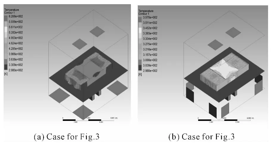
Fig.4 The temperature distribution on transformer for various inlets distribution
Based on the foregoing,the position and shape of the air inlet are changed and the cooling effect is optimized,with minimum cost.The three other optimization scenarios are as follows as Fig.5.For simplicity,we do not geometrically show the specific configuration for other three locations of inlets.Fig.5(a)shows the air inlet of the transformer substation is placed under the cooling fin of the main transformer,with the size and position of the air outlet unchanged.In this case,the maximum temperature of the main transformer is calculated as 355 K(about 82℃).Fig.5(b)shows a partial area from the side is added to the underside of the right head of the main transformer,with the total area of the air outlet unchanged.In this case,the maximum temperature of the main transformer is calculated as 355 K(about 83℃).Fig.5(c)illustrates the area of the air inlet below the right head of the main transformer is continuously increased,with the total area of the air outlet unchanged.The maximum temperature of the main transformer is calculated as 360 K(about 87℃).Heat dissipation in this scenario is not as satisfactory as in the above two scenarios.
It can be concluded that the heat dissipation of the cooling fin should primarily be considered in the ventilation design of transformer substations because it significantly affects the total heat dissipation of the transformer.Considering costs,layout difficulty,and all other factors,the location for Fig.5(a)is the optimal layout for substation air inlets.These inlets should be enhanced according to these findings.
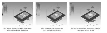
Fig.5 The temperature distribution on main transformer for three different positions of inlets
3.2.The optimization for distribution of outlets
For the sake of searching for a better solution to ventilation and heat transfer generated by the main transformer,other attempt is transferred to change the distribution of outlets.We considered two cases with the area for outlets of two cases unchanged.One is that the two air outlets are placed on the top right side of the cooling fin,while the other is that on the top right side of the transformer room.Fig.6(a)and(b)illustrates the temperature distribution on the main transformer for the case of outlets on the right side of the cooling fin and for the case of outlets on the top right side of the transformer room,respectively.
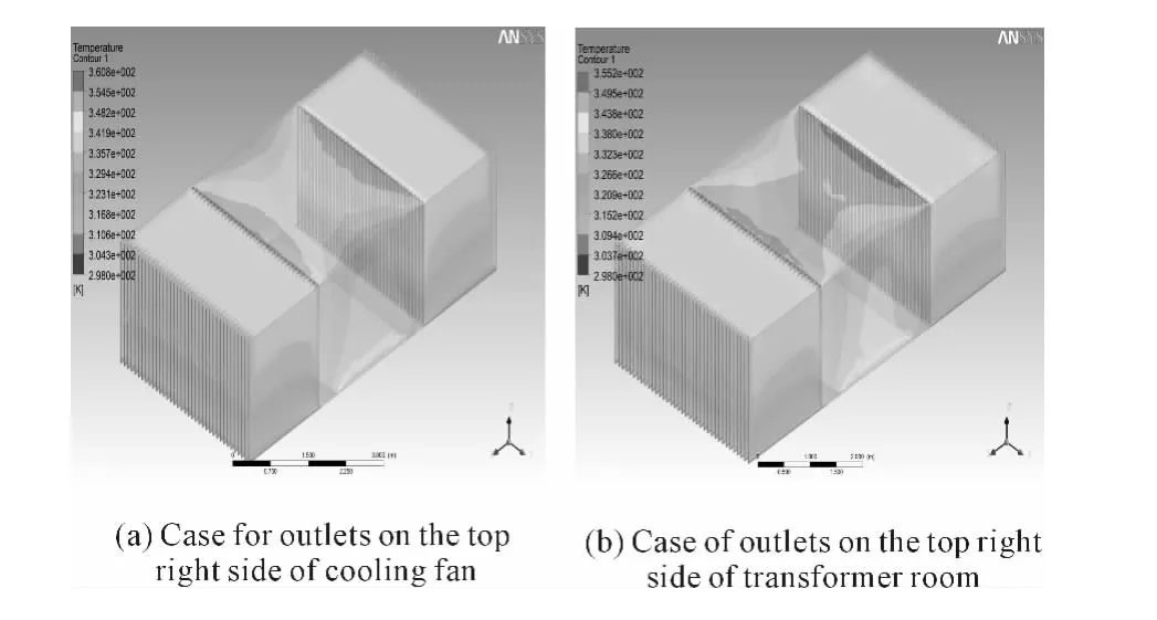
Fig.6 The temperature distribution on the main transformer
It shows the maximum temperature on the main transformer is reduced from 361 K(on the right top side of cooling fin)to 355 K(on the top right side of room),i.e.,from 88℃ to 82℃,a difference of 6℃.The optimized flow field more significantly enhances the heat dissipation of the transformer than the flow field before optimization.The layout of the new air inlet and outlet substantially facilitates airflow and the heat dissipation of the transformer and provides a reference for optimum transformer design.
4.Conclusions
The CFD simulations on ventilation and heat dissipation of indoor substation have been performed to improve the efficiency of heat exchange and find the optimum location for inlets and outlets.It can be concluded that the best inlets should be located at the right bottom side of the cooling fin,not of main transformer,and that the better location for outlets be on the right top side of the cooling fin,not the center of the transformer room.
[1]SONG Fuxiang,RUAN Lidong,SUN Quanhong.Affection and assessment of the environment around the transformer station[J].Safety and EMC,2005(2):90-92.
[2]XU Luwen,LI Yongming,LIU Changsheng.Analysis on power frequency electric and magnetic fields within 500KV substations in chongqing Area[J].Power System Technology,2008,32(2):66-70.
[3]YANG Min,ZHONG Haoping,YAN Qing.et al.Simulation and analysis of sound field in 220 KV urban indoor substations[J].Journal of Southeast University,2010,40(6):1226-1231.
[4]CHEN Qiu,LI Zhenhai.Research on noise control scheme of electric transformer substation[J].Electric Power Environmental Protection,2006,22(3):49-51.
[5]WANG Rongjie,CHEN Hongwei.Establishing and analysis of the noise model in the ventilation room[J].Journal of Huaqiao University:Natural Science,2008,29(1):14-16.
[6]JIN Lijun.Analysis on convection exchange in transformer Room[J].Electric Power Construction,2000,8:19-22.
[7]ANSYS Inc,Fluent User’s Guide,Cavendish Court,Lebanon,NH 03766,2010[S].
[8]ANSYS Inc,CFD-Post User’s Guide,Cavendish Court,Lebanon,NH 03766,2010[S].
杂志排行
机床与液压的其它文章
- Strength Analysis and Optimization of a Torsion Beam Rear Suspension
- Development of Vibration Signal Acquisition and Analysis System for Machine Tools Based on LabVIEW
- Numerical Analysis and Experimental Research on Micro Milling Process with Cycloidal Tool Path
- Analysis of the Optimization of Gear Pump Pulsation Based on Matlab
- Simulation Evaluation and Performance Analysis of a Double Coil Magnetorheological Valve
- Remote Condition-based Maintenance Approach to Hydraulic System of Construction Machinery