Numerical Analysis and Experimental Research on Micro Milling Process with Cycloidal Tool Path
2013-06-02CAOZiyangXUEXiaohongLIHua
CAO Ziyang,XUE Xiaohong,LI Hua
College of Mechanical Engineering,Suzhou University of Science and Technology,Suzhou 215009,China
1.Introduction
There is a strong demand from various industries for miniature devices and components with complex micro scale features fabricated on a variety of materials.Micro milling can overcome the limitations of semi-conductor based processing techniques by utilizing miniature tools to make complex 3D parts from different engineering materials with no need for expensive masks[1-2].How to set cutting conditions is very important,due to the fragile nature of the miniature tools。A minute vibration in micro end milling can lead to part failures.When cutting conditions are not appropriate,tools are easily fractured,which wastes time and money[3-4].In addition,in micro milling process,cutting forces and the tool displacements play an important role in the determination of the characteristics of cutting processes like tool wear and surface texture,the establishment of cutting plans,and the setting of cutting conditions[5-7].It is very important to study the dynamics of cutting forces and displacements in any machining process for proper planning and control of machining process and for the optimization of the cutting conditions to minimize production costs and cycle.
Micro milling process with circular tool path has been studied deeply,but the research about cycloidal cutter teeth motion is not perfect.Therefore,the cycloidal motion of the cutter teeth is modeled in this paper,rather than assuming a circular tool path.The numerical analysis includes the contribution of the tool vibrations to the instantaneous chip thickness and provides predictions for both force and deflection in the feed and normal directions.
The stability lobe diagrams that identify stable and unstable combinations of spindle speed and axial depth of cut is shown in a graphical format.This is followed by a detailed time-domain simulation predic-ting forces and displacements at stable and unstable machining region,and the variation in surface location error with axial location is estimated to improve the part geometric accuracy.
2.Modeling of micro milling with cycloidal tool path
Fig.1 Schematic diagram of cycloidal tool path
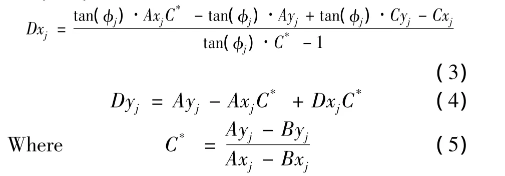
In order to calculate the instantaneous chip thickness at each time step,the(Cxj,Cyj)coordinates of the current tooth is compared to the surface coordinates recorded during the prior tooth passage at the same angular orientation.However,because the circular tool path assumption is not applied,it is not required that a data point exist at this angle from the prior pass.Therefore,a search must be completed to determine the two points from the previous tooth passage which bound this angle;these points are referred asAandBin Fig.1.Then linear interpolation between pointAand pointBis carried out to determine pointD,which lies on the line between pointCand the cutter origin.The coordinates of pointD,(Dxj,Dyj),are given in Eq(3)and Eq(4):
Then,it can be seen from Fig.1,the instantaneous chip thicknesshjcan be formulated as:
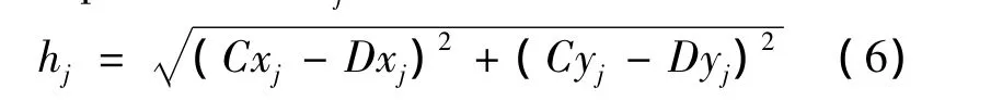
In any case that the chip thickness is greater than zero,the tangential and normal force components for toothj,Ft,jandFn,jis calculated by Eq.7 and Eq.8.

WhereFn,jandFt,jis normal and tangential cutting force,ktis the cutting coefficient in the tangential direction,knis the cutting coefficient in the normal direction,bis cutting width.As we’ll see,the cutting force expression is complicated by the chip thickness variation with cutter angle,the number of teeth simultaneously engaged in the cut at any instant.To describe these forces analytically,we must project the normal and tangential components into thexandydirections.
WhereFx,jandFy,jis the cutting force inxandydirection.Once the chip thickness is computed,the tangential component of the force in the current time step is determined.The normal force is then computed and these results are projected into thexandydirections.
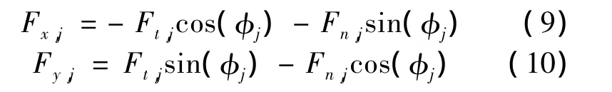
In the case of a helical cutting edge,the tool is segmented into multiple slices along its axis.We sum the forces for all slices to determine the total normal and tangential cutting force components for that particular simulation time step(and cutter angular orientation).The Eq(9)and Eq(10)are applied to pro-ject the forces onto thexandydirections,sum the forces over all the teeth engaged in the cut,and complete the numerical integration.
Then thexandydirection forces over all teeth engaged in the cut is summed at the given instant in time,these force values are used to determine the instantaneous displacementsxtoolandytoolfor the next time step by numerical integration of the modal equations of motion with the appropriate modal parameters.If multiple vibration modes are included,the displacementcontributions from each mode are summed to determine the total displacement.Multiple degrees of freedom in each direction can be accommodated by summing the individual modal contributions.
3.Results and discussion
The numerical simulations were completed with the following conditions:50%radial immersion milling,thexandydirection dynamics of machining system are symmetric withfn=550 Hz,k=1.8×10⁶N/m,and ζ=0.02.An aluminum alloy is machined with a four tooth square end mill with a helix angle of 30 degree and the cutting force coefficients arekt=1 650 N/mm2andkn=980 N/mm2.Wherefnis natural frequency,kis stiffness,ζ is damping ratio.These values are typically obtained from impact tests followed by a modal fitting procedure.
The stability lobe diagram with the spindle speeds from 3 000 rpm to 10 000 rpm is given in Fig.2,which is obtained by the frequency-domain method developed in our previous study[9].
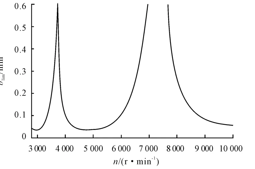
Fig.2 Stability lobe diagram for radial immersion milling
It can be seen from Fig.2 that it is stable below the lobe,and unstable above the lobe.In order to demonstrate the capabilities of the cycloidal tool path time-domain simulation,two different cases from the Fig.2 are considered:①n=6 000 r/min andb=0.4 mm.②n=7 500 r/min andb=0.4 mm.It can be seen from Fig.2 that the two cases are located at unstable and stable machining region,respectively.
Fig.3 shows theydirection forces and displacements for case 1.
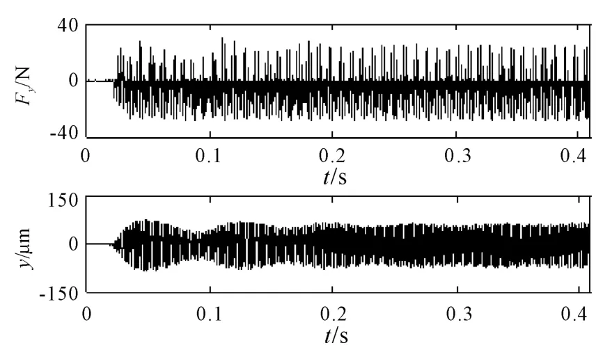
Fig.3 Simulation results for y direction force and displacement(n=6 000 rpm and b=0.4 mm)
As expected,the cut is strongly unstable for case 1.It can be seen from Fig.3 that the maximum forces are up to 40 N and the tool deflection increases to about 150 μm instantaneously,which may result in a poor surface finish and reduce the longevity of the tool in the actual milling process.
Theydirection result for case 2 is shown in Fig.4.
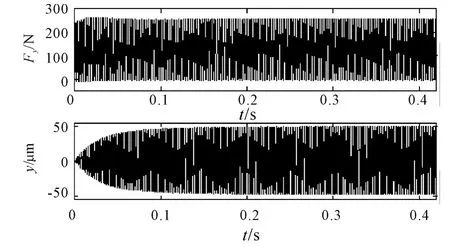
Fig.4 Simulation results for y direction force and displacement(n=7 500 r/min and b=0.4 mm)
As shown in Fig.4,case 2 provides stable operating conditions.The expected constant force and displacement for a four tooth cutter in 50%radial immersion milling is obtained.
In addition to the time plots,thexversusytool path is displayed in Fig.5 using the numerical simulation method.
Fig.5 presents the results forn=7 500 rpm,50%radial immersion up milling cut withb=0.4 mm at the tool point,i.e.,the axial slice nearest the free end of the tool.Only the portion of the tool path where the teeth enter the material is included.The tool center is nominally located aty=0,while thexposition varies with the time dependent feed.We can see that the top of the path is initially at the tool radius of 0.5 mm(nearx=0).After the entry transients,theydisplacement approaches 0.6mm at the path apex where the machined surface is located.This indicates an overcut condition because more material isremoved than commanded forthe up milling cut.
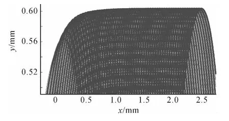
Fig.5 The x versus y tool path(n=7 500 r/min and b=0.4 mm)
The benefit of this figure is that it can be used to isolate the machined surface,which defines the machined surface geometry and the surface location error.The surface location error is determined by comparing theycoordinate of the mean of this line to the milling tool radius.For the up milling case shown in Fig.5,the surface location error is determined to be 100 μm.Therefore,more material is removed than commanded and an overcut surface is obtained.
Once the surface location error has been determined for all axial slices,the change in error with axial depth can be interrogated as shown in Fig.6.

Fig.6 Variation in surface location error with axial location(b varies from 0 to 0.4 mm)
It can be seen from Fig.6 the time-domain simulation results(dots)are superimposed on the frequency-domain solution(line)for the conditions described in previous simulation experiments.Fig.6 also indicates that the time-domain simulation results show a good agreement with the frequency-domain solution results.
4.Conclusions
This study presented frequency-domain solution to construct stability lobe and time-simulation method for predicting the force and displacement on the developed dynamics model of micro milling process with cycloidal tool path.It took into account the instantaneous cutting thickness,dynamic cutting force and tool displacement,and constructs the relevant equations.In addition,the variation in surface location error with axial location is estimated and the time-domain simulation results show a good agreement with t frequency-domain solution results.
[1]Quintana G,Ciurana J.Chatter in machining processes:A review[J].International Journal of Machine Tools and Manufacture,2011,51:363-376.
[2]Park S S,Malekian M.Mechanistic modeling and accurate measurement of micro end milling forces[J].Annals of the CIRP,2009,58:49-52.
[3]Altintas Y,Eynian M,Onozuka H.Identification of dynamic cutting force coefficients and chatter stability with process damping[J].Annals of the CIRP,2008,57:371-374.
[4]Salahshoor M,Ahmadian H.Continuous model for analytical prediction of chatter in milling[J].International Journal of Machine Tools and Manufacture,2009,49:1136-1143.
[5]Altintas Y,Stepan G,et al.Chatter stability of milling in frequency and discrete time domain[J].Annals of the CIRP,2008,57(1):35-44.
[6]Campomanes M L,Altintas Y.An improved time domain simulation for dynamic milling at small radial immersions[J].Journal of Manufacturing Science and Engineering,2003,125:416-422.
[7]Schmitz T,Couey J.Runout effects in milling:surface finish,surface location error,and stability[J].International Journal of Machine Tools and Manufacture,2007,47:841-851.
[8]Schmitz T,Mann B.Closed form solutions for surface location error in milling[J].International Journal of Machine Tools and Manufacture,2006,46:1369-1377.
[9]Ziyang Cao,H.Li.Research on regenerative chatter in micro milling Process[J].Hydromechatronics Engineering,2012,40:17-20.
杂志排行

机床与液压的其它文章
- Selection of Working Parameter for Bladder-type Accumulators with Different Conditions
- Development of Vibration Signal Acquisition and Analysis System for Machine Tools Based on LabVIEW
- Strength Analysis and Optimization of a Torsion Beam Rear Suspension
- Analysis of the Optimization of Gear Pump Pulsation Based on Matlab
- Simulation Evaluation and Performance Analysis of a Double Coil Magnetorheological Valve
- Remote Condition-based Maintenance Approach to Hydraulic System of Construction Machinery