Design of the A/D Converting Circuit for The Linear Time Grating Sensor
2013-06-02ZHANGTianhengLINGXu
ZHANG Tianheng ,LING Xu
a.Engineering Research Center of Mechanical Testing Technology and Equipment,Ministry of Education Chongqing Key Laboratory of Time Grating Sensing and Advanced Testing Technology;b.China College of Mechanical Engineering,Chongqing University of Technology,Chongqing 400054,China
1.Introduction
Position measurement mainly refers to measurement of length and angle.Length is one of the seven basic physical quantities of international system of units(length,quality,time,electric current,thermodynamic temperature,amount of substance and luminous intensity).Humans have researched on the methods of length measurement for several thousand years.Length measurement is essential in daily life,industrial production and scientific research activities[1].However,high-accuracy linear grating sensor is very expensive.Though linear time grating sensor has been industrialized,there are still many deficiencies in it;therefore,it is in need of improvement.In order to get better real-time correction for linear time grating sensor,a sample with more data is needed.The key technology of high-accuracy linear time grating sensor lies in measuring the target point in real time accurately,ensuring that the accuracy of time measurement reaches to nanoseconds.The design of data acquisition system of linear time grating sensor is the core of hardware design of linear time grating sensor.How to choose suitable controller and A/D converting circuit to design data acquisition system as a kind of real-time data acquisition with high speed and high resolution is of great importance.
2.The principle of linear grating sensor
According to the“Linear AC Motor”principle,the action of unfolding the shell of AC motor in a straight line can further design the linear grating sensor,as shown in Fig.1[2-3].With electricity,the traveling magnetic fieldM,from point c as the beginning to point d as the end,goes forward with pitchWin a straight line every time duration ofT.When the travelling wave successively passes the moving probe a and the fixed probe b,the electrical signal characterized with sine wave will produce,then we get instantaneous moment valuesT0andTi,equation(1)is the mathematical model of measuring linear displacement:

The equation makes the use of clock pulses in measuring spatial displacement a reality.In a word,using electromagnetic wave can establish infinite coordinate system which the mechanical system can’t establish,which expands the application range of time grating from angular displacement measurement to linear displacement measurement.This is the principle of linear time grating sensor[4-6].
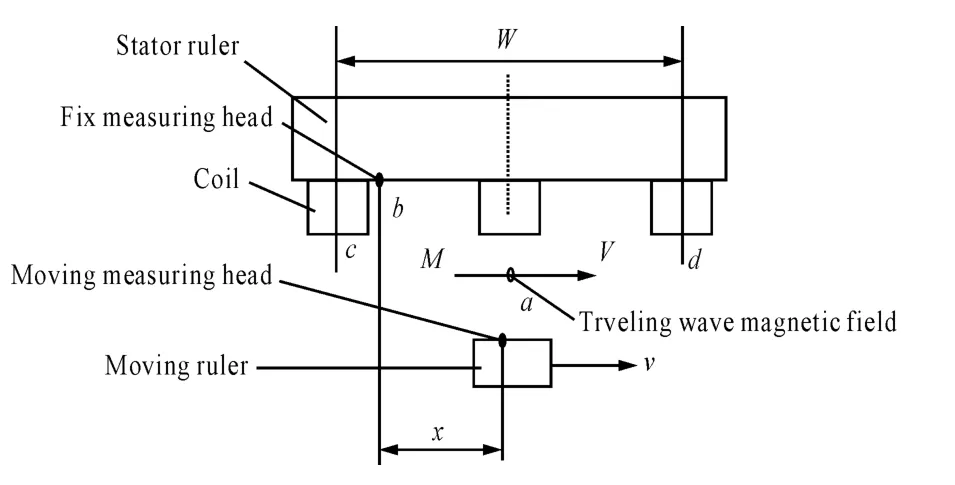
Fig.1 The linear time grating sensor principle
We use clock pulse to measure spatial displacement.As the key devices of data acquisition system,the controller and A/D chip,to a large extent,decide the performance index of data acquisition system.Therefore,the largest difficulty in designing the hardware circuit of linear time grating sensor is how to build the most appropriate A/D data sampling system[7].
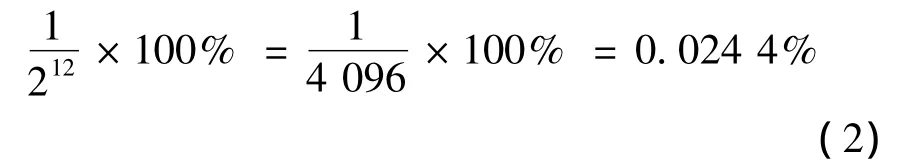
As for the selection of A/D converting circuit,we take the following aspects into consideration:firstly,the resolution parameter of A/D sampling system.Resolution is the smallest analog input of A/D converter,which shows the ability of processing the digits of digital code with binary digits.We choose 12-bit A/D converter whose resolution is 212,expressed in percentage as following:
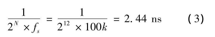
Since we use the pipelining structure technology,the conversion rate of high-speed A/D sampling is much faster than the conversion time[8].Secondly,we choose the frequency size that affect high resolution.We assume that the signal frequency of linear time grating sensor isfsand the sampling frequency isfA/D.The signal frequencyfsdirectly determines resolution as the minimum time.The signal frequencyfswe choose is 100 kHz.When the input-signal frequency is less than 100 kHz,there will be larger loss in ADC circuit,which is about 1 bit.When the input-signal frequency is far bigger than 100 kHz,such as 1 MHz,the secondary residual error of ADC will have a high degree of distortion.So it would be best to keep the input-signal frequency at the level of 100 kHz,and the minimum time of resolution is:2.44 ns.
Therefore,the sampling frequencyfA/Dis significantly related to whether ARM can complete the highspeed data read and write operations in real time.
3.The design of A/D converting circuit
The displacement measurement of linear time grating sensor needs data acquisition system with high resolution and high speed.The analog signals should be converted to digital signals and then be sent to controller for calculating,therefore,high requirement is attached to the speed and resolution of A/D sampling.Taking into consideration factors like power consumption,price,volume and compatibility,we finally decide to choose the AD7298BCPZ from ANALOG Company as the system modulus conversion chip.The AD7298BCPZ is a 12-bit successive approximation ADC with high speed and low power consumption which has an inbuilt temperature sensor.It uses a single 3.3 V power supply and its operating speed can top to 1MSPS.This device contains a sample-and-hold amplifier with low noise and wide bandwidth.
Fig.2 is the externalcircuitdiagram of AD7298BCPZ;three channels of AD7298BCPZ are connected to the ARM processor STM32F407VGT6.The high-speed A/D conversion and amplifying circuit should be placed as near as possible,and they are both required to be close to the filter.Only in this way can the output of A/D amplifier circuit have lowest parasitic load effect.Plus,A/D converting circuit is quite sensitive to the noise coupling to the input line.By using 10uH inductance,analog ground can be well separated from digital ground.

Fig.2 The external circuit diagram of AD7298BCPZ
4.The design of data acquisition system
4.1.Design of the system hardware
In terms of the controller in the data acquisition system,we choose STM32F407VGT6 microprocessor as the core of the whole system,whose hardware structure diagram of the sampling system is shown in figure 3.Under the action of excitation signal,the moving probe and fixed probe of linear time grating sensor generates a sensing signal,through filtering,amplifying and conditioning,and then making data conversion by the 12-bitA/D converter chip AD7298BCPZ,which converts the analog signal into digital signal.According to different uses,we store and analyze the sampling data in real time,and then we make real-time error correction and error compensation caused by temperature change in the ARM.The data will be delivered to PC by communication interface for further analysis and processing.The graphical interface uses QT technology;LED screen is used to show the interface and debugging information.By making use of tips in software interface and keyboard for controlling,the real time and accuracy of sampling data can be better achieved.
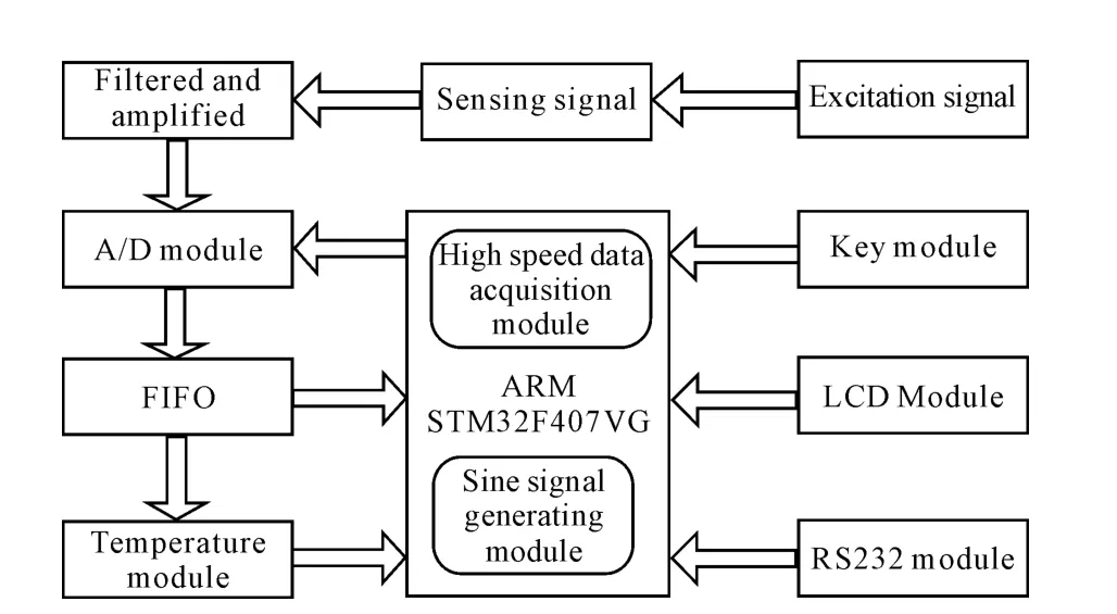
Fig.3 Hardware structure diagram of system
4.2.Design of the system software
According to the characteristics of the hardware system,the software platform can be achieved in the embedded Linux.The embedded Linux has a layered architecture,which can flexibly“insert”required function modules in accordance with the need of application program,truly achieves the software design thought of"high cohesion and low coupling",improving the security,stability and convenience of the embedded Linux. When designing the software process of the A/D converter of linear time grating sensor data sampling,we should pay particular attention to the fact that:after initializing the start of A/D converter,we should first clear instructions in the conversion result register,avoiding the unnecessary effect brought by last sampling data on the current sampling.The software flow chart of A/D converter of linear time grating sensor is shown in Fig.4.

Fig.4 Software flow chart of system
Since there are some requirements in terms of the real time of data sampling,in the process of configuring the kernel,we only keep those necessary function modules and unload the unnecessary ones required by the embedded system.The virtual memory management mechanism in kernel may affect its real time;we can shield it to enhance the real time of Linux.
Application program of the system consists of several functional modules,including modules like data acquisition,data processing,error correction,temperature compensation and data communication.Through operations to I/O interface,data acquisition collects data,and then reads and writes data in the equipment by using 4 functions like inb,inb_p,outb,outb_p.With reasonable use of the control and inquiry function for port using provided by kernel,conflicts in I/O reading and writing can be avoided.Data processing fulfills digital filtering,error correction,temperature compensation and other functions for data,and then exports data and saves to relevant files.The final step is to deliver the processed data to PC program.
5.Experimental result
Specific to the A/D converting circuit designed above,we made experiments on data acquisition of linear time grating sensor.By making data sampling in full scale and error correction and compensation for sampling data in real time,including compensation for errors caused by speed,acceleration,temperature change,etc.,we achieved automatic compensation and real-time correction for non-linear error in linear time grating sensor.Figure 5 shows the error curve whose peak value of error is 4.4um.Experimental result shows that the designed A/D conversion circuit(converting circuit)achieves real-time sampling of linear time grating sensor with high speed and high resolution,significantly improving the accuracy of linear time grating sensor.
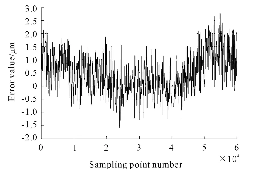
Fig.5 The curve of the sample point real-time error correction and compensation
6.Conclusions
Based on the data acquisition system of the linear time grating sensor designed by the combination of ARM controller and A/D converting circuit,by using Linux system which is characterized by high integration,better reliability and real-time performance as embedded developmentenvironment,this paper makes high-speed data sampling for time-grating signals with minimum resolving time as 2.44 ns in real time,and then makes error correction and compensation for sampling data in a more accurate way.It produces production cost for industrializing the linear time grating sensor,in the meantime,it also builds a solid foundation for the research on high-accuracy linear time grating sensor.
Reference:
[1]Hansen H N,Carneiro K,Haitjema H,et al.Dimensional Micro and Nano Metrology[J].Annals of the CIRP,2006,55(2):721-743.
[2]Chen Youping,Du Zhiqiang,Ai Wu,et al.Research on model of a new short-stroke linear motor and its experiments[J].Proceedings of the CSEE,2005,25(7):131-136.
[3]Ye Yunyue.Linear motor principle and application[M].Beijing:China Machine Press,2000:19-24,196-205.
[4]PENG Donglin,LIU Xiaokang,ZHAN Xinghong,et al.Time-grating sensor principle and development process of[J].Journal of Chongqing University of Technology ,2010(10):40-45.
[5]LIU Xiaokang,FEI Yetai,PENG Donglin,et al.Predictive measurement method for time grating sensor[J].Measurement Technology and Intelligent InstrumentsⅧ:Key Engineering Materials,2008:38-382,403-406.
[6]XIAO Kangliu,DONG Lin-peng,XING Hong zhang.Research on a Novel High-precision Intelligent Sensor.Mechatronic Systems and Materials[J].Solid State Phenomena,2006,113:435-441.
[7]Grace C R,Hurst P J,Lewis S H.A12-b 80-MS/s pipelined ADC with bootstrapped digital calibration[J].IEEE Journal of Solid-state Circuits,2005,40(5):1038-1046
[8]XUE L,SHEN Y Z,ZHANG X M.Method to test static and dynamic parameters o f A/D converters[J].Chinese Journal of Scientific Instrument,2004,25(4):72-74.
杂志排行
机床与液压的其它文章
- Strength Analysis and Optimization of a Torsion Beam Rear Suspension
- Development of Vibration Signal Acquisition and Analysis System for Machine Tools Based on LabVIEW
- Numerical Analysis and Experimental Research on Micro Milling Process with Cycloidal Tool Path
- Analysis of the Optimization of Gear Pump Pulsation Based on Matlab
- Simulation Evaluation and Performance Analysis of a Double Coil Magnetorheological Valve
- Remote Condition-based Maintenance Approach to Hydraulic System of Construction Machinery