Analysis and Discussion of the Key Technical Problems for the Screw Compressor Rotor Hobbing Machining
2013-06-02WANGXiaomingTIANQingqingXIONGGuoliangHEZhongyuWANChangbiao
WANG Xiaoming,TIAN Qingqing* ,XIONG Guoliang,HE Zhongyu,WAN Changbiao
1.Mechanical and Electrical Engineering College,East China Jiaotong University,Nanchang 330013,China;2.Shenyang Railway Administration,Shenyang 110000,China
1.Introduction
Screw compressors feature the advantages of high reliability,compact size,and lower easy deactivated spares,convenient in operation and maintenance,good dynamic balance,high adaptable,long lifetime and so on.They have been applied extensively in mine,chemical,power,metallurgy,construction,mechanical and refrigeration industries,especially in developed countries.The screw compressor utilization ration in developed countries such as Japan and United States has reached 60%~80%of the total production,while less than 2%in China.For the sake of improving the overall utilization,it is need to strengthen the research of screw compressor,effectively reduce the manufacturing cost,reduce the vibration and noise in the process of operation,and improve machining precision,so as to shorten the difference between the developed countries and keep up with the international pace[1].Screw rotor is the key part of screw compressor,as its complicate profiles and high processing requirements,so the total compression utilization,reliability,running stability and noise of screw compressor are depend on the machining precision of screw rotor to a great extent.Thus,seek an effective processing method to improve screw rotor machining precision is one of the most important task for the research of screw compressor[2].
2.Research status and existing problems of screw rotor machining
The quality of screw rotor is the key of the whole compressor performance and reliability,while the quality of screw rotor is depends on the following aspects:① the performance of screw rotor profile,②the machining precision of screw rotor tooth profile,③the rotor material and its way to heat treatment,and the first two aspects play dominant role.In a sense,screw rotor profile is relate to tooth profile processing,the machining precision of screw rotor tooth profile is determined by processing technology,screw rotor profile and processing technology mutual promote,and in the last promote the improvement of the whole performance of screw compressor[3].
At present time,methods used to the machining of compressor rotor including disc cutter milling method,generating method and grinding method.A-mong them,milling method belongs to discontinuous processing,if there are 4~6 teeth need to be machined,it must index milling one by one,this cause big index error.The milling method with the characters of low machining precision,low production rate and so on,it affects the reliability and efficiency of compressor,and increases the noise of rotor in working situation.The grinding method overcomes the disadvantage of milling method,it possesses the advantages of high grinding precision,surface roughness value Ra can reach 0.4m,tooth error can up to 5m;good molding process stability;it can obtain reasonable rotor meshing clearance and possesses deep grinding function.However,grinding also has its own limitation.If there is concave point in profile,it is hard to realize grinding.In the other hand,the grinding processing equipment is very expensive;it will bring economic pressure for most screw compressor manufacturefactory. Besides,the index problem still exists.Compared with milling method and grinding method,hobbing manufacture has many advantages,it realizes multi-teeth machining completed by one time feeding,it doesn’t need index,and doesn’t exist index error.Accordingly,hobbing manufacture owns the features of high production rate,high tooth machining precision and low pitch error.This method is applicable for producing compressor rotors with small outer diameter and large batch[4-5].
Hobbing manufacture can not only improve rotor machining precision,but also save machining time,but realize the screw rotor processed by hobbing in our country at present need to solve the following two key technical problems:the first one is to develop and improve the screw compressor in order to develop rotor profile fit for hobbing processing;another way is from the point of cutting tool,there is no need to change rotor profile,we only have to research hob cutting tool design theory,the cutting tool is used to manufacture screw of unilateral asymmetric cycloid with sharp point—pin tooth circular arc tooth profile;the second is to research the associated special screw rotor gear hobbing machine bed.As the screw rotor with less teeth and big helical angle,so it is difficult to process by general gear hobbing machine.Besides,because of the existing of gear hobbing machining error,the quality and precision of screw rotor is severely affected.
3.Problems and solutions of the hob cutting edge design
Fig.1 shows the transverse profile of the asymmetric Yin screw rotor,it consists of line“ab”,arc“bc”,extended epicycloid“cd”and radial line“de”.As there is no common tangent on the crosspoint d of line“de”and extended epicycloid“cd”,so there is a sharp point at“d”.In solving axial cutting edge meshes with rotor,the result shows the hob cutting edge separate,in other words,the“d1”and“d2”misalign,as show in Fig.2.In order to process the correct screw rotor profile,it must ensure the sharp point“d”is not be cut off by hob.In this situation,academia put forward the following two designs for hob cutting edge to solve the sharp point issue:one is precise calculation based on normal rack,the other is calculate based on meshing contact line.

Fig.1 Transverse profile of Yin screw rotor

Fig.2 Sketch of hob axial cutting edge
3.1.Precise calculation based on normal rack
Due to the big helical angle of screw compressor rotor,precise calculation method must be adopted to design hob cutting edge,the normal rack is not fittable,otherwise the error is big.Using the concept of common rack to solve the separate part profile,that is to say,first find the track of sharp point’s detach curve equation formed on rack cutter,then according to this equation calculate cutting edge equation of the separate part profile meshed with hob cutting edge,this precise calculation makes the space meshing problem change to plane meshing problem[6].
Due to the existence of sharp point“d”,rack tooth profile which is work out according to the gear shape normal theory will appear two detach curves similar to Fig.2,the two separation points’coordinatesd'(x1,y1)andd″(x2,y2)can be work out in workpiece transverse plane rackot1.Apparently,sharp point d moves on the rack tooth forms the separation section when the workpiece does meshing movement relative to rack.In order to make the rack tooth profile meshes properly with workpiece,i.e.the sharp point d can’t be cut off by rack cutter,thed'd″curve equation on the rack must be work out.As show in Fig.3,the mesh of workpiece and transverse rack can be thought as workpiece pitch circle does pure roll on the rack section line.When the workpiece rolls from point o to pointo1,the movement path equation of sharp point d on rack cutter ot1 can be written as Eqs.(1).
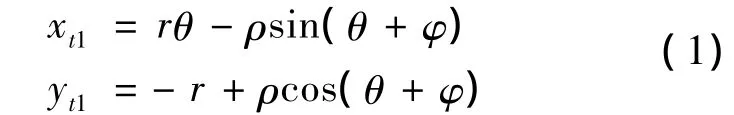
Where ρ is the profile length of od,ris the pitch circle radius of workpiece,θ is parametric variable,and θ1≤θ≤θ2,φ is the radial angle of straight lineoeandycoordinate.

Fig.3 Formation of d'd″curve on workpiece transverse tooth profile
Plug the coordinatesd'(x1,y1)andd″(x2,y2)in Eqs.(1),then the pointsd'andd″corresponding to the range value θ1and θ2can be calculated.
Eqs.(1)is the curve equation ofd'd″on the rack.Set the helical angle of Yin screw rotor as lefthanded angle β1,and set hob helical angle as righthanded angle β2,the meshing position of workpiece,hob and common rack is shown in Fig.4.Only when the curve equation ofd'd″on the rack was work out,the cutting edge profile meshed with curved'd″can be calculated,as shown in Fig.2.As shown in Fig.4,xt1andyt1converse to hob transverse rack coordinateotcan be written as Eqs.(2).

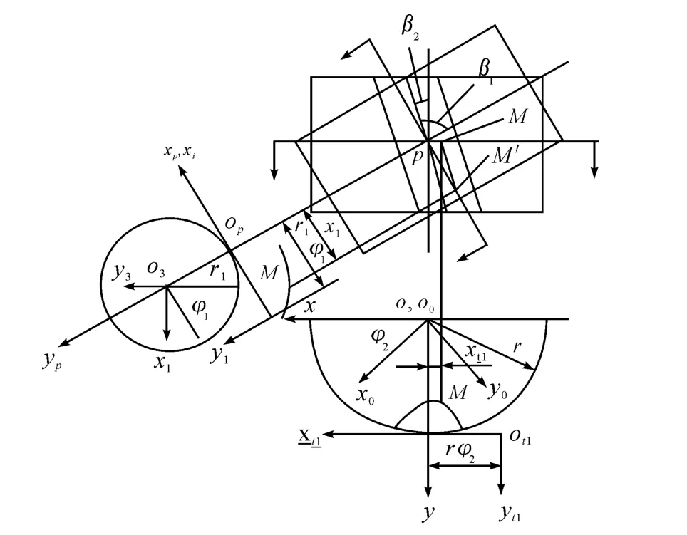
Fig.4 The coordinates and position relationships among workpiece,hob and common rack
According to Eqs.(2)and gear shape normal theory,hob basic worm tooth profile equation meshed with hob transverse track can be calculated,as shown in Eqs.(3).Where φ stands for the hob worm turning angle when a pointMin workpiece begins to mesh and changes to contact point,uis the angle of tangent on pointMand coordinatexpwhen the pointMbegins to mesh,r1is the hob basic worm pitch circle radius.
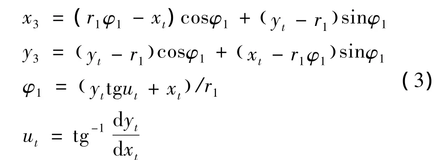
Series of coordinate points on separation section of curve can be calculated according to Eqs.(3),then makes the points spiral movement around the hob basic worm axis,in this way,transverse equation of hob worm separation section can be obtained.Divide along its axial,cutting tool axial edge equation of corresponding hob separation section is work out.
3.2.Calculate based on meshing contact line
Screw rotor hobbing machining process,whose essence is the screw rotor helical surface contact with hob helical space,and the space position of the forming contact line remains the same.According to the property that contact line’s space position remains the same,contact condition of hob cutting edge design is deduced,then by the contact condition calculate hob cutting edge of machine screw rotor tooth[7-8].
Establish the Cartesian coordinate system as shown in Fig.5.WhereO1X1Y1Z1andO2X2Y2Z2are static coordinates,coordinatesX1andX2are in the same straight line,the distance between the two coordinate origino1ando2is set asA,O1x1y1z1andO2x2y2z2are dynamic coordinates of screw rotor,coordinate axisz1、z2coincide withZ1、Z2,respectively.
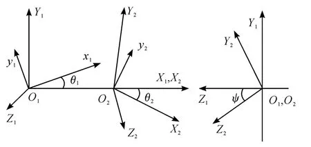
Fig.5 Right hand space Cartesian coordinate system
Set the helical surface of screw rotor 1 as righthanded,its parameter equation of transverse profile in dynamic coordinateO1x1y1z1as shown in Eqs.(4).

While helical surface parameter equations in static coordinateO1X1Y1Z1is shown in Eqs.(5).
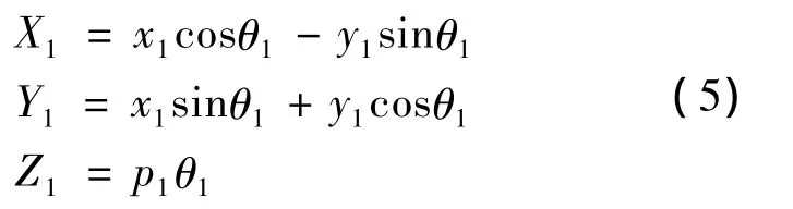
Wherepis the screw characteristic number of helical surface.
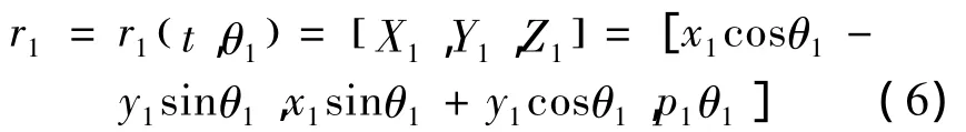
A point’scoordinate in static coordinateO1X1Y1Z1in contact line can be expressed in the form of vector as shown in Eqs.(6).
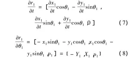
The corresponding two tangent vectors across contact point in coordinate systemO1X1Y1Z1can be indicated as Eqs.(7)and Eqs.(8).
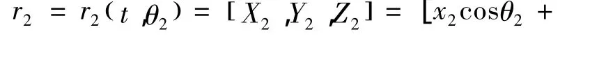
The vector of contact point in coordinate systemO2X2Y2Z2can be indicated as Eqs.(9).

By the use of coordinate transformation between coordinate systemsO1X1Y1Z1andO2X2Y2Z2as well as the relationship between unit vectors,the tangent vector inO1X1Y1Z1is obtained in form of Eqs.(10).

As the tangent vector across any contact point in the same plane,in other word,the mixes volume of the above three tangent vectors is zero,as shown in Eqs.(11).

Substitute Eqs.(7)~ (9)in Eqs.(11),and the helical surface space geometry equation is obtained,as shown in Eqs.(12).
Ψ is the angle of coordinateZ1andZ2,substitute the helical surface parameter equation(5)in contact condition equation(12),the transcendental equation aimed to solve hob cutting edge can be gained,as shown in Eqs.(13):

whereAcis the space distance between axisZ1andZ2,i.e.the installment center distance,which is known as well as hob screw characteristic numberp.If a point in transverse plane tooth profile whose coordinate is(x1,y1)and its derivative is dy1/dx1are known,then the corresponding point θ1can be obtained.Substitute the value θ1in Eqs.(6),then the contact point coordinate(X1,Y1,Z1)in coordinate systemO1X1Y1Z1was gained,by using coordinate transformation the coordinate(X2,Y2,Z2)in coordinate systemO2X2Y2Z2and the corresponding hob cutting edge coordinate(Z2,(X22+Y22)1/2)can be obtained.
4.Key technology research of conventional gear hobbing machining
4.1.The existing problems and solutions of conventional gear hobbing machining
The tooth number of screw rotor is less,usually the number is 4~8,and the helical angle is big,about 30°~ 60°.Machining screw rotor using gear hobbing machining similar to Y3150E will meet the following three troubles:
1)Adjust tool rest according to the requirement of the screw rotor helical angle,the left of tool rest or the movable bearing will generate interference with workbench,and the effective stroke length of tool rest vertical feeding is limited.
2)Arc part in front active arm of outer bracket and arc part in the left of tool rest will generates interference with tool rest left side,as a result,cutting tool can’t close to the being processed gear billet outer circular surface of screw rotor.
3)Due to the less tooth number of being processed screw rotor,thus the relative speed of workbench is high,the abrasion of indexing worm gear pair is increased,and then the machining accuracy of tooth circle is affected[9].To sum up,for machining screw rotor with less tooth number and big helical angle,conventional gear hobbing machining is not suitable,and the effect is not obvious,so it is need to develop or introduce special screw gear hobbing machining equipment.
4.2.Analysis of gear hobbing machine machining error
With the increase demand of high precise screw rotor applied in fields such as mining,chemical,power,metallurgy,construction,machinery and refrigeration,the requirement for gear hobbing machine accuracy and machining accuracy is higher.However,as the gear hobbing machine with high speed,high efficiency,long working time,and the machine tool part’s movement and transmission are complex,therefore,gear hobbing machining error has great influence on machining quality.The greatest impacts on machining error mainly include three factors[10],which are hobbing force,vibration and thermal deformation.
1)thermal error.In the process of gear hobbing machining,a lot of heat will generate,mainly includes hobbing heat,friction heat and motor heat,these heat absorbed by machine tool key parts after conduction,radiation and convection,which make uneven heat in parts,as a result temperature difference forms among the parts,and causes the upright become bend,the bed elongation and thermal deformation.Moreover,positional deviation between hob and workpiece spindle center distance is formed,and then the machining error of screw rotor is generated.
2)Bed machiningerrorcaused by hobbing force.Hobbing force makes the hob and the workpiece spindle bending deformation,spindle center distance position offset,the most affected is X direction position,then the machining error formed,this kind of error called force-induced error.Besides,hobbing force increases the bearing reaction force of hob spindle on both ends,makes the bearing load situation worse,aggravates the wear and tear,reduces or affects the machining accuracy of machine tool.
3)Screw rotor machining error caused by hobbing vibration.In high speed cutting process,processing work is not stable,hobbing force makes the cutter and the workpiece self-induced vibrate strongly,which leads to the position of center distance produces vibration displacementorslight change,affects the machining precise,and then causes the screw rotor machining error.
5.Conclusions
The processing of compressor screw rotor is one of the most important issues in the manufacture of compressor,it is difficult and has high accuracy requirement.At present,most screw compressor manufacture factories in our country still adopt milling machining with low accuracy and low efficiency,this is seriously affect the quality of the screw compressor.As a new kind of machining method for screw compressor rotor,though hobbing machining possesses many advantages over milling method,the realization of hobbing machining still has many technical problems need to solve,mainly includes the design of hob cutting edge,deep research of hobbing process and develop special screw gear hobbing machine.
To sum up,it is important to research hob cutting edge design methods,hobbing process and special screw gear hobbing machine aimed to solve the problem that screw rotor with less tooth and big heli-cal angle.At the same time,set up screw rotor machining thermal error compensation models for different types of gear hobbing machines and different seasons;meanwhile,develop compensation model of hobbing machining error caused by the hobbing force and hobbing vibration is the inevitable trend of technology development.In the near future,advanced hobbing machining process will become the main method for the machining of screw compressor rotor,and play a positive role on the quality improvement of screw compressor.
[1]LI H J.Research on Machining Method and Special NC Equipment of Rotor Helical Convolute of Single Screw Compressor[D].Shenyang:Shenyang University of Technology,2007.
[2]SUN X W,WANG X.Research on NC Machining of the Screw Rotor of Single Screw Compressor[J].Machine Tool&Hydraulics,2008,36(4):255-257.
[3]WU X J.Grinding forming of the screw compressor[J].Fluid Machinery,2000,28(7):33-34.
[4]Sang-Yoon Park,Hi-Koan Lee.A Study on the Machining of Compressor Rotors Using Formed Tools[J].INTERNATIONALJOURNALOFPRECISIONENGINEERING AND MANUFACTURING,2010,11(2):l195-200.
[5]CHEN L M.Grinding of screw compressor[J].Mechanical Engineer,2005(2):89-91.
[6]LIU J H.Screw compressor rotor machining technology and the discussion of key technology problems for hob design[J].Chinese Mechanical Engineering,2000,11(4):382-384.
[7]Peng X Y,WU H G,XING Z W.Design of the Hobbing Tool Profile for Manufacturing Screw Rotors[J].Journal of Xi’an Jiaotong University,2003,37(1):103-104.
[8]YE H C,SUN Y.Research and Application of 3D Modeling of Gear Based on Gear-hobbing Simulation [J].Machine Tool&Hydraulics,2007,35(12):75-77.
[9]ZHENG G H,YANG J.Cylindrical gear with less tooth and big helical angle machined by Y3150 gear hobbing machine[J].Mechanical Engineer,1991(1):40.
[10]YANG Y.Research on Machining Error and Compensation for Large-scale Numerical Control Gear Hobbing Machines[D].Chongqing:Chongqing University,2012.
杂志排行
机床与液压的其它文章
- Strength Analysis and Optimization of a Torsion Beam Rear Suspension
- Development of Vibration Signal Acquisition and Analysis System for Machine Tools Based on LabVIEW
- Numerical Analysis and Experimental Research on Micro Milling Process with Cycloidal Tool Path
- Analysis of the Optimization of Gear Pump Pulsation Based on Matlab
- Simulation Evaluation and Performance Analysis of a Double Coil Magnetorheological Valve
- Remote Condition-based Maintenance Approach to Hydraulic System of Construction Machinery