Monitoring Method for the Electrical Properties of Piezoelectric Transducer
2012-07-25LIWen李文ZHUZeqi朱泽琪
LI Wen(李文),ZHU Ze-qi(朱泽琪)
(College of Mechanical and Electrical Engineering,North China University of Technology,Beijing 100144,China)
Introduction
Cutting force monitoring,as an important part of the monitoring and diagnosis of manufacturing process,is a key technology in advanced manufacturing[1-2].The monitoring of ultrasonic vibration cutting force has an important meaning for the improvement of machining stability and efficiency.With the wide application of vibration cutting technology in the aviation,aerospace and other fields,the monitoring of vibration cutting force is particularly important.
Currently,the monitoring methods of cutting force mainly use the dynamometer and other means.The cutting force can reflect the tool wear,tool breakage,cutting chatter and other characteristics[3-6].But the dynamometer must be fixed on the machine.This needs to design a special fixture,even needs to change the machining tool structure.This method which uses the dynamometer to monitor the cutting force is limited its application.
In the paper,the relationship between the elliptical vibration cutting force and the piezoelectric transducer impedance is researched,and a new ultrasonic elliptic vibration cutting monitoring method based on the electrical properties of piezoelectric transducer is proposed.The method has a great significance in the popularizing application of ultrasonic vibration cutting and processing technology.
1 Influence of Electrical Properties of Transducer on Cutting Force
As a load of piezoelectric transducer,the cutting force is an important parameter,which can represent the dynamic behavior of process.Thus,the stability of the cutting process can be indirectly monitored by means of the signal change of cutting force[7].The change in cutting force affects the variation of electrical properties of transducer.The conclusion that the electrical impedance of transducer can accurately reflects its load change has been drawn by analyzing the relationship among the electrical impedance,electrical parameters and output load of transducer.
1.1 Relationship Between Electrical Parameters and Output Load of Transducer
Usually,a cutting load applied to the output terminal of transducer can change not only the resonant frequency of transducer,but also its impedance[8-9].The relationship among the input voltage,input current and output load of transducer can be expressed by a four-terminal network shown in Fig.1[10].

Fig.1 Four-terminal network of transducer acoustic system
The mathematical expression is
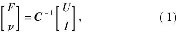
whereUis the input voltage,Iis the input current,νandFexpress the mechanical load and vibration velocity of transducer output,respectively,Cis the transfer function matrix of transducer that is a complex matrix related to the transducer characteristics.According to Eq.(1),when the loadFchanges,the input voltageUand input currentIare changed accordingly,but Eq.(1)describes the transient relationship between the input and the output,the involved physical quantity and the transfer matrixare the complex numbers.The measurement and calculation are very complicated,so it is difficult to use the above relationship directly in cutting process.
1.2 Effect of Electrical Impedance of Transducer on Output Load
The ultrasonic piezoelectric transducer is a nonlinear time-varying system,The different operating frequencies have a significant effect on impedance and mechanical vibration characteristics of ultrasonic piezoelectric transducer.The electrical characteristics of piezoelectric transducer are expressed as a series connection of a resistorRand a reactanceX,that isZ=R+Jx.The equivalent circuit is shown in Fig.2,whereL1is the dynamic inductance of transducer,C1is the dynamic resistance of transducer,RLis the load resistor of transducer,andR1is the dynamic resistance.When the output load of transducer increases,the equivalent external load resistanceRLof equivalent circuit model decreases,R1decreases,and the round radius of the transducer impedance becomes small.R1represents the loaded dynamic resistance of transducer which the impedance circle is represented by dashed line,as shown in Fig.2.It can be seen from Fig.2 that,as the load increases,the impedance is reduced,but in the upper left area of impedance circle,the load increases,and the impedance increases.In the paper,the impedance circle lies in the area,in which the load and the impedance increase.That is,when the cutting force increases,the impedance increases.The transducer load is always changing during vibration cutting,and the transducer impedance correspondingly changes.The change of impedance is bound to cause the change in the vibration characteristics of transducer output.The stability of transducer output vibration directly impacts the effect of ultrasonic vibration cutting.Therefore,the operating frequency of the transducer should be selected in the relatively stable area of load-impedance characteristics.

Fig.2 Quivalent circuit model of transducer

Fig.3 Impedance circle change before and after loading
Accordance to the above relationship,the change in cutting force can be derived from the electrical parameter change of transducer,thereby obtaining more accurate cutting state of ultrasonic vibration cutting.The processing parameters can be compensated and adjusted in accordance with the actual state.Near the parallel resonant frequency,the relationship between the resistance and reactance of transducer is expressed by Eq.(2)which graph is a circle in the complex impedance plane[11].The circle is expressed by the thick solid line in Fig.3.

When the transducer output load increases,the dynamic resistanceR1is reduces,the transducer impedance radius which the dotted line drawn showed in Fig.3 is smaller.In the most area of impedance circle,transducer impedance is reduced with increasing load.In the paper,the left upper region of resonance zone is chosen.When cutting force increases,transducer impedance increases.According to the above relationship,transducer impedance change can reverse draw cutting force changes,so can obtain more accurately actual cutting state of ultrasonic vibration cutting,and according to the cutting state,the processing parameters is compensated and adjusted.
2 Measurement System for Electrical Properties of Elliptical Vibration Transducer
As the operating voltage of piezoelectric transducer is from volts to kilovolts,the operating frequency is about 20 kHz,its electrical properties are usually difficult to measure.An online measurement system for electrical properties of ultrasonic elliptical vibration transducer was designed based on the actual requirement.The system can also sample and process the currents and voltages of two branch piezoelectric vibrators,and the phase difference between their current and voltage.It also has the capability of sampling the phase difference between the voltages of two branch piezoelectric vibrators.
The circuit uses three separate sampling units,each unit can independently measure the voltage,current and phase difference signal of a single transducer.The two sampling units are respectively responding to the two branches of transducer.A square wave signal of voltage generated by the zero-crossing comparator of phase discrimination circuit is output directly to the third sampling circuit unit.
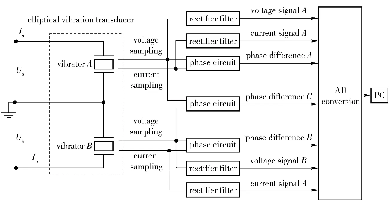
Fig.4 Schematic diagram of measurement system
3 Monitoring Experiment of Vibration Cutting Force
The experiments are done by using the selfdesigned double curved ultrasonic elliptical vibration system and ultrasonic elliptical transducer electrical property measurement system.The experimental platform is shown in Fig.5.The cutting state is monitored on the ultrasonic vibration cutting force measurement system,as shown in Fig.5(a).The KISTLER piezoelectric dynamometer is used to measure the cutting force in cutting process.Fig.5(b)shows the ultrasonic transducer electrical property on-line measurement system which achieves the on-line measurement and collection of transducer electrical properties,its operating frequency is 500 Hz.
The experimental processing conditions are listed in Tab 1.the cutting depth is 30 μm,60 μm and 120 μm,respectively.

Tab.1 Monitoring processing conditions of cutting force
The elliptical vibration cutting force and the corresponding of two way transducer electrical signals were measured by experiment.The measurement parameters include voltage,current and phase difference of two branches,the measured data is shown in Fig.6.

Fig.6 Elliptical vibration cutting force and transducer electrical signal
In Fig.6(a),FyandFzexpress the penetration force of a cutting tool and the cutting forcel during elliptical vibration cutting trust force,respectively.The penetration force of a cutting tool is negative because its direction is contrary to the measuring direction of dynamometer;Ub,Ibandθbexpress the voltage,current and voltage-current phase difference of piezoelectric vibrator along cutting direction,respectively,which is related to the cutting forceFz;θabis the voltage phase difference of two piezoelectric vibrators and characterizes the change in elliptical vibration.It can be seen from Fig.6 that the elliptical vibration cutting forcesFyandFzincrease with the increase in the cutting depthap.The electrical parameters of two branch transducers change with the change in cutting force.As shown in Fig.6(a),(b)and(c),since the transducer is a nonlinear system of which voltage is generated by resonance model,it is difficult to ensure the transducer electrical parameter is monotonically changed,so the cutting force state can not be characterized by an electrical parameter.
The transducer impedance monotonically increases as the load increases at the chosen operating frequencies.The impedance of transducer includes current,voltage and phase difference.In Fig.3,before and after loading,the impedance circle has no other intersection point except for the tangent intersection atf″,therefore,the transducer impedance can ensure that the electrical parameters corresponds to the cutting force.The impedance curves of two branch way transducers can be obtained from Fig.6,as shown in Fig.7.Fig.7 shows that the transducer resistance and reactance monotonically increase as the load increases.So the total impedance of the transducer also changes monotonically with the increase in cutting load.
Figure 8 shows that the relationship between impedance and cutting force of two branch elliptical vibration transducers is mapped in coordinate system,and the total impedance monotonically increases as the cutting force increases.

Fig.8 Relationship between impedance and cutting force of two branch elliptical vibration transducers
It can be found by repeating the above experiments that the change relationship between cutting force and transducer electrical parameters has high repeatability,so proving that the method of using transducer electrical properties to reflect the change in cutting force is high reliability.
4 Conclusions
1)As a nonlinear system,the transducer is difficult to fully reflect the change in load by a single electrical parameter.Therefore the cutting force state can not be characterized by an electrical parameter.Transducerimpedance characteristicsreally reflectthe change in load,which includes voltage,current and phase.
2)The change relationship of cutting force and transducer electrical parameters has high repeatability.
3)The method of using transducer electrical properties to monitor the cutting force,which needs to add other sensors,can monitor the cutting force in real time and measure the cutting force at some places,and it is not suitable for cutting force sensor.
[1]XU Chung- guang,WANG Xin-yi,XIAO Ding-guo.A new method for the on-line monitoring of tool state[J].Journal of Beijing Institute of Technology,1994,14(1):49-51.(in Chinese)
[2]FENG Ji-ning,LIU Bin,DIAN Zhe-jun,et al.Condition detection on cutting tools wavelet-based neural network[J].China Mechanical Engineering,2004,15:321 -324.(in Chinese)
[3]GAO Hong-li, XU Ming-heng. Tool wear monitoring based on dynamic tree[J].Chinese Journal of Mechanical Engineering,2006,42(7):227-230.(in Chinese)
[4]LIU Xian-li,YUAN Zhe-jun.The measurement of cutting temperature by equivalent themocouple methods[J].Acta Metrologica Sinica,1999,(3):187 -192.(in Chinese)
[5]LI Guang-jun,HAN Feng-qi,XU Yong-li,et al.On self-adaptive vibration tapping of titanium alloy[C]∥International Technology and Innovation Conference,2006:236-240.
[6]LI X Q,Wong Y S,Nee A Y C.Tool wear and chatter detection using the coherence function of two crossed accelerations[J].International Journal of Machine Tools and Manufacture,1997,37(4):425 -435.
[7]WU Bo-da,QU Xing-tian,et al.On-line monitoring of cutting stability[J].Journal of Vibration Engineering,1997,10(1):71 -75.(in Chinese)
[8]GAO Tian-fu,ZENG Juan,PENG Da-yong.Analysis of characteristics of broadband matching for piezoelectric ceramic transducer[J].Acta Acustica,2007,32(2):97 -100.(in Chinese)
[9]Gordon S K.Acoustic waves-devices,imaging and analog signal processing[M].New Jersey:Prentice Hall,1987:37-41.
[10]DONG Zhen,YAN Jiu-chun.On-line measurement of load impedance in ultrasonic plastic welding[J].Journal of Welding,1999,(SI):51 -55.(in Chinese)
[11]JIANG Xing-gang,ZHANG De-yuan.Matching theory of ultrasonic transducer at its passed inherent resonance zone[J].Chinese Journal of Mechanical Engineering,2007,43(3):182-186.(in Chinese)
猜你喜欢
杂志排行

Defence Technology的其它文章
- An Investigation on a Tin Fixed Abrasive Polishing Pad with Phyllotactic Pattern for Polishing Wafer
- An Approximate Calculation Method for Lateral Trajectory Correction
- Lift Enhancement and Oscillatory Suppression of Vortex-induced Vibration in Shear Flow by Loentz Force
- A Study on Criteria for Barrel Lifetime
- Research on Microcrack Extension Mechanism of SiCp/Al in the Machining Process
- Molecular Dynamic Simulation for HMX/NTO Supramolecular Explosive