Testing for Nonlinearity in Dynamic Characteristics of Vertical Upward Oil-Gas-Water Three-phase Bubble and Slug Flows*
2012-03-22ZHULei朱雷JINNingde金宁德GAOZhongke高忠科DUMeng杜萌andWANGZhenya王振亚
ZHU Lei (朱雷), JIN Ningde (金宁德)**, GAO Zhongke (高忠科), DU Meng (杜萌) and WANG Zhenya (王振亚)
School of Electrical Engineering & Automation, Tianjin University, Tianjin 300072, China
1 INTRODUCTION
Oil-gas-water three-phase flow widely exists in the oil well production and oil-gas transportation. Due to the interplay among many complex factors such as fluid turbulence, phase interfacial interaction, and local relative movements between phases, three-phase flow exhibits highly irregular and unsteady flow structure.Consequently, the investigations on three-phase flow dynamical characterization are very limited. In addition, the well logging interpretation depends largely on the analysis of flow characteristics. So it is important to develop an effective approach to investigate oil-gas-water three-phase flow characteristics from measured fluctuation signals.
In early studies of vertical upward oil-gas-water three-phase flow, Tek [1] treated two immiscible liquids as an equivalent pseudo-phase and predicted the pressure loss by using an empirical correlation. Shean[2] conducted the Nujol-water and Nujol-water-air flow loop test in a vertical upward 19 mm ID pipe and investigated the relationship between pressure drop and oil phase fraction in the phase inversion of continuous phase in mixture. Guoet al. [3] conducted three-phase flow loop test in a 125 mm ID pipe and divided flow pattern into bubble flow and slug flow by using visual observation. Chen [4] pointed out that the flow pattern transition of oil-gas-water three-phase flow mainly depended on superficial gas and liquid velocity and classified the flow pattern into oil-in-water and water-in-oil type flows. Woodset al. [5] carried out three-phase flow experiment in a 26 mm ID Perspex pipe, and they summarized the three phase flow pattern maps and proposed the predictive equation for phase inversion of continuous phase. More recently, Zhouet al. [6] used high-speed camera to capture six different types of dynamic images of oil-gas-water three-phase flows in the vertical upward pipe and extracted the chaotic invariant from synthetic image gray level time series. Gaoet al. [7, 8] developed a complex network-based method to uncover the nonlinear dynamics leading to the formation of different patterns in multiphase flow systems and achieved interesting and significant results.
Since the multiphase flow is a typical nonlinear system, characterizing three-phase flow from measured signals has attracted much attention and some progresses have been made in applying the nonlinear analysis method [9-15]. However, the previous studies mainly focused their studies on the flow pattern indentification and did not pay much attentions on dynamical characteristic discrepancy for the same kind of flow pattern. In recent years, the surrogate data method proposed by Theileret al. [16] shows great advantages for analyzing time series measured from nonlinear dynamic system [17, 18], especially for analyzing EEG (electroencephalography) and ECG(electrocardiography) data [19, 20]. In particular, Linet al. [21] obtained the local voidage fluctuation signals using optical transimission probe and analyzed nonlinear dynamics in bubbly columns. However,three-phase flow is more complex and investigation on its dynamical characteristics is very limited. In this regard, based on the conductance fluctuating signals measured from vertical oil-gas-water three-phase flow experiments, we explore the dynamic characteristics of oil-in-water type bubble and slug flow under different flow parameters in detail, using the surrogate data method.
2 EXPERIMENTAL FACILITY AND DATA ACQUISITION
2.1 Experimental facility
The oil-gas-water three-phase flow experiments in vertical upward 125 mm ID pipe were carried out in multiphase flow loop facility of Tianjin University.The detail description of the experimental facility refers to [22, 23]. The whole test section is 3.9 m high,and located 3 m above the entry section for air and oil-water mixture to allow the flow pattern becomes well developed.
The real-time monitoring system for three-phase flow consists of the vertical multi-electrode array(VMEA) shown in Fig. 1 (a) and a mini-conductance probe array in Fig. 2, and their location was 3 m from the inlet. The VMEA consists of eight stainless steel ring electrodes made of Cr1Ni18Ti9, which are axially separated and flush mounted on the inside wall of the test section. Sensors A and B are respectively the upstream and downstream sensor and used to measure the axial velocity, based on the cross-correlation technique. Sensor C is the mean volume fraction sensor.E1and E2are the excitation electrodes and connected with a 20 kHz sinusoidal signal. The signal modulating module consists of three sub-modules: differential amplifier, phase-sensitive demodulator and low pass filter. As shown in Fig. 1 (b), the distance between the exciting electrodesZe=250 mm, the two exciting electrodes E1and E2are positioned atz=±Ze/2 respectively, the height of the exciting electrodeHe=5 mm and the height of the measuring electrodeHm=3 mm. Otherwise, the distance between the volume fraction sensorsZh=170 mm, the distance between the cross-correlation sensors A and B isZcc=110 mm andDcc=20 mm is that between upstream correlation electrodes C1and C2as well as between C3and C4.

Figure 1 The geometry and parameter definition of VMEA conductance sensor

Figure 2 Structure diagram of mini-conductance probe array

Figure 3 Test section of VMEA sensor and mini-conductance probe array
For the purpose of local parameters measurement,we adopted a mini-conductance probe array to detect the continuous liquid. As is shown in Fig. 2 (a), the mini-conductance probe is mainly composed by the bare needle electrode and conductive casing, and the space between them is filled with insulation. For the purpose of flow pattern identification, five miniconductance proves were arrayed in equidistance at test section. Fig. 2 (b) shows the installation schematics of five mini-conductance probe. The inserted depth of probe A, B, C, D, E are respectively 1/8 ID, 1/8 ID,1/4 ID, 1/4 ID and 1/2 ID, where ID=125 mm is the pipe inner diameter. The distance of probes in the flow direction is 150 mm. When the needle electrode is surrounded by conductive liquid-water, the circuit loop forms between needle electrode and casing, and output signals are at low voltage; when the needle electrode is immerged in non-conductive liquid, the circuit is broken, the output signal will perform high voltage. The circuit between the needle electrode and conductive casing usually presents some feature of equivalent resistance to indicate the mixing degree of oil and water mixture around the sensor. We have used the same mini conductance probe array to accurately identify the inclined oil-water two-phase flow patterns[22]. We indicated that the mini conductance probe signals cannot only reflect the oil slug, but also clearly characterize the small oil bubbles.
The signals can be recorded by National Instrument Corporation’s data acquisition cards PXI 4472 and PXI 6115 operated by LabVIEW software. In experiment, the signals from the conductance probe were acquired by DC-coupled mode and the signals from the VMEA sensor were acquired by AC-coupled mode.The sampling rate and time were 400 Hz and 50 s,respectively. Compared with the time-frequency of the flow patterns, the sampling of the conductance system we chose can satisfy the need of the experiment and can well represent the frequency characteristics of different flow patterns.
The experimental media were 15#industry white oil with density of 856 kg·m-3and viscosity of 11.984 mPa·s (40 °C), air and tap water. Conductance fluctuating signals were acquired from the VMEA sensor and mini-conductance probes by increasingUsggradually for each combination offoand the flowrate of oil-water mixture. This experimental procedure was convenient to observe gas-liquid flow pattern transition trend affected by oil for lowfoand the influence of gas on oil-water flow patterns and the phase inversion of liquids for highfoin the same total liquid flowrate. The ranges of three-phase flowrates were as follows: the total liquid flowrates were 0.83, 1.67, 2.5 and 3.33 m3·h-1, respectively, andfowere 0.1, 0.2, 0.3,0.4, 0.5, 0.7, 0.9 and gas flowrates ranged from 0.33 to 7.5 m3·h-1. Due to the upper limit of gas flowrates,we mainly observed bubble and slug type flow patterns in large diameter pipe.
Oil-water-air flow patterns were detected by mini-conductance probe. By observation, at low liquid flow velocity and lowfo, the oil-water phase was not completely mixed to sub-millimeter scale, oil droplets showed more random behavior, the slip velocity between oil and water was obvious, and the surface of air bubble was mostly occupied by water [15]. The output signals of mini-conductance probes were mainly at low voltage (Fig. 4). At lowUsgandfo, the gas exists in the form of air bubbles dispersed in the oil and water mixture, and oil droplets disperse in the continuous water phase. Correspondingly, we define this flow pattern as oil-in-water type bubble flow. With the increase ofUsg, air slug appears due to increase of bubble concentration, and there exist small air bubbles and oil droplets between two slugs. Correspondingly,we define this flow pattern as oil-in-water type slug flow.Between these two flow patterns, there is an oil-in-water type bubble-slug transitional flow. The schematic diagram is shown in Fig. 5. Details about the experiment may be referred to our recent paper [15].
2.2 Conductance signals analysis of bubble and slug flows

Figure 4 Mini-conductance probe signals of three typical flow patterns with oil-in-water (Usg=0.0019 m·s-1, Usw=0.017 m·s-1)

Figure 5 Schematic diagrams of three oil-gas-water three-phase flow patterns○ air; ● oil;oil in water dispersion

Figure 6 Conductance fluctuating signals of oil-in-water type bubble flow with changing Usg (flowrate of oil and water mixture is 1.67 m3·h-1, fo=0.1, Uso=0.0039 m·s-1, Usw=0.034 m·s-1)
In experiment, we found that oil-in-water type flow mainly appears at lowfo(fo=0.1-0.5). The oil-in-water type bubble flow will convert to slug flow with increasing gas flowrate and slug flow appears at smallerUsgwith increasingfo, mainly due to the increase of mixture liquid equivalent viscosity induced by the increase of oil flowrate [15].
Figure 6 shows the fluctuation signals of the oil-in-water type bubble flow measured from VMEA sensor under fixedfo. The flowrate of oil and water mixture is 1.67 m3·h-1and the fixedfois 0.1. Note that compared with gas-liquid two-phase flow, three-phase flow exhibits more complex behavior in the sense that the flow of the immiscible oil and water phases will greatly affect the distribution of dispersed phases and occurrence of phase inversion points [24, 25].
Figure 7 indicates the fluctuation signals of the oil-in-water type bubble flow measured from VMEA sensor under fixedUsg. The flowrate of oil and water mixture is 1.67 m3·h-1and the fixedUsgis 0.0095 m·s-1. As can be seen, the random fluctuation degree of the signals of the oil-in-water type bubble flow is enhanced with the increase of oil content.
Figure 8 shows the fluctuation signals of the oil-in-water type slug flow measured from VMEA sensor under fixedfo. The flowrate of oil and water mixture is 2.5 m3·h-1and the fixedfois 0.4. We can see that, the signals exhibit quasi-periodic characteristics typical for slug flow. The amplitude of the conductance signals is low and the fluctuation is not obvious whenUsgbeing low. With the increase ofUsg,the frequency of air slug become high, consequently,the amplitude and frequency of peak are enhanced and the peak interval reduces.

Figure 7 Conductance fluctuating signals of oil-in-water type bubble flow with changing fo (flowrate of oil and water mixture is 1.67 m3·h-1, Usg=0.0095 m·s-1)

Figure 8 Conductance fluctuating signals of oil-in-water type slug flow with changing Usg (flowrate of oil and water mixture is 2.5 m3·h-1, fo=0.4, Uso=0.0226 m·s-1, Usw=0.034 m·s-1)
Figure 9 indicates the fluctuation signals of the oil-in-water type slug flow measured from VMEA sensor under fixedUsg. The flowrate of oil and water mixture is 2.5 m3·h-1and the fixedUsgis 0.1196 m·s-1.We can see that, whenfo=0.1, due to the upward movements of large air slug with oil droplets in the pipe, the fluctuation between peak intervals is low.With further increase offo,e.g., whenfo=0.5, it is difficult to form a large air slug and gas phase is divided into smaller slug due to the increase of mixture liquid equivalent viscosity. Compared to lowfo, the frequency of air slug appears to be higher,i.e., the peak interval reduced.
Since the existence of two immiscible oil and gas phases and the slippage between these two phases,oil-gas-water three-phase flow is more complicated than two-phase flow. So we need to investigate the complex flow behavior under differentfo. As can be seen from Figs. 6-9, the oil-gas-water three-phase bubble and slug flows exhibit complex flow behaviors with the change offoandUsg. In this regard, the nonlinear analysis method could potentially be an effective tool for exploring the detailed dynamics for the same kind of flow under different flow parameters.

Figure 9 Conductance fluctuating signals of oil-in-water type slug flow with changing fo (flowrate of oil and water mixture is 2.5 m3·h-1, Usg=0.1196 m·s-1)
3 TIME-FREQUENCY REPRESENTATION OF VERTICAL UPWARD OIL-GAS-WATER THREEPHASE FLOW
3.1 Adaptive optimal kernel time-frequency representation (AOK TFR)
The approach of time-frequency analysis has been widely used in characterizing the multi-phase flow fluctuating signals. Hervieu and Seleghim [26] quantitatively investigated the unstable characteristics of gas-liquid two-phase flow by calculating the Gabor’s transform time-frequency covariance of the impedance probe signals. Meanwhile, some researchers focus on the wavelet analysis method to study the phase inversion phenomena of oil-water two-phase flow [27, 28].Nguyenet al. [29] analyzed the gas-liquid void fraction signals by using the continuous wavelet transform,and the result indicated that two parametersi.e. the effective local wavelet energy and the effective scale can be effectively used to characterize and identify different flow patterns.
Considering that the motion of vertical upward oil-gas-water three-phase flow is typical non-stationary random process, we employ the adaptive optimal kernel time-frequency representation [30] algorithm to directly characterize the flow dynamics in time-frequency plane.The AOK TFR can suppress the cross term while keep a high time-frequency concentration. This method has been used for the analysis of horizontal gas-liquid two-phase flow and indicated good results [31].
The adaptive optimal kernel time-frequency representation can be expressed as

where (,)Φτυis a 2-dimensional Gaussian function which can adjust the parameter with signal, (,,)Atτυis the symmetrical short-time ambiguity function with window centered at timet, and can be expressed as

where ()uωis a symmetrical window function equal to zero for ||uT> (Trefers to the window length) the variabletindicates the center position of the signal window.
3.2 Flow pattern dynamic characteristics in timefrequency plane
Based on the VMEA sensor we obtain the equivalent impedance of the three-phase flow. Note that the signal fluctuation can reflect the dynamic characteristics of different flow patterns. Here, we use AOK TFR to characterize the transient characteristics of the vertical upward oil-gas-water three-phase flow patterns.And we select the length of time is 10 s,i.e., the length of time series is 4000.

Figure 10 Typical AOK TFR of oil-in-water type bubble flow (Uso=0.0118 m·s-1, Usw=0.0453 m·s-1, Usg=0.0272 m·s-1)
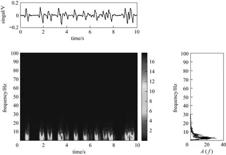
Figure 11 Typical AOK TFR of oil-in-water type slug flow (Uso=0.0118 m·s-1, Usw=0.0453 m·s-1, Usg=0.1197 m·s-1)
The oil-in-water type bubble flow can be characterized by small air bubbles and oil droplets randomly dispersed in continuous water. Due to this, the frequency spectrum of the flow pattern shows a wide frequency band (0-40 Hz) and no obvious peak. As we can see in Fig. 10, the energy distribution of oil-in-water type bubble flow in TFR is uniformly dispersed and the energy of TFR is extremely low. In addition, there is no intermittent characteristic for energy distribution in time domain, which shows the continuous presence of air bubbles and oil droplets.
For oil-in-water type slug flow, the existence of large air slugs will lead to obvious intermittent fluctuation to the conductance signal. Fig. 11 shows the AOK TFR of typical oil-in-water type slug flow, and every peak refers to a slug. As can be seen, the energy mainly concentrates at a low-frequency band (0-10 Hz) in the AOK TFR, and the TFR of the flow shows a intermittent characteristics in time domain. The low-frequency characteristics indicate that the motion of air slugs probably at low frequency band.

Figure 12 Typical AOK TFR of oil-in-water type bubble-slug transitional flow (Uso=0.0118 m·s-1, Usw=0.0453 m·s-1,Usg=0.0707 m·s-1)
The oil-in-water type bubble-slug transitional flow is the transition from bubble flow to slug flow. In this situation, the flow presents assemblage characteristics of high-frequency bubble and low-frequency slug motion, as shown in Fig. 12. Energy in the TFR mainly concentrates in a very low frequency band(0-10 Hz), which indicates energy of the flow is mainly related to slugs. Besides, there still exist some small air bubbles and/or oil droplets which will lead to small fluctuation to the signals, and the weak dispersed texture in TFR reflects the motion of the small bubbles. Moreover, in time domain, the distribution of TFR shows an obvious intermittent characteristic, indicating that this flow pattern has the characteristics of bubble and slug flows but the dominant one is the characteristics of slug flow.
3.3 Flow pattern characteristics based on total energy and main frequency
The total energy of TFR plane indicates the stationarity of the three-phase flow and it can be defined as

where (,)Ptfrepresents the TFR of the signal,Sis the time-frequency plane,tandfrepresent the time and frequency, respectively.
The main frequency of TFR represents the dominated frequency component of the fluctuating signals,and it represents the basic movement characteristic of oil-gas-water three-phase flow to a large extent. The marginal distribution of TFR can be defined as follows:whereEedgeis the marginal distribution of TFR ,Trepresents the signal length. Then the main frequencyfdis defined as the frequency which corresponds to the maximumEedgevalue.

Figure 13 shows the main frequency extraction of typical TFR for oil-in-water type bubble-slug transitional flow (Fig. 12). As we can see, the marginal distributionEedgereaches its maximum value at the first peak, and then the frequency 3.1 Hz corresponding to the maximum value can be defined as the main frequencyfd. Thus, based on Eqs. (3) and (4) we can extract the total energy and main frequency from the AOK TFR.

Figure 13 Marginal distribution of the AOK TFR (transitional flow, Uso=0.0118 m·s-1, Usw=0.0453 m·s-1, Usg=0.0707 m·s-1)
Based on these two characteristic parameters,i.e.the total energy and main frequency, we respectively constitute the plane under four different flow conditions whose flowrate of oil and water mixture is 0.83-3.33 m3·h-1, as shown in Fig. 14.

Figure 14 Flow patterns distribution on the total energy-main frequency plane with different flow rate of oil and water mixture○ oil in water type bubble flow;oil in water type bubble-slug flow; ● oil in water type slug flow
For oil-in-water type bubble flow, signal frequency can be characterized by wideband and uniform distribution. The main frequency reflects the frequency of the motion of air bubbles and oil droplets. Due to the random movement of oil droplets, the oil-in-water type bubble flows are characterized with wide main frequency distribution,i.e., in the range of 2.5-6.1 Hz.And total energy of this flow pattern is low, representing the stable flow structure in the low flow rate.
The main frequency of oil-in-water type slug flow reflects the air and liquid slug behaviors, as shown in Fig. 14. The distribution of main frequency is narrow in range of 2.8-3.8 Hz indicating the motion of the slug is singular. In addition, the total energy of oil-in-water slug flow points is far higher than that of bubble flow, which probably due to the bubbles and droplets trend to gather and become to slugs under the relatively higher velocity.
For oil-in-water type bubble-slug transitional flow, main frequency also reflects the air slug characteristics, so the distribution is narrow too, and the total energy of transitional flow lies between that of bubble flow and slug flow. The narrow distribution of main frequency and high total energy represent this flow pattern mainly possesses the characteristics of slug flow in time and frequency domain.
The results indicate that AOK TFR not only can be an efficient criterion of vertical upward oil-gas-water three-phase flow patterns identification, but also can be effectively applied to quantitatively characterize the dynamical characteristics from time-frequency domain,i.e. total energy and main frequency. However, the time-frequency cannot represent dynamical characteristic discrepancy for the same kind of flow pattern, so we in next section will use the surrogate data method to further explore the dynamic characteristics of oil-in-water type bubble and slug flows.
4 ANALYSIS OF FLOW PATTERN DYNAMICAL CHARACTERISTICS
4.1 Surrogate data method
The general process of surrogate data method is to propose the null hypothesis firstly and chose the appropriate statistic. Then, several groups of surrogate data are generated from observed time series based on the null hypothesis. Next, the original time series are tested against the null hypothesis by checking whether the discriminating statistic computed from the original time series differs significantly from the statistics computed for each of the surrogate sets. If the null hypothesis is not rejected, it shows that an observed time series actually is generated by a linear stochastic process.
The two types of null hypothesis are often applied to test nonlinearity: (1) linear auto-correlated Gaussian noise; (2) static nonlinear transform of linear Gaussian noise. To compare the data to the surrogates,a suitable discriminating statistic must be selected and it should be pivotal and independent of the way surrogates are generated. In this section, we select the time reversal asymmetry as follows:

whereτis delay time,Nis length of time series,Xiisi-th observation point; andτcan be calculated by mutual information [32].
We in this paper use the Amplitude Adjusted Fourier-transformed (AAFT) proposed by Theileret al.[16] to generate the surrogate data and the basic algorithm for this method is as follows.
(1) Generation of Gaussian distributed random numbersy(n);
(2) Thek-th value of the sorted original series is replaced with thek-th value of the sorted Gaussian data. The re-established data is now ranked like observation data and Gaussian distributed.
(3) The Fourier transform is computed fory(n),so its discrete Fourier transformation is

(4) To randomize the phases, we multiply each complex amplitude by eiφ:

whereφis independently chosen for each frequency from the interval [ ,]-π π .
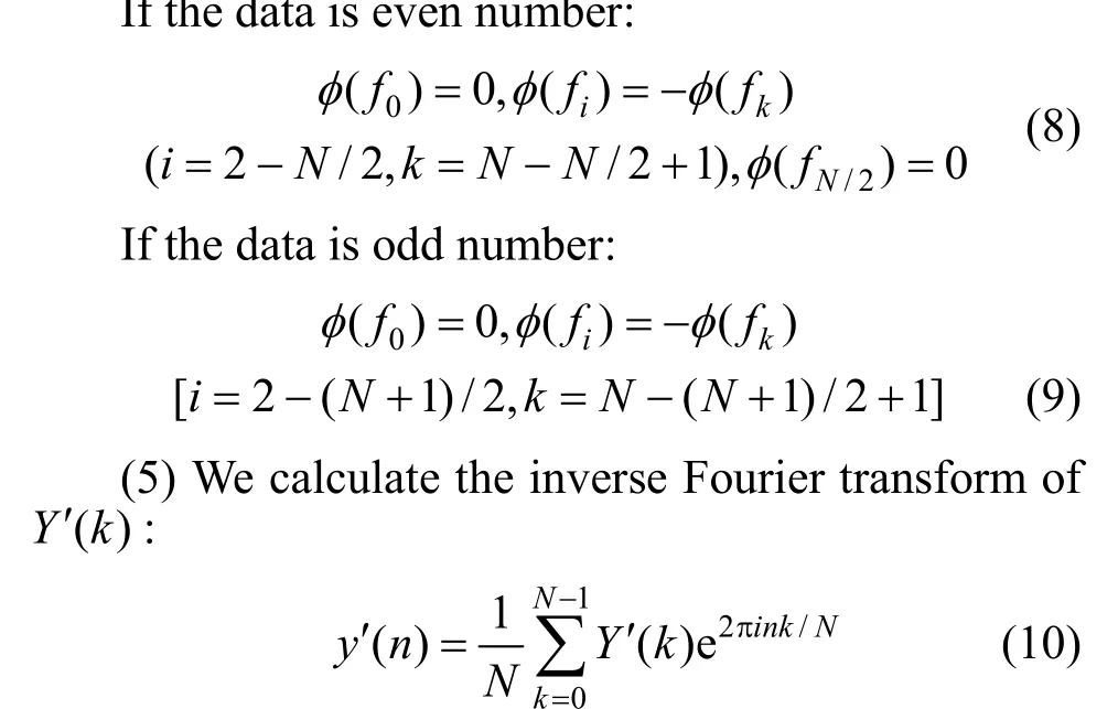
(6) Thek-th value of the sorted ()yn′ is replaced with thek-th value of the ()xn′.
Note that the original amplitude distribution is exactly maintained. The surrogate data can reflect static, monotonic nonlinerity of the original data. And the power spectrum of ()xn′ is the same as ()xn, so the linear correlation of the sequence is implicit in the process of surrogate data generated.
4.2 Investigation on flow dynamic characteristics
We use the signals measured from VMEA sensor for total 166 flow conditions including oil-in-water type bubble flow, oil-in-water type bubble-slug transitional flow and oil-in-water type slug flow. Figs. 15 and 16 are the typical surrogate data of oil-in-water type bubble and slug flows according to the null hypothesis. Compared with both of the figures, though the surrogate data having been phase randomized is different from the original data, it does not destroy the intrinsic correlation and essence of original data. So there still exists the significant difference between oil-in-water type bubble and slug flows.

Figure 15 The original signal and phase randomized signal of oil-in-water type bubble flow (Uso=0.0019 m·s-1,Usw=0.017 m·s-1, Usg=0.043 m·s-1)

Figure 16 The original signal and phase randomized signal of oil-in-water type slug flow (Uso=0.0019 m·s-1, Usw=0.017 m·s-1, Usg=0.163 m·s-1)
Figure 17 shows the variations of the time reversal asymmetry with the change of flow parameter under four different flow conditions whose flowrate of oil and water mixture is 0.83 m3·h-1, 1.67 m3·h-1, 2.5 m3·h-1and 3.33 m3·h-1, respectively. As shown in Fig. 17,the discriminating statistics of all time series are larger than 1.961 indicating that all 166 flow conditions are nonlinear.

Figure 17 The curves for the discriminating statistic of oil-in-water three-phase flow patterns with different flowrate of oil and water mixture (fo=0.1-0.5)○ oil in water type bubble flow fo=0.1; △ oil in water type bubble flow fo=0.2; □ oil in water type bubble flow fo=0.3; ☆ oil in water type bubble flow fo=0.4; ◇ oil in water type bubble flow fo=0.5;oil in water type bubble-slug flow fo=0.1;oil in water type bubble-slug flow fo=0.2;oil in water type bubble-slug flow fo=0.3;oil in water type bubble-slug flow fo=0.4;oil in water type bubble-slug flow fo=0.5; ● oil in water type slug flow fo=0.1; ▲ oil in water type slug flow fo=0.2; ■ oil in water type slug flow fo=0.3; ★ oil in water type slug flow fo=0.4; ◆ oil in water type slug flow fo=0.5
As shown in Fig. 17, under fixedfothe discriminating statistics of oil-in-water type bubble flows will tend to decrease with the increase ofUsg; in contrast,the statistics of oil-in-water type slug flows will tend to increase. It can be explained that, in oil-in-water type bubble flow, the motion trajectory of air bubbles shows intense degree of randomness because of low bubble concentration under lowUsg; but for oil-in-water type slug flow, the bubbles trend to gather and the degree of randomness for bubble motion becomes weak,so the uncertainty is reduced.
Because of short-range correlation in slug flow,their determinacy is higher than that of bubble flow.But the degree of correlation between air slug and liquid slug decreases with the increase ofUsgand the corresponding uncertainty is strengthened. The statistics of the oil-in-water type bubble-slug transitional flow lies between the values of bubble flow and slug flow, and high value and low value alternately appears,indicating that this flow has both randomness of bubble flow and short-range correlation of slug flow, but the dominant one is the characteristics of slug flow.
Moreover, the statistics of bubble flow decrease gradually with increase offounder fixed flowrate of oil and water mixture andUsg, because the distribution and motion trajectory of air bubbles become more regular due to the increase of mixture liquid equivalent viscosity induced by the increase of oil flowrate. The change offoresult in irregularly influences on the dynamic characteristic of slug flow under the sameUsg.
5 CONCLUSIONS
In summary, we investigated oil-gas-water three-phase flow in a vertical upward 125 mm ID pipe at low to moderate velocities. We firstly using Adaptive Optimal Kernel Time-Frequency Representation(AOK TFR) analyze the fluctuating signals measured from experiment and investigate the complex oil-gas-water flow behaviors in terms of joint distribution of total energy and main frequency. Our research indicates that AOK TFR methods can be effectively applied to quantitatively characterize the dynamics of different flow patterns. But the method has the limitation in discriminating dynamical characteristic difference between different flows in the same flow pattern.
To further explore the evolution of dynamical characteristics in the development of oil-in-water type bubble and slug flows, we make a nonlinearity test for oil-in-water type bubble and slug flows by using the surrogate data method. The results indicate that the discriminating statistics of oil-in-water type bubble flow will tend to decrease gradually with increase offoandUsgunder fixed flowrate of oil and water mixture,indicating that bubble flow tends to deterministic motion with the increase offoandUsg; in contrast the slug flow will turn to more complex with the increase ofUsg. Moreover, the change offowill result in irregularly influences on the slug flow. Thus, the discriminating statistics of time reversal asymmetry can effectively characterize the dynamic characteristics of oil-in-water type bubble and slug flows.
NOMENCLATURE

1 Tek, M.R., “Multiphase flow of water, oil and natural gas through vertical flow strings”,J.Pet.Tech., 10, 1029-1036 (1996).
2 Shean, A.R., “Pressure drop and phase fraction in oil-water-air vertical pipe flow”, M.S. Thesis, Massachusetts Institute of Technology,Cambridge (1976).
3 Guo, H.M., Zhou, C.D., Jin, Z.W., “An interpretative method for production logs in three-phase flows”, In: SPE Asia-Pacific Conference, Society of Petroleum Engineers, Australia, 229-235 (1991).
4 Chen, X.Z., “An investigation on the upward vertical flow characteristics of oil, gas and water in tubes”, Ph.D. Thesis, Xi’an Jiaotong University, China (1991). (in Chinese)
5 Woods, G.S., Spedding, P.L., Watterson, J.K., Raghunathan, R.S.,“Three-phase oil/water/air vertical flow”,Chemical Engineering Research and Design, 76, 571-584 (1998).
6 Zhou, Y.L., Li, H.W., Song, J.Q., Sun, B., “Chaotic characteristic analysis of image gray signals of oil-air-water three-phase flow in vertical upward pipe”,Acta Petrolei Sinica(Petroleum Processing Section), 25, 600-605 (2009).
7 Gao, Z.K., Jin, N.D., “Flow-pattern identification and nonlinear dynamics of gas-liquid two-phase flow in complex networks”,Phys.Rev.E, 79, 066303 (2009).
8 Gao, Z.K., Jin, N.D., Wang, W.X., Lai, Y.C., “Motif distributions of phase-space networks for chaotic systems and application to experimental two-phase flow patterns”,Phys.Rev.E, 82, 016210 (2010).
9 Daw, C.S., Halow, J.S., “Evaluation and control of fluidization quality through chaotic time series analysis of pressure-drop measurements”,AIChE Symposium Series, 89, 103-122 (1993).
10 Bai, B.F., Guo, L.J., Chen, X.J., “Recognition of gas-liquid two-phase flow regime based on the counter propagation network and differential pressure fluctuation”,Journal of Chemical Industry and Engineering(China), 51 (6), 848-852 (2000). (in Chinese)
11 Bai, B.F., Guo, L.J., Chen, X.J., “Nonlinear analysis on pressure fluctuation phenomena of air-water two-phase flow”,Journal of Engineering Thermophysics, 22, 359-362 (2001). (in Chinese)
12 Jin, N.D., Wang, W.W., Ren, Y.Y., Zhong, X.F., Tian, S.X., “Fractal and chaotic characteristics of oil-gas-water three phase bubble flow pattern”,Chinese Journal of Geophysics, 44, 266-274 (2001). (in Chinese)
13 Hu, Z.H., Yang, Y.H., Liu, L., Zhou, F.D., “Local flow regime transition criteria of gas-liquid two-phase flow in vertical upward tube with a horizontal rod”,Chin.J.Chen.Eng., 14 (2), 442-449 (2006).
14 Li, H.W., Zhou, Y.L., Sun, B., Yang, Y., “Multi-scale chaotic analysis of the characteristics of gas-liquid two-phase flow patterns”,Chin.J.Chen.Eng., 18 (5), 880-888 (2010).
15 Wang, Z.Y., Jin, N.D., Gao, Z.K., Zong, B., Wang, T., “Nonlinear dynamical analysis of large diameter vertical upward oil-gas-water three-phase flow pattern characteristics”,Chem.Eng.Sci., 65, 5226-5236 (2010).
16 Theiler, J., Eubank, S., Longtin, A., Galdrikian, B., Farmer, J.D.,“Testing for nonlinearity in time series: The method of surrogate data”,Physica D, 58, 77-94 (1992).
17 Dolan, K.T., Neiman, A., “Surrogate analysis of coherent multichannel data”,Phys.Rev.E, 65, 026108 (2002).
18 Nakamura, T., Small, M., “Small-shuffle surrogate data: Testing for dynamics in fluctuating data with trends”,Phys.Rev.E, 72, 056216(2005).
19 Pritchard, W.S., Duke, D.W., Krieble, K., “Dimensional analysis of resting human EEG II: Surrogate-data testing indicates nonlinearity but not low-dimensional chaos”,Psychophysiology, 32, 486-491(1995).
20 Fell, J., Roschke, J., Schaffner, C., “Surrogate data analysis of sleep electroencephalograms reveals evidence for nonlinearity”,Biol.Cyber., 75, 85-92 (1996).
21 Lin, H.Y., Chen, W., Tsutsumi, A., “Surrogate testing for nonlinear hydrodynamics in bubble columns”,Ind.Eng.Chem.Res., 46,1632-1641 (2007).
22 Zong, Y.B., Jin, N.D., Wang, Z.Y., Gao, Z.K, Wang, C., “Nonlinear dynamic analysis of large diameter inclined oil-water two phase flow pattern”,Int.J.Multiphase Flow, 36 (3), 166-183 (2010).
23 Gao, Z.K., Jin, N.D., “Nonlinear characterization of oil-gas-water three-phase flow in complex networks”,Chem.Eng.Sci., 66 (12),2660-2671 (2011).
24 Nuland, S., Skarsvag, K., Seether, G., Fuchs, P., “Phase fractions in three-phase gas-oil-water flow”, In: Proc. 5th Int. Conf. on Multiphase Prod., Burns, A.P., ed., Elsevier Applied Science, Cannes, France,3-30 (1991).
25 Herm-Stpelberg, H., Mews, D., “Pressure-drop calculation in three-phase slug flow of water, oil and air”,Int.Chem,Eng., 34 (3),295-314 (1994).
26 Hervieu, E., Seleghim, P. Jr., “An objective indicator for two-phase flow pattern transition”,Nucl.Eng.Design, 184, 421-435 (1998).
27 Jana, A.K., Das, G., Das, P.K., “Flow regime identification of two-phase liquid-liquid upflow through vertical pipe”,Chem.Eng.Sci., 61 (5), 1500-1515 (2006).
28 Chakrabarti, D.P., Das, G., “The transition from water continuous to oil continuous flow pattern”,AIChE J., 52 (11), 3668-3678 (2006).
29 Nguyen, V.T., Euh, D.J., Song, C.H., “An application of the wavelet analysis technique for the objective discrimination of two-phase flow patterns”,Int.J.Multiphase Flow, 36, 755-768 (2010).
30 Jones, D.L., Baraniuk, R.G., “An adaptive optimal-kernel timefrequency representation”,IEEE Trans.Signal Processing, 43 (10),2361-2371 (1995).
31 Sun, B., Wang, E.P., Ding, Y., Bai, H.Z., Huang, Y.M., “Time-frequency signal processing for gas-liquid two phase flow through a horizontal venturi based on adaptive optimal-kernel theory”,Chin.J.Chen.Eng., 19 (2), 243-252 (2011).
32 Fraster, A.M., Swinney, H.L., “Independent coordinates for strange attractors from mutual information”,Phys.Rev.A, 33, 1134-1140(1986).
猜你喜欢
杂志排行

Chinese Journal of Chemical Engineering的其它文章
- Ammoximation of Cyclohexanone to Cyclohexanone Oxime Catalyzed by Titanium Silicalite-1 Zeolite in Three-phase System*
- Adsorption and Desorption of Praseodymium (III) from Aqueous Solution Using D72 Resin*
- Turbulent Characteristic of Liquid Around a Chain of Bubbles in Non-Newtonian Fluid*
- Isolation and Characterization of Heterotrophic Nitrifying Strain W1*
- Recovery of Tungsten (VI) from Aqueous Solutions by Complexationultrafiltration Process with the Help of Polyquaternium*
- Optimizing the Chemical Compositions of Protective Agents for Freeze-drying Bifidobacterium longum BIOMA 5920*