An Experimental Study of Liquid-Liquid Microflow Pattern Maps Accompanied with Mass Transfer*
2012-03-22SHAOHuawei邵华伟Yangcheng吕阳成WANGKai王凯andLUOGuangsheng骆广生
SHAO Huawei (邵华伟), LÜ Yangcheng (吕阳成), WANG Kai (王凯) and LUO Guangsheng(骆广生)**
State Key Laboratory of Chemical Engineering, Department of Chemical Engineering, Tsinghua University, Beijing 100084, China
1 INTRODUCTION
Liquid-liquid systems have been extensively mentioned in many industrial processes. Microfluidic technology has demonstrated its advantages in liquid-liquid dispersion processes [1-5] with respect to mass transfer efficiency [1-3], safety, repeatability and controllability [4, 5]. The microfluidic devices with various configurations, mainly including T-shaped microchannels [6, 7], co-flowing pipes [8-13], hydrodynamic flow-focusing microchannels [14, 15], geometrically mediated break up microchannels [16], have been developed and applied in liquid-liquid and gas-liquid microdispersion processes [17-22].
Many groups have paid their attention to liquidliquid microflow in microchannels [23-25]. One of the most frequently used microfluidic geometries is a co-flowing coaxial structure in which one liquid is forced through an orifice into a continuous fluid to form droplets (dripping flow) or jet (jetting flow). In the dripping flow region monodispersed droplets can be generated at the needle tip under the balance of the viscous force and surface tension force [10, 11, 26]. So the droplet formation can be used to measure the interfacial tension [26]. While in jetting flow region, the viscous force or inertia force is dominant, and the inner liquid firstly forms an extended jet from the tip and then breaks up downstream due to the Rayleigh-Plateau instability [8, 9, 11].
There are many publications about liquid-liquid microdispersion processes, but few of them involve with mass transfer. In order to understand more fundamentals of liquid-liquid microflow in microdevices and apply it in practice, we investigate the liquid-liquid microflows with mass transfer in a co-axial microfluidic device in this study. Three working systems including n-butanol + phosphoric acid (PA) + water, methyl isobutyl ketone (MIBK) + PA + water, 30% kerosene in tri-n-butylphosphate (TBP) + PA + water were selected. The influence of mass transfer direction and intensity on liquid-liquid microflow was experimentally studied. The new liquid-liquid microflow pattern and phenomena were observed, and the liquid-liquid micro dispersion mechanism with mass transfer was discussed.
2 EXPERIMENTAL
2.1 Microfluidic device
Figure 1 shows the experimental setup. The experiments were performed in a coaxial microfluidic device fabricated on a 30 mm×20 mm×3 mm polymethylmetacrylate (PMMA) plate using an end mill.The microdevice, as shown in Fig. 1, consisted of a glass capillary produced by West China Center of Medical Sciences, Sichuan University and a stainless steel needle embedded into the PMMA substrate. The inner and outer diameters of the glass capillary were approximately 720 μm and 920 μm, respectively. The inner and outer diameters of the needle were approximately 160 μm and 300 μm, respectively. The needle was inserted 10 mm into the glass capillary and fixed carefully to ensure it to be coaxial with the capillary. The microfluidic device was sealed using another PMMA plate of 1 mm thickness with supersonic assisted sealing technique [27]. Three microsyringe pumps were used to pump feeds into the microfluidic device.

Figure 1 The experimental setup
2.2 Liquid-liquid working systems
n-Butanol + PA + water, MIBK + PA + water,30% kerosene in TBP + PA + water were used as the working systems. The liquid-liquid interfacial tensions of these three systems are listed in Table 1.
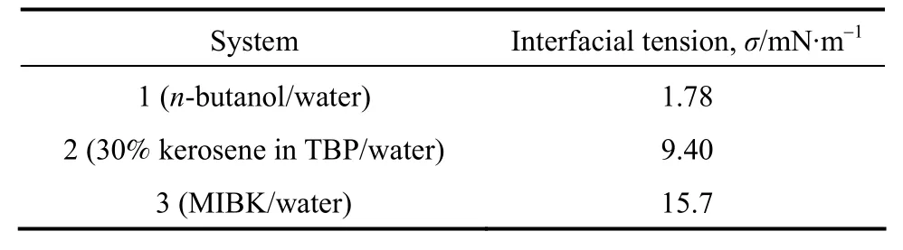
Table 1 The interfacial tensions of working systems (25 °C)
n-Butanol, MIBK and 30% kerosene in TBP were mutually saturated with water before used, respectively. According to the mass transfer direction of PA,the experimental systems are classified into 2 types.For type 1, the mass transfer direction is from the aqueous phase to the organic phase with PA added in the aqueous phase. For type 2, the mass transfer direction is from the organic phase to the aqueous phase with PA added in the organics phase. In all experiments,the aqueous phase was used as the continuous phase,and the organic phase was used as the dispersed phase.The viscosities of the continuous phase with different PA concentration at 25 °C are listed in Table 2.
2.3 Visualization and analysis
Experiments were carried out under observations by a microscope at the magnification of 100. Ahigh-speed CCD video camera was connected to the microscope and the images were recorded with a frequency of 100 images per second. The flow was judged to belong to a jetting flow pattern when the length of the jet was larger than two times of the droplet diameter. The typical flow patterns are shown in Fig. 2.

Table 2 Viscosities of PA solutions

Figure 2 Typical photos of different flow patterns (The working system was n-butanol + PA + water)
The concentration of phosphoric acid in water or in the organic phase was measured by titration. The viscosities of different PA concentration solutions(Table 2) and the interfacial tension of the blank systems (Table 1) were measured using the spinning digital viscometer (NDJ-5S, Shanghai Jingtian Electronics Instrument Co.) and the commercial interfacial tensiometry (OCAH200, Data Physics Instruments GmbH) at 25 °C.
3 RESULTS AND DISCUSSION
3.1 New liquid-liquid microflow patterns with mass transfer
Some specific liquid-liquid flow patterns were observed when mass transfer happening in the liquidliquid microdispersion processes using the system ofn-butanol + PA + water as the model system.
When PA transferred from the organic phase(dispersed phase) to the aqueous phase (continuous phase), numerous tiny aqueous droplets in the organic phase were observed and a double emulsion W/O/W microflow in a single dispersion process was formed in some cases. Fig. 3 shows some typical moments of the liquid-liquid microdispersion process with the PA mass concentration in the organic phaseat 9%.Some tiny droplets were firstly found att=0.8 s. As time elapses, more and more tiny droplets were found and larger droplets emerged subsequently. The pathlines of these tiny droplets could express the flow field inside the organic droplet at the forming stage very well.
The possible reasons to provoke the tiny droplets are the Marangoni effect or local phase separation.is 9%. It indicates that the prerequisite for forming the double-emulsion microflow is the quick and substantive mass transfer of PA from the organic phase to the aqueous phase. However, the concentration of water in the oil phase should be close to saturation. The closed region of double-emulsion microflow shown in Fig. 4 is because that when the flow rate of the dispersed phase (Qd) is larger than 5 μl·min-1, the organic droplet forming time is short and the net mass transfer is not enough to induce the phase separation; whenQdis lower than 0.5 μl·min-1, the weakness of the inner circular flow results in lower mass transfer in the organic phase; when the flow rate of the continuous phase (Qc) is larger than 300 μl·min-1, the mass transfer time at the droplet forming stage is too short; whenQcis lower than 11 μl·min-1, the overall mass transfer rate is low. Therefore we may conclude that a certain amount of PA transferred from the organic phase to Since no obvious interface turbulence was observed from the movies, the latter one seems to be more reasonable. The strong inner circular flow can enhance the mass transfer at the droplet forming stage effectively. Once the concentration of PA in the organic phase decreases due to mass transfer, the surplus water dissolved with PA addition may separate out and form tiny aqueous droplet. The amount of this part of water will increase with mass transfer proceeding, resulting in the growth of aqueous droplets. However, the coalescence also makes aqueous droplets grow up. Finally the double emulsion of W/O/W flow can form when the dispersed phase droplet breaks away from the tip of the needle. We define this flow as the double-emulsion microflow.

Figure 3 A typical formation process of double-emulsion microflow at=9%, Qc=160 μl·min-1, Qd=1 μl·min-1 (The working system was n-butanol + PA + water)

Figure 4 The operation region for double-emulsion microflows at =9%
Figure 4 presents the operation region of the double-emulsion microflow When the aqueous phase is basically required for the formation of double-emulsion microflow when the organic phase is used as the dispersed phase. When PA transferred from the aqueous phase to the organic phase with the system, the double-emulsion microflow did not appear in our experiments.
The formation of double-emulsion flow shows that water dissolved in the organic phase may have distinct effect on the flow pattern. To further understand the mechanism of the microflows, we increased the PA concentration and decreased the water concentration in the organic phase. Fig. 5 shows the experimental results. When the PA concentration was much higher, clear waves were generated at the interface,indicating more violent turbulent caused by higher mass transfer rate. At higherQc, part of organic phase was even thrown out from the highly unstable interface and formed tails following the droplet, as shown in Fig. 6. This microflow is mainly caused by the Marangoni effect, which could be applied to explore the surface tension sensitivity to the solute concentration variation effectively.


3.2 Effect of mass transfer on liquid-liquid two-phase flow pattern
The above new liquid-liquid microflow phenomena indicate that the mass transfer of PA can influence the interfacial behavior, including the liquid-liquid interfacial tension and interface turbulence,which heavily affects the two-phase microflow. In this section, we used the three working systems with different interfacial tension to study further the effect of mass transfer on two-phase microflows.
In the coaxial capillary microfluidic device, the droplet formation process was mainly affected by the two phase flow rates, fluid viscosity and interfacial tension. Two different droplet formation mechanisms were distinguished: (1) Dripping flow region, the droplets are formed at the place close to the capillary tip; (2) Jetting flow region, the droplets break up from an expanded liquid jet. The droplet dispersion scale depends directly on the break up mechanism. Crameret al. [10] found that the tendency of the disperse phase to generate a liquid jet rises with increasing velocity of the continuous disperse phase, higher flow rate and viscosity of the disperse phase and lower interfacial tension. Utadaet al. [11] observed two distinct classes of transitions from dripping to jetting, and unified them by considering the balance of inertial forces, viscous force and surface tension exerted on the droplet. The continuous phaseCaand the dispersed phaseWewere used to characterize the balance of inertial forces, viscous force and surface tension and distinguish the different flow patterns.CacandWedare defined respectively as
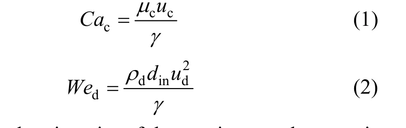
whereμcis the viscosity of the continuous phase,ρdis the density of the dispersed phase,ucandudare the velocities of the continuous phase and dispersed phase,respectively,dinis the inner diameter of the needle,γis the liquid liquid interfacial tension.

Figure 7 shows the flow patterns of n-butanol +PA + water system with different initial PA concentration in the aqueous phase () at various two-phase flow rates. It clearly shows that the increase ofcan expand the jetting flow region. Whenis zero(no mass transfer during the dispersion process), as shown in Fig. 7 (a), the dripping flow region is large.But whenis 40%, as shown in Fig. 7 (e), dripping flow is hardly to be formed. Whenis small (less than 30%), a horizontal line can be drawn out at low Ca number. This horizontal line reveals that the inertial forces should be balanced with surface tension at low viscous force. When We is small, the surface tension dominates the microdispersion process, leading the microflow to dripping flow. At higher Ca, a slantwise line could be drawn, meaning that both the inertial force and the viscous force play important roles in the microdispersion process. Asincreases, the horizontal line and the slantwise line shift to the original point and finally horizontal line disappears whenis 40%. From the force balance at dripping flow region boundary, we can know that the reason of the change of flow region is mainly due to the reduction of surface tension by mass transfer.
The effect of mass transfer from the organic phase to the aqueous phase was also studied. The similar changes were found. Fig. 8 shows the experimental results, indicating that the increase of PA con-centration in the organic phase () can expand the jetting flow region, too.
In general, regardless of adding PA in the aqueous phase or the organic phase, the transition region from the dripping flow to the jetting flow shifts to lower two-phase flow rates. This trend can be explained from the changes of viscosity of the continuous phase, density of the dispersed phase, and interfacial tension. Obviously with the addition of PA in the systems, the viscosity and density of corresponding fluid are increased. And the interfacial tension is decreased. So the liquid-liquid microflow tends to the jetting flow region.
The expansion of jetting flow region by mass transfer was also observed with 30% kerosene in TBP+ PA + water as the system as shown in Figs. 9 and 10. The borderlines of dripping region and jetting region shift to low We and Ca due to mass transfer. Different from n-butanol + PA + water system, in 30%kerosene in TBP + PA + water system the displacement of the dripping and jetting region borderline is larger even at low PA concentration. It may be because of the difference of the liquid-liquid interfacial tension between the two systems. In low interfacial tension system, as n-butanol + PA + water system, the influence of mass transfer on interfacial tension is significant only at large concentration gradient, while for medium interfacial tension system, as 30% kerosene in TBP + PA + water system, the interfacial tension
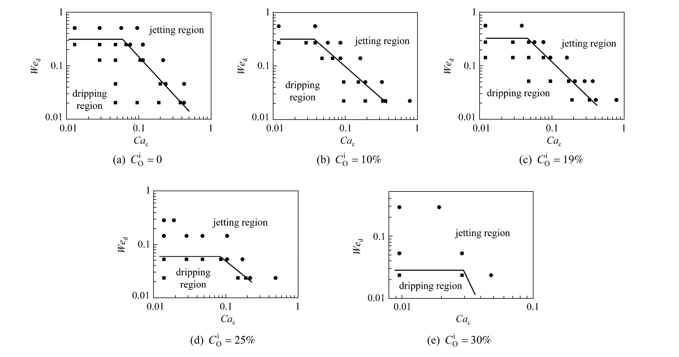
Figure 8 The flow pattern maps of n-butanol + PA + water system with mass transfer from the organic phase to the aqueous phase● jetting flow; ■ dripping flow

Figure 9 The flow pattern maps of 30% kerosene in TBP + PA + water system with mass transfer from the aqueous phase to the organic phase● jetting flow; ■ dripping flow
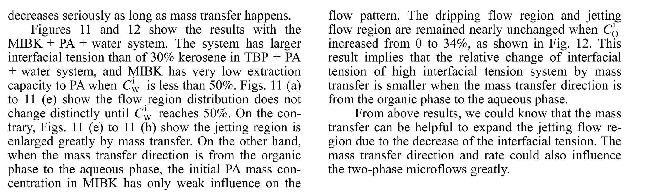

Figure 10 The flow pattern maps of 30% kerosene in TBP + PA +water system with mass transfer from the organic phase to the aqueous phase● jetting flow; ■ dripping flow
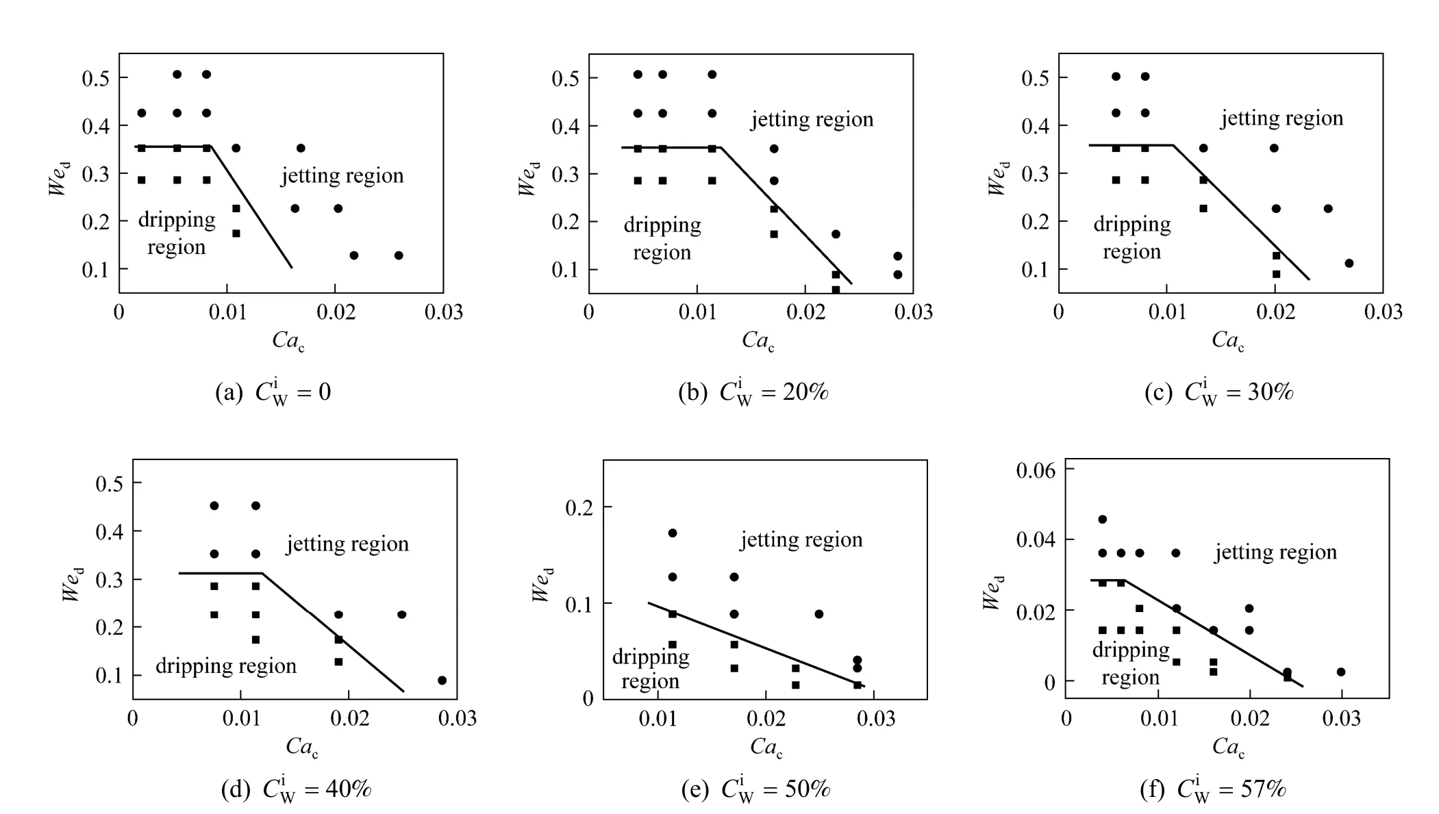
Figure 11 The flow pattern maps of MIBK + PA + water system with mass transfer from the aqueous phase to the organic phase● jetting flow; ■ dripping flow

Figure 11 The flow pattern maps of MIBK + PA + water system with mass transfer from the aqueous phase to the organic phase● jetting flow; ■ dripping flow
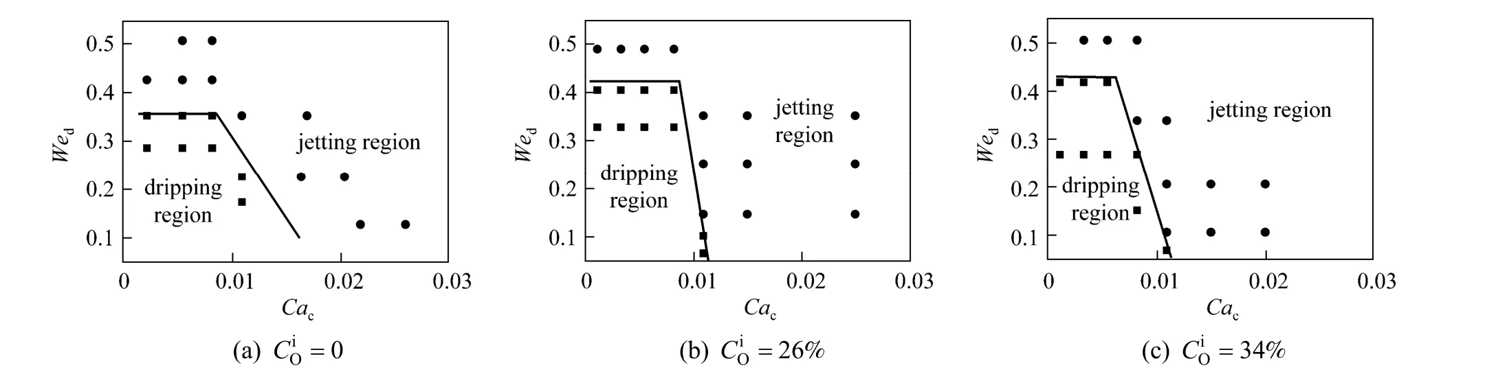
Figure 12 The flow pattern maps of MIBK + PA + water system with mass transfer from the organic phase to the aqueous phase● jetting flow; ■ dripping flow
4 CONCLUSIONS
In this work we presented the experimental results of liquid-liquid microflow in a coaxial circular microfluidic device with mass transfer. Three working systems with typical and various interfacial tension were used. Liquid-liquid flow patterns were observed when the mass transfer happened in the microdispersion processes. When PA transferred from the organic phase to the aqueous phase, numerous tiny aqueous droplets in the organic phase were generated and a double emulsion W/O/W microflow in a single dispersion process was formed in some experimental conditions. The formation of double-emulsion requires that the net transfer of PA from the organic phase to the aqueous phase is quick and substantive, corresponding to high mass transfer efficiency in droplet generation stage and a close window of two-phase flow rates. The tiny droplets are of potential tracer to reflect on the inner circular flow in droplet generation stage. When the PA concentration was much higher,violent Marangoni effect could be observed. Waves were observed clearly at the interface. At higherQc,part of organic phase even was thrown out from the highly unstable interface and formed tails following the droplet. To get a clear known of the liquid-liquid microdispersion process,Wednumber of the dispersed phase andCacnumber of the continuous phase were used to distinguish the flow region with different mass transfer direction and intensity. The transition region from dripping flow to jetting flow shifted to lower two-phase flow rates as PA transfer was introduced.
The mutual influence of mass transfer and liquidliquid dispersion is worth for further investigation. A quantitative relationship of the mass transfer intensity during droplet formation stage and the droplet dispersion performance is unclear. More research is needed on the mechanism of microflow and mass transfer in microchannels.
1 Xu, J.H., Tan, J., Li, S.W., Luo, G.S., “Enhancement of mass transfer performance of liquid-liquid system by droplet flow in microchannels”,Chem.Eng.J., 141 (1-3), 242-249 (2008).
2 Dessimoz, A.L., Cavin, L., Renken, A., Kiwi-Minsker, L., “Liquid-liquid two-phase flow patterns and mass transfer characteristics in rectangular glass microreactors”,Chem.Eng.Sci., 63 (16),4035-4044 (2008).
3 Shrivastava, A., Cussler, E.L., Kumar S, “Mass transfer enhancement due to a soft elastic boundary”,Chem.Eng.Sci., 63 (17),4302-4305 (2008).
4 Jensen, K., Lee, A., “The science & applications of droplets in microfluidic devices—Foreword”,Lab Chip, 4 (4), 31-32 (2004).
5 Xu, J.H., Li, S.W., Tan, J., Wang, Y.J., Luo, G.S., “Preparation of highly monodisperse droplet in a T-junction microfluidic device”,AIChE J., 52 (9), 3005-3010 (2006).
6 Nisisako, T., Torii, T., Higuchi, T., “Droplet formation in a microchannel network”, Lab Chip, 2 (1), 24-26 (2002).
7 Xu, J.H., Li, S.W., Tan, J., Luo, G.S., “Correlations of droplet formation in T-junction microfluidic devices: from squeezing to dripping”,Microfluid. Nanofluid., 5 (6), 711-717 (2008).
8 Guillot, P., Colin, A., Utada, A.S., Ajdari, A., “Stability of a jet in confined pressure-driven biphasic flows at low reynolds numbers”,Phys. Rev. Lett., 99, 104502 (2007).
9 Guillot, P., Ajdari, A., Goyon, J., Joanicot, M., Colin, A., “Droplets and jets in microfluidic devices”, Comptes Rendus Chimie, 12 (1-2),247-257 (2009).
10 Cramer, C., Fischer, P., Windhab, E.J., “Drop formation in a co-flowing ambient fluid”, Chem. Eng. Sci., 59 (15), 3045-3058(2004).
11 Utada, A.S., Fernandez-Nieves, A., Stone, H.A., Weitz, D.A., “Dripping to jetting transitions in coflowing liquid streams”, Phys. Rev.Lett., 99, 094502/1 (2007).
12 Chu, L.Y., Utada, A.S., Shah, R.K., Kim, J.W., Weitz, D.A., “Controllable monodisperse multiple emulsions”, Ang. Chem. Int. Ed., 46(47), 8970-8974 (2007).
13 Lan, W.J., Li, S.W., Xu, J.H., Luo, G.S., “Rapid measurement of fluid viscosity using co-flowing in a co-axial microfluidic device”,Microfluid. Nanofluid., 8 (5), 687-693 (2010).
14 Wang, W.H., Zhang, Z.L., Xie, Y.N., Wang, L., Yi, S., Liu, K., Liu, J.,Pang, D.W., Zhao, X.Z., “Flow-focusing generation of monodisperse water droplets wrapped by ionic liquid on microfluidic chips: from plug to sphere”, Langmuir, 23 (23), 11924-11931 (2007).
15 Xu, Q.Y., Nakajima, M., “The generation of highly monodisperse droplets through the break up of hydrodynamically focused microthread in a microfluidic device”, Appl. Phys. Lett., 85 (17),3726-3728 (2004).
16 Jullien, M.C., Ching, M., Cohen, C., Menetrier, L., Tabeling, P.,“Droplet break up in microfluidic T-junctions at small capillary numbers”, Phys. Fluids, 21, 072001 (2009).
17 Shui, L., Eijkel, J., van den Berg A, “Multiphase flow in microfluidic systems - Control and applications of droplets and interfaces”,Adv. Colloid Interface Sci., 133 (1), 35-49 (2007).
18 Benz, K., Jackel, K.P., Regenauer, K.J., Schiewe, J., Drese, K., Ehrfeld, W., Hessel, V., Lowe, H., “Utilization of micromixers for extraction processes”, Chem. Eng. Technol., 24 (1), 11-17 (2001).
19 Kralj, J.G., Sahoo, H.R., Jensen, K.F., “Integrated continuous microfluidic liquid-liquid extraction”, Lab Chip, 7 (2), 256-263 (2007).
20 Ueno, M., Hisamoto, H., Kitamori, T., Kobayashi, S.,“Phase-transfer alkylation reactions using microreactors”, Chem.Commun., (8), 936-937 (2003).
21 Burns, J.R., Ramshaw, C., “The intensification of rapid reactions in multiphase systems using slug flow in capillaries”, Lab Chip, 1 (1),10-15 (2001).
22 Mary, P., Studer, V., Tabeling, P., “Microfluidic droplet-based liquid-liquid extraction”, Anal. Chem., 80 (8), 2680-2687 (2008).
23 Hudson, S.D., “Poiseuille flow and drop circulation in microchannels”, Rheol. Acta, 49 (3), 237-243 (2010).
24 Wang, H., Wang, Y., “Flow in microchannels with rough walls: flow pattern and pressure drop”, J. Micromech. Microeng., 17 (3), 586-596(2007).
25 Zhao, Y.C., Chen, G.W., Yuan, Q., “Liquid-liquid two-phase flow patterns in a rectangular microchannel”, AIChE J., 52 (12), 4052-4060(2006).
26 Xu, J.H., Li, S.W., Lan, W.J., Luo, G.S., “Microfluidic approach for rapid interfacial tension measurement”, Langmuir, 24 (19), 11287-11292(2008).
27 Li, S.W., Xu, J.H., Wang, Y.J., Lu, Y.C., Luo, G.S., “Low-temperature bonding of poly-(methyl methacrylate) microfluidic devices under an ultrasonic field”, J. Micromech. Microeng., 19, 015035 (2009).
猜你喜欢
杂志排行

Chinese Journal of Chemical Engineering的其它文章
- Retrospect and Perspective of Micro-mixing Studies in Stirred Tanks*
- In-situ Synthesis and Catalytic Properties of ZSM-5/Rectorite Composites as Propylene Boosting Additive in FluidCatalytic Cracking Process*
- Low-temperature Electrodeposition of Aluminium from Lewis Acidic 1-Allyl-3-methylimidazolium Chloroaluminate Ionic Liquids*
- Solvent Extraction of Yttrium by Task-specific Ionic Liquids Bearing Carboxylic Group*
- Liquid-Liquid-Liquid Three Phase Extraction Apparatus: Operation Strategy and Influences on Mass Transfer Efficiency*
- Micron-sized Magnetic Polymer Microspheres for Adsorption and Separation of Cr(VI) from Aqueous Solution*