Liquid-Liquid-Liquid Three Phase Extraction Apparatus: Operation Strategy and Influences on Mass Transfer Efficiency*
2012-03-22HEXiuqiong何秀琼HUANGKun黄昆YUPinhua于品华ZHANGChao张超XIEKeng谢铿LIPengfei李鹏飞WANGJuan王娟ANZhentao安震涛andLIUHuizhou刘会洲
HE Xiuqiong (何秀琼), HUANG Kun (黄昆)**, YU Pinhua (于品华), ZHANG Chao(张超), XIE Keng (谢铿), LI Pengfei (李鹏飞), WANG Juan (王娟), AN Zhentao(安震涛) and LIU Huizhou (刘会洲)**
1 Key Laboratory of Green Process and Engineering, Institute of Process Engineering, Chinese Academy of Sciences, Beijing 100190, China
2 Graduate University of Chinese Academy of Sciences, Beijing 100049, China
1 INTRODUCTION
Three-liquid-phase extraction (TLPE) is a new technique developed in recent years for separation of multi-component mixtures [1, 2]. This technique takes advantage of the differences in physicochemical properties of three coexisted phases to achieve multi-phase liquid separation of two or more components in one-step extraction, which provides a variety of possibilities for improvement of liquid extraction processes [3]. The conventional liquid-liquid two-phase extraction (solvent extraction), composed of an organic phase and an aqueous phase, requires a great many steps to separate multi-component system, and each step extraction obtains only one target compound [4-7]. Previous works found that a stable coexisted three-layered liquid system consisted of an organic phase and two polymerbased aqueous phases, was attainable, and each phase enriched different components selectively [8, 9].Therefore, TLPE is in fact a process combining the traditional organic-water solvent extraction and polymer-based aqueous biphasic extraction. It enables an extraction process to be conducted in mild environment like aqueous two-phase extraction [10-12], and it is also efficient and easy to be operated continuously on industrial scale to enjoy the features of conventional liquid-liquid extraction.
Many potential applications of TLPE have been reported, including purifying and/or separating biochemicals, environmental wastewaters treatment, extracting of natural products, dealing with multi-metal leaching solutions and preparation of ultrafine powder[13-20]. These works advance TLPE gradually to its technical maturity. However, no industrial scale applications have been reported until now due to the difficulties in designing appropriate industrial-aimed equipments for conducting countercurrent and continuous TLPE processes. Traditionally, the solvent extraction apparatus includes three types, mixer-settler, extraction column (or tower) and centrifugal extractor. These equipments aim mainly to meet the requirements of liquid-liquid two-phase separation and mass transfer[21]. Centrifugal extractor [22] separates the light phase and heavy phase using centrifugal force. However, it is difficult to control the TLPE process to separate three liquid phases individually only by centrifugal force. Extraction column [23, 24] and mixer-settler separate two immiscible phases by force of gravity based on their density differences. However, most extraction columns are continuous-contacting equipments. Two liquid phases contact with each other in the cascade of continuous counter-current flow and don’t reach equilibrium state. Therefore, it is difficult for an extraction column to meet the phase-forming behavior of a three-liquid-phase system (TLPS) and to control the interphase mass transfer of different components. Mixer-settler is a kind of step-by-step contacting equipment. Two liquid phases mix in the mixer,and flow into the followed settler for phase separating.Each mixer-settler completes an extraction cycle.However, two-chamber multi-stage mixer-settler is difficult to be operated in a TLPE process due to the difficulties of separating three individual liquid phases flowing out of the extractor and directs them to subsequent counter-current operation.
In present work, we propose a mixer-settler-mixer three chamber integrated extraction unit for that purpose. A model TLPS used here is nonane (organic top-phase)-polyethylene glycol (PEG 2000) (polymer middle-phase)-(NH4)2SO4aqueous solution (aqueous bottom-phase) for the simultaneous extraction and separation of two phenolic isomers, p-nitrophenol(p-NP) and o-nitrophenol (o-NP) [21]. The effects of the structural design of TLPE apparatus and some of its key operational parameters on three-liquid-phase mass transfer of two phenols are investigated. The present work provides a feasible approach of scaling up the proposed three-liquid-phase extraction apparatus to future industrial applications.
2 EXPERIMENTAL
2.1 Chemicals and preparation
Analytical grade of o-nitrophenol (o-NP) and p-nitrophenol (p-NP) were purchased from Sinopharm Chemical Reagent Co. The stock feed-in aqueous solution of o-NP and p-NP was prepared by dissolving solid nitrophenols into distilled water. The concentrations of two phenols in distilled water were both about 1 g·L-1respectively. Polyethylene glycol (chemical grade,with average molecular mass of 2000) and (NH4)2SO4(A.R.), both from Sinopharm Chemical Reagent Co.,were used to prepare their stock aqueous solutions with mass percent of 50% and 40% in water, respectively. Nonane (A.R.) from Sinopharm Chemical Reagent Co. was chosen as the organic extractant. NaOH(A.R.) from Xilong Chemical Engineering Incorporated Co. and H2SO4(A.R.) from Beijing Chemical Co.were used to adjust pH values of the stock aqueous solutions to 4. Methanol (C.P.), which was obtained from Tianjin Xihua Reagent Factory, was used to dilute organic samples and as mobile phase of RP-HPLC.
2.2 Methods and procedures
As for the framework design of a TLPE processing unit, three continuous steps must be considered:Firstly, a stable aqueous biphasic system should be obtained by mixing polymer aqueous solutions with a certain amount of salt; Then, the resultant polymer based aqueous two phases contact with a non-polar organic solvent to form a three-liquid phases system to partition the objective components; Finally, the organic top phase must be separated again from the aqueous two phases after three-phase settling for subsequently continuous phase contacting. In the present work, we use separate beakers to simulate the extraction processes in three individual chambers of the proposed TLPE extractor: the three-phase mixer, the three-phase settler and the two-phase mixer, respectively.By doing so, we can avoid the mutual interferences among the three chambers and the influences from three-phase liquid flow. Therefore, the research targets were simplified. The beaker has a volume of 300 ml with inner diameter of 68 mm, into which 70 ml of phenol-containing solutions were added each time. An anchor impeller, with diameter of 54 mm and height of 38 mm, was fixed in the beaker to mix the three liquid phases.
All experiments were conducted at room temperature. Firstly, the required volumes of the feed-in aqueous solution containing phenols, the stock solutions of PEG 2000 and (NH4)2SO4were mixed in the glass beaker. Then nonane was added into and mixed with the resultant aqueous biphasic solutions. After that, the mixture was settled for clear phase separation.A stable three-liquid-phase coexisted system can be obtained. The top is organic nonane phase, the middle is PEG-rich phase and the bottom is (NH4)2SO4aqueous phase. Samples taken from three-layered liquid phases, respectively, were diluted with methanol (dilute nonane phase samples) and distilled water (dilute PEG phase and aqueous phase samples) to appropriate concentrations for subsequent high performance liquid chromatography (HPLC) analysis.
2.3 Analysis
Samples taken from each phase after extraction were analyzed by high performance liquid chromatography (RP-HPLC, Agilent Technology, USA) with UV detector at 276 nm. External standard method was used to determine concentrations of two phenols in each phase. A chromatographic column (C18, length:250 mm, I.D.: 4.6 mm, partical size: 5 μm, Agilent Technology, USA) was used. Samples (10 μl) were loaded by mobile phase composed of 75% methanol and 25% ultra-pure water (volume percentage) at a flow rate of 0.6 ml·min-1
Mass percentage was used to express the extraction results, and the mass percentage of o-NP and p-NP in three phases are described as
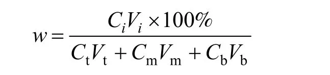
where Ciis the concentration of o-NP or p-NP in one of three phases, and Viis the volume of one phase. Ct,Cmand Cbrepresent the concentration of o-NP or p-NP in the top, middle and bottom phase, respectively. Vt, Vmand Vbdescribe the volume of the top,middle and bottom phase, respectively.
3 RESULTS AND DISCUSSION
3.1 Description of the three-liquid-phase extractor
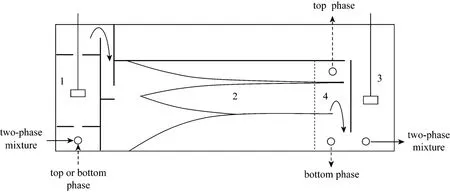
Figure 1 Sketch structure of the proposed three-liquid-phase extractor
Figure 1 shows the sketch structure of the mixer-settler-mixer three chamber integrated extractor for TLPE. The extractor is composed of a three-phase mixer (A), a three-phase settler (B), a two-phase mixer(C) and a liquid-flow control zone (D) at the end of the three-phase settler. This extraction equipment is based on the conventional mixer-settler but with an additional two-phase mixer following the phase settler.The aim to design the three chamber integrated extractor lies in two aspects (1) to achieve the purpose of counter-current contacting of three liquid phases in TLPE process; (2) to control the phase-forming behavior of resultant TLPS. The three liquid phases are mixed in the three-phase mixer and then overflows into the following three-phase settler for phase separation. After that, the top organic phase or the bottom salt containing aqueous phase is separated off the extractor by a phase-controller set in the liquid-flow control zone, while the other middle-bottom or top-middle two phase mixture flows into the following two-phase mixer. Therefore, the countercurrent operation of three liquid phases is in fact the countercurrent between the top organic phase and the separated middle-bottom two phases, or the top-middle two phases with the bottom aqueous phase. The aim of the two-phase mixer followed the three-phase settler is to achieve further mixing and mass transfer of the separated two phases (middle-bottom or top-middle two phases), and more importantly, is to create a stable two-phase system before contacting with the separated top phase or bottom phase in the next stage three-phase mixer. It is crucial to control the phase-forming behavior of the two-phase mixture, for it is a prerequisite to obtain a stable three-layered system in the three-phase settler of the following stage.
Detailed analysis is given in the following sections about how the proposed three-liquid-phase extractor works. Here, we have a hypothesis that the liquid flux entering into the three-phase mixer is equal to that entering into the three-phase settler and the two-phase mixer, which is expressed as
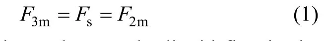
whereF3m,FsandF2mdenotes the liquid flux in the three-phase mixer, the three-phase settler and the two-phase mixer, respectively.
Therefore, it is reasonable, in this circumstance,to ignore the influences from three liquid flows on the partition of the two phenols in the three phases, and to use a separate beaker to simulate the three-phase mixer, three-phase settler and two-phase mixer, respectively. Therefore, we can obtain the effect of the operation parameters of each independent chamber on separation efficiency of two phenols.
3.2 Three-liquid-phase mixer
Agitation intensity and agitation time (i.e. retention time) in mixer are key operation parameters to affect the liquid-liquid mass transfer efficiency [25, 26].Fig. 2 depicts the partition of two phenols in three different liquid phases when agitating at 300 r·min-1for 15 min. As shown in Fig. 2, when three-phase extraction reaches final equilibrium,o-NP distributes mainly in the organic top phase with a mass percentage of about 80%, while most ofp-NP is enriched into the polymer middle phase with a mass percentage of above 90%. Both two compounds remain low mass percentages of below 10% in the bottom salt aqueous phase after the TLPE processes. Therefore, two compounds could be separated well by the proposed TLPS.
It is found that two phenols have different distributing behaviors in TLPE with the variation of agitating speed and agitating time. The relationship is expressed as follows:

Hereirepresentso-NP orp-NP,jrepresents one of the three phases,wi,jdenotes the mass percentage ofo-NP orp-NP in the three phases.t3m(i) andr3m(i) describe the agitating time and agitating speed in the three-phase mixer respectively.S3mis a structural factor related to the corresponding structure of three-phase mixer. And it is a constant in experiments.
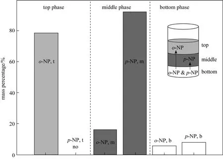
Figure 2 The partition of two phenols in the three-layered liquid phases (Agitating at 300 r·min-1 for 15 min for the extraction reaches final equilibrium. o-NP: o-nitrophenol, p-NP: p-nitrophenol, t: top phase, m: middle phase, b: bottom phase, Vt∶Vm∶Vb=1∶2.1∶1.7)
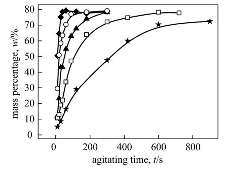
Figure 3 Mass percentages of o-NP in the top phase with agitating time at different agitating speedsagitating speed/r·min-1: ◆ 500; ○ 400; ▲ 300; □ 250; ★ 200
Figures 3 and 4 show the variation of the mass percentage ofo-NP in the top and middle phase, respectively, with agitating time at different agitating speeds. Obviously, there is certain connection between the increasing ofo-NP in organic top phase and the decreasing ofo-NP in PEG-rich middle phase. We suppose thato-NP is extracted gradually from the PEG-rich middle phase into the top organic phase with the increasing of agitating time. In fact, the increase of agitating speeds result in an obvious increase in three-liquid-phase mass transfer rate. Experimental observation manifested that the mass transfer of two phenols between polymer aqueous two phases were quick enough (see Figs. A1-A5). Therefore, the transfer ofo-NP from the PEG-rich phase into the organic phase depends on the degree of dispersion of organic phase into the polymer aqueous biphasic medium. It was observed that agitating at above 200 r·min-1was enough to ensure the satisfied mixing of three liquid phases. The increase in agitating speed creates more intensive dispersion and the decrease in size of dispersed organic liquid particles promotes the interphase mass transfer. Mass percentage ofo-NP in top organic phase increases and reaches an equilibrium state finally at all agitation speeds.
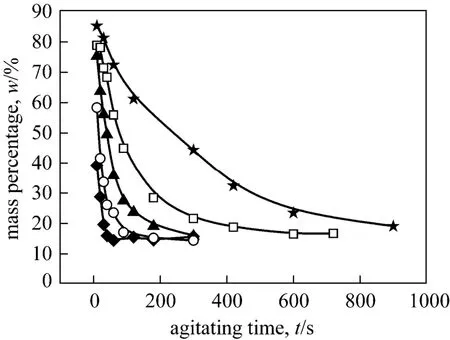
Figure 4 Mass percentages of o-NP in the middle phase with agitating time at different agitating speedsagitating speed/r·min-1: ★ 200; □ 250; ▲ 300; ○ 400; ◆ 500
Figure 5 depicts the partition behavior ofp-NP in PEG-rich middle-phase at different agitating speeds.The mass percentages ofp-NP remain unchangeable around 90%. It was manifested that the mass transfer ofp-NP between the two aqueous phases reaches the equilibrium within several seconds, even at low agitation of 200 r·min-1. Therefore, the mass fractions ofp-NP in the middle phase are hardly affected by the agitation intensity and retention time.

Figure 5 Mass percentages of p-NP in the middle phase with agitating time at different agitating speed
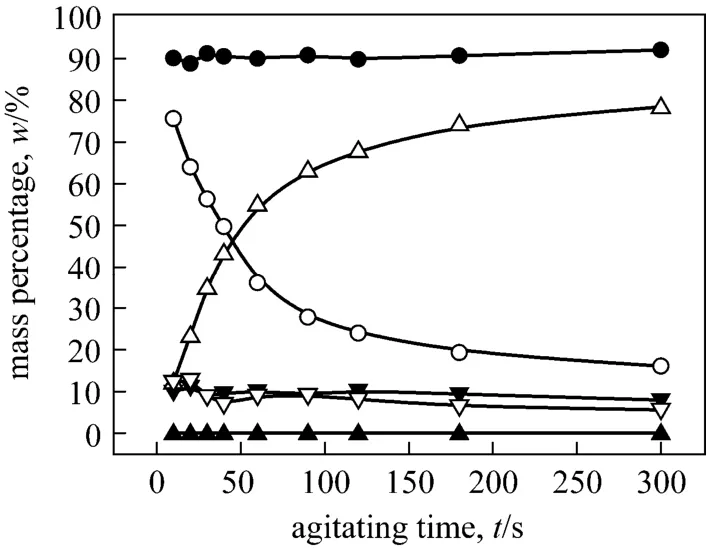
Figure 6 Mass percentages of o-NP and p-NP, respectively, in the three phases with the agitating time (Agitating at 300 r·min-1. o-NP: o-nitrophenol, p-NP: p-nitrophenol. t:top phase, m: middle phase, b: bottom phase)▲ p-NP, t; ● p-NP, m; ▼ p-NP, b; △ o-NP, t; ○ o-NP, m;▽ o-NP, b
The retention time in the three-phase mixer is a key factor to affect the interphase mass transferring ofo-NP. In fact, the retention time of three mixed liquid phases in the three-phase mixer is dependent upon the liquid fluxes during the TLPE process. The larger liquid flux is, the shorter retention time of the mixture is. Fig. 6 shows the variation of the mass percentages of two phenols in three phases with the increase of agitating time. Obviously, the increase of retention time favors the interphase mass transferring ofo-NP from the PEG-rich middle phase into the top organic phase.Experiments were also performed at different agitating speeds (200 r·min-1, 250 r·min-1, 400 r·min-1, 500 r·min-1), and same conclusions can be drawn (see Figs.A1-A5).
3.3 Three-liquid-phase settler
The emulsified dispersion band occurs after agitating between two clarified liquid phases in the process of liquid-liquid extraction. It is an important characteristic related to the interphase mass transfer [25].Some studies were reported on the behavior of dispersion band in traditional mixer-settler, and the steady state dispersion band height in a continuous industrial settler was predictable [27, 28]. In TLPE, the mixture flows into the three-phase settler, and begins to clarify and separate into three immiscible liquid phases. Two dispersion bands occur among three liquid layers in Fig. 7: one between the top and middle phases, and the other between the middle and bottom phases.
We defineH1andH2as the thickness of two dispersion bands, respectively, as depicted in Fig. 7. The two dispersion bands diminish gradually with the settling time, and two clear interfaces appear to divide the system into three clear liquid phases.
As shown in Figs. 8 and 9, the decaying of the two dispersion bands with the settling time display different behaviors. The agitating speed in three-phase mixer exerts an intense impact on the decay of dispersion band 1. The thickness of dispersion band 1 decreases rapidly during the initial settling process.However, the larger the agitating speed, the higher the dispersion thickness and slower the settling process. It is indicated that dispersion band 1 reduces to zero after settling for 120 s, at agitating speed of 250 r·min-1.By contrast, the dispersion band 1 of 400 r·min-1and 500 r·min-1were still 2.5 mm and 6 mm thick, respectively, after settling for 960 s. This result demonstrates that a larger agitating speed results in more intensive emulsification and slower clarification between the top and middle two phases in TLPS.

Figure 7 Two supposed dispersion bands and the supposed sampling sites in the settler (H1 and H2: thickness of dispersion band 1 and dispersion band 2. Letters a-j: supposed sampling sites. The extraction percent of p-NP and o-NP at each sampling site are described in Fig. 10)
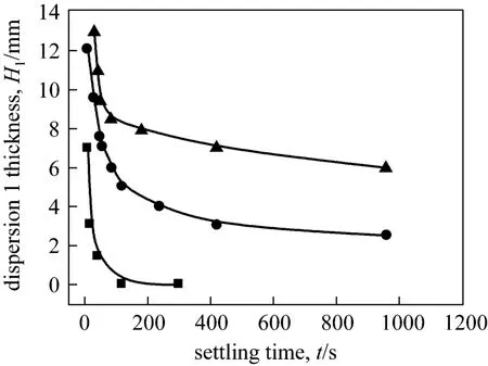
Figure 8 The thickness of dispersion band 1 with settling time at different agitating speeds
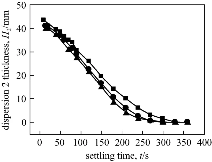
Figure 9 The thickness of dispersion band 2 with settling time at different agitating speeds
On the other hand, the agitating speed has little effect on the decay of dispersion band 2. The decrease of dispersion band 2 is almost linear with the settling time. After about 300 to 350 s of settling, the dispersion band 2 at different agitating speeds all decrease to zero. The behavior of dispersion band 2 may attribute to the nature of aqueous biphasic systems. It is a rapid process for phase separation between the polymerbased aqueous two phases [29].
The decay of a dispersion band is related to two main factors, agitating intensity and liquid flux (inversely the settling time), which is expressed as

whereFsis the total liquid flux through the three-phase settler,r3mis the agitating speed in the three-phase mixer.
The total liquid flux of the three-phase mixture is defined as
whereVsis the volume of the three-phase mixture through the three-phase settler, andtsis the settling time of the three-phase system in the settler.
Therefore, we have
In the experiments, the influences from the three-phase liquid flux on the thickness of dispersion band were ignored. Therefore,Vsis in fact the volume of the three-phase settler, and it is a constant.
From Eqs. (3) and (5), we have
Therefore, the behavior of the dispersion band is related to the agitating speed in the three-phase mixer.The increase of agitating speed in three-phase mixer results in the increase of the emulsion intension of dispersion band in three-phase settler.
Samples were taken from the clarified liquid phases in the process of three-phase settling to investigate whether the appearance of dispersion bands affects the extraction result of the two phenols. Fig. 10 shows that the mass percentages of two phenols don’t change along with the settling time even with the existence of two dispersion bands.

Figure 10 Mass percentages of two phenols versus settling time (Letter a-j: mass percentage of p-NP or o-NP at supposed sampling sites in the three-phase settler, and the sites are described in Fig. 7 with corresponding letters)● p-NP, middle; ■ o-NP, top
3.4 Two-liquid-phase mixer
There are two main purposes for the designing of the two-phase mixer. One is to promote the further mass transferring of the components in the separated two-phase mixtures separated by the liquid-flow controller set behind the three-phase settler. Another is to control the phase-forming behavior of the two-phase mixture to obtain a stable three-liquid-phase system in the three-phase settler in the next stage. The middle and bottom phase of TLPS usually constitute an aqueous two-phase system, and the phase ratio of the aqueous biphasic system results from the relative flux of the two liquid flows. The variation of liquid flux results in an obvious change in phase-forming behavior of the two-phase mixture. Table 1 shows the phase-forming behavior of PEG-(NH4)2SO4aqueoussolution changes with the (NH4)2SO4mass percent in the biphasic system.
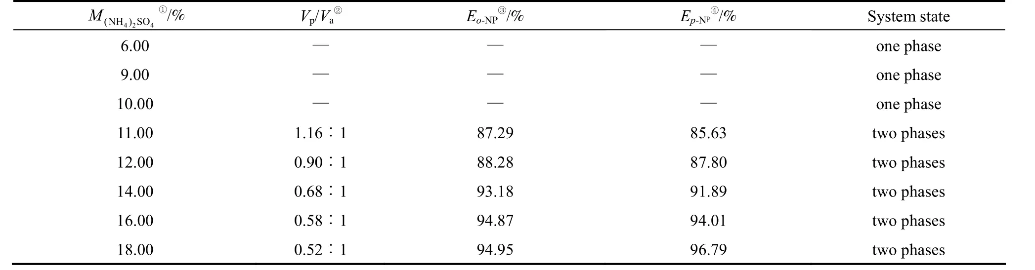
Table1 The phase-forming behavior of PEG-(NH4)2SO4 aqueous solution changes with increasing (NH4)2SO4 amount
As shown in Table 1, aqueous PEG-(NH4)2SO4solutions separate into two immiscible liquid phases when the mass percent of (NH4)2SO4is above 11%. In this case, a stable three-liquid-phase system is available when an organic extractant is added into the current two-phase mixtures.
Figure 11 shows the experimental result thato-NP andp-NP are both extracted into the PEG-rich phase in the aqueous PEG-(NH4)2SO4biphasic extraction, and their mass percentages reach both around 90% without changing with the agitating time.
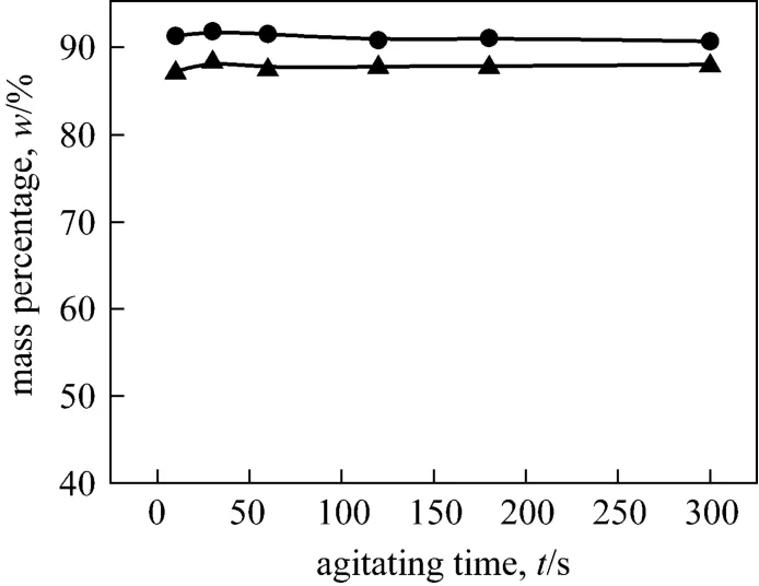
Figure 11 Mass percentage of o-NP and p-NP in PEG2000 phase (Agitating at 400 r·min-1)
After aqueous two-phase mass transfer, the two-phase mixture is delivered into the next stage to contact with the organic top phase from the three-phase settler.o-NP will be extracted from PEG-rich phase into nonane phase and separated withp-NP, whilep-NP remains in the PEG-rich phase. If the three-phase mixing doesn’t achieve an equilibrium state and flows into the settler for clarification, the top and middle phases or middle and bottom phases can be inducted into the two-phase mixer by the liquid-flow controller for further mixing and mass transfer.
4 CONCLUSIONS
A new mixer-settler-mixer three chamber integrated extractor was proposed for three-liquid-phase separation of two phenols,o-nitrophenol (o-NP) andp-nitrophenol (p-NP). The two phenols were respectively enriched into the top nonane phase and middle PEG-rich phase. Experimental results demonstrated that the agitating speed and retention time in three-phase mixer affect the mass transfer of the two nitrophenols.Different agitating speeds result in variation of thickness of two dispersion bands. However, the mass percentages of two phenols don’t change along with settling time with the appearance of two dispersion bands.The increase of salt concentration in bottom aqueous phase results in an obvious variation of phase-forming behavior of the resultant aqueous biphasic system and that of the corresponding phase volumes. The function of the two-phase mixer followed the three-phase settler is to enhance further mass transfer between the separated two phase mixtures and create a stable two-phase system before contacting with the third phase. The present works provide an approximate analysis on the behaviors of each chamber in TLPE extractor operating in batch mode. However, the results will benefit a feasible structural design of continuous and countercurrent TLPE process.
NOMENCLATURE
Cbconcentration ofo-NP orp-NP in the bottom phase
Ciconcentration ofiin the objective phase
Cmconcentration ofo-NP orp-NP in the middle phase
Ctconcentration ofo-NP orp-NP in the top phase
Fsflow quantity of mixture in the three-phase settler
F2mflow quantity of mixture in the two-phase mixer
F3mflow quantity of mixture in the three-phase mixer
Hthickness of the dispersion band
H1,H2thickness of the dispersion bands 1 and 2
r3magitating speed in three-phase mixer
tssettling time in three-phase settler
t3mretention time of mixture in three-phase mixer
Vbvolume of bottom phase
Vivolume of objective phase
Vmvolume of middle phase
Vsvolume of mixture in three-phase settler
Vtvolume of top phase
wi,jmass percentage ofiin phasej
Subscripts
b bottom phase
io-nitrophenol orp-nitrophenol
jphase
m middle phase
s settling
t top phase
2m mixing in two-phase mixer
3m mixing in three-phase mixer
1 Mojski, M., Gluch, I., “Characteristics and applications of three-phase extraction systems”,J.AnalChem., 51, 329-342 (1996).
2 Chen, J., Liu, H.Z., Wang, B., “Study on the three-phase extraction of penicillin G with a single step method”, In: Proceedings of the Conference on Solvent Extraction (ISEC2002), Cape Town,602-606 (2002).
3 Da Silva, L.H.M., Loh, W., “Polymer induced multiphase generation in water/organic solvent mixtures. Strategies towards the design of triphasic and tetraphasic liquid systems”,Chem.Commun., 7,787-788 (1998).
4 Palma, M.S.A., Shibata, C., Paiva, J.L., Zilli, M., Converti, A.,“Batch liquid-liquid extraction of phenol from aqueous solutions”,Chem.Eng.Technol., 33 (1), 39-43 (2010).
5 Palma, M.S.A., Paiva, J.L., Zilli, M., Converti, A., “Batch phenol removal from methyl isobutyl ketone by liquid-liquid extraction with chemical reaction”,Chem.Eng.Process., 46, 764-768 (2007).
6 Jiang, H., Fang, Y., Fu, Y., Guo, Q.X., “Studies on the extraction of phenol in wastewater”,J.Hazard.Mater., B101, 179-190 (2003).
7 Deng, T., Huang, L.J., Fu, L., “Synergistic extraction of gallium from sulfate solution”,Chin.J.Chem.Eng., 10 (1), 112-115 (2002).
8 Xie, K., Zhao, J.M., Yang, L.R., Yu, P.H., Liu, H.Z., “Investigation of three-liquid-phase extraction systems for the separation of Ti(IV),Fe(III) and Mg(II)”,Sep.Purif.Technol., 76, 191-197 (2010).
9 Xie, K., Huang, K., Xu, L., Yu, P.H., Yang, L.R., Liu, H.Z.,“Three-liquid-phase extraction and separation of Ti(IV), Fe(III), and Mg(II)”,Ind.Eng.Chem.Res., 50, 6362-6368 (2011).
10 Merchuk, J.C., Andrews, B.A., Asenjo, J.A., “Aqueous two-phase systems for protein separation Studies on phase inversion”,J.Phys.Chem.B, 711, 285-293 (1998).
11 Huddleston, J.G., Willauer, H.D., Griffin, S.T., Rogers, R.D.,“Aqueous polymeric solutions as environmentally benign liquid/liquid extraction media”,Ind.Eng.Chem.Res., 38, 2523-2539(1999).
12 Nandini, K.E., Rastogi, N.K., “Liquid-liquid extraction of lipase using aqueous two-phase system”,Food BioprocessTechnol., 4,295-303 (2011).
13 Hu, Z., Hu, X., Cui, W., Wang, D., Fu, X., “Three phase extraction study. II. TBP-kerosene/H2SO4-TiOSO4system and the preparation of ultrafine powder of TiO2”,Colloids Surf.A, 155, 383-393 (1999).
14 Shen, S.F., Chang, Z.D., Sun, X.H., Liu, H.Z., “Process integration for production of 6-aminnopenicillanic acid from penicillin G fermentation broth”,Process Biochem., 41, 571-574 (2006).
15 Jiang, Y.Y., Xia, H.S., Guo, C., Mahmood, I., Liu, H.Z., “Enzymatic hydrolysis of penicillin for 6-APA production in three-liquid-phase system”,Appl.Biochem.Biotechnol., 144, 145-159 (2008).
16 Shen, S.F., Chang, Z.D., Liu, H.Z., “Three-liquid-phase extraction systems for separation of phenol andp-nitrophenol from wastewater”,Sep.Purif.Technol., 49, 217-222 (2006).
17 Shen, S.F., Chang, Z.D., Liu, J., Sun, X.H., Hu, X., Liu, H.Z.,“Separation of glycyrrhizic acid and liquiritin from glycyrrhiza uralensis fisch extract by three-liquid-phase extraction systems”,Sep.Purif.Technol., 53, 216-223 (2007).
18 Gaur, R., Sharma, A., Khare, S.K., Gupta, N.M., “A novel process for extraction of edible oils enzyme assisted three phase partitioning(EATPP)”,Bioresour.Technol., 98, 696-699 (2007).
19 Liu, L., Dong, Y.S., Xiu, Z.L., “Three-liquid-phase extraction of diosgenin and steroidal saponins from fermentation of Dioscorea zingibernsis C.H. Wright”,Process Biochem., 45, 752-756 (2010).
20 Yu, P.H., Chang, Z.D., Ma, Y.C., Wang, S.J., Cao, H.B., Hua, C.,Liu, H.Z., “Separation ofp-nitrophenol ando-nitrophenol with three-liquid-phase extraction system”,Sep.Purif.Technol., 70,199-206 ( 2009).
21 Wang, J.D., Chen, J.Y., Solvent Extraction Manual, Chemical Industry Press, Beijing, 180-395 (2001). (in Chinese)
22 Zhou, J.Z., Duan, W.H., Xu, J.Q., Yang, Y.Y., “Experimental and simulation study on the extraction ofp-cresol using centrifugal extractors”,Chin.J.Chem.Eng., 15 (2), 209-214 (2007).
23 Ren, X.G., Song, Y.J., “A study on a gas agitated extractor with static mixer”,Chin.J.Chem.Eng., 6 (4), 361-365 (1998).
24 Tang, X.J., Luo, G.S., Wang, J.D., “Mass transfer and axial mixing characteristic in a coalescence-dispersion pulsed-sieve-plate extraction column”,Chin.J.Chem.Eng., 12 (6), 857-861 (2004).
25 Khakpay, A., Abolghasemi, H., “The effects of impeller speed and holdup on mean drop size in a mixer settler with spiral-type impeller”,Can.J.Chem.Eng., 88, 329-334 (2010).
26 Chen, Z., Pruss, J., Warnecke, H.J., “A population balance model for disperse systems: Drop size distribution in emulsion”,Chem.Eng.Sci., 53, 1059-1066 (1998).
27 Jeelani, S.A.K., Hartland, S., “Prediction of steady state height from batch settling dispersion data”,AlChE J., 31 (5), 711-720 (1985).
28 Jeelani, S.A.K., Hartland, S., “Dynamic response of gravity settlers to changes in dispersion throughput”,AIChE J., 34 (2), 335-340(1988).
29 Rajni, H.K., “Aqueous two-phase systems”,Mol.Biotechnol., 19,269-277 (2001).
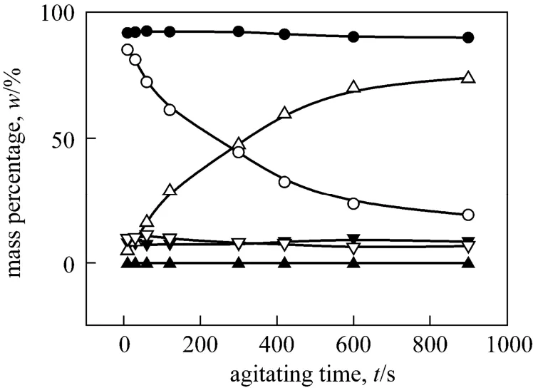
Figure A1 Mass percentages of o-NP and p-NP change with agitating time in the three phases respectively (Agitating at a constant speed of 200 r·min-1. o-NP: o-nitrophenol,p-NP: p-nitrophenol, t: top phase, m: middle phase, b: bottom phase)
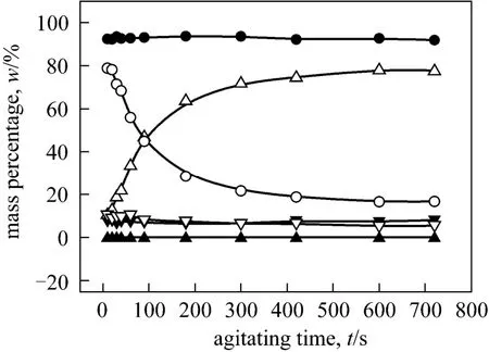
Figure A2 Mass percentages of o-NP and p-NP change with agitating time in the three phases respectively (Agitating at a constant speed of 250 r·min-1. o-NP: o-nitrophenol, p-NP:p-nitrophenol, t: top phase, m: middle phase, b: bottom phase)
APPENDIX▲p-NP, t; ●p-NP, m; ▼p-NP, b; △o-NP, t; ○o-NP, m;▽o-NP, b
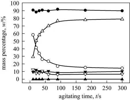
Figure A3 Mass percentages of o-NP and p-NP change with agitating time in the three phases respectively (Agitating at a constant speed of 400 r·min-1. o-NP: o-nitrophenol, p-NP:p-nitrophenol, t: top phase, m: middle phase, b: bottom phase)▲ p-NP, t; ● p-NP, m; ▼ p-NP, b; △ o-NP, t; ○ o-NP, m;▽ o-NP, b
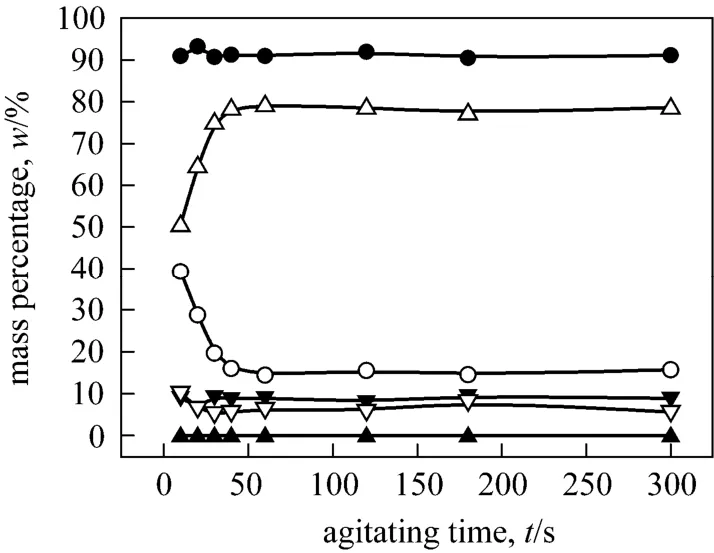
Figure A4 Mass percentages of o-NP and p-NP change with agitating time in the three phases respectively (Agitating at a constant speed of 500 r·min-1. o-NP: o-nitrophenol, p-NP:p-nitrophenol, t: top phase, m: middle phase, b: bottom phase)

Figure A5 Distribution of o-NP and p-NP in aqueous biphasic system when agitating at different speed [Agitating for 10 s at each agitating speed. o-NP: o-nitrophenol, p-NP:p-nitrophenol, t: top phase (PEG phase), b: bottom phase(aqueous phase)]▲ p-NP, t; ▼ p-NP, b; △ o-NP, t; ▽ o-NP, b
猜你喜欢
杂志排行

Chinese Journal of Chemical Engineering的其它文章
- Retrospect and Perspective of Micro-mixing Studies in Stirred Tanks*
- In-situ Synthesis and Catalytic Properties of ZSM-5/Rectorite Composites as Propylene Boosting Additive in FluidCatalytic Cracking Process*
- Low-temperature Electrodeposition of Aluminium from Lewis Acidic 1-Allyl-3-methylimidazolium Chloroaluminate Ionic Liquids*
- Solvent Extraction of Yttrium by Task-specific Ionic Liquids Bearing Carboxylic Group*
- Micron-sized Magnetic Polymer Microspheres for Adsorption and Separation of Cr(VI) from Aqueous Solution*
- Study on Kinetics of Iron Oxide Reduction by Hydrogen*