A New Single DIFAR Sonobuoy Target Location Algorithm
2011-07-25TAOLinwei陶林伟WANGYingmin王英民
TAO Lin-wei(陶林伟),WANG Ying-min(王英民)
(School of Marine Engineering,Northwestern Polytechnical University,Xi’an 710072,Shaanxi,China)
Introduction
Sonobuoy is an important anti-submarine detection equipment for the fixed-and rotary-wing anti-submarine aircrafts.In the battle,the anti-submarine aircrafts lay some certain arrays of sonobuoy along a searching route.When the sonobuoy arrives at the water surface,it automatically divides into two subsystems:underwater and water surface.Underwater sensor system automatically sinks to a predetermined depth,and detects the submarine targets;the water surface system communicates with the underwater system through the cables,and sends the detected information to the anti-submarine aircrafts patrolling over the sea area through the antenna of the water surface sonobuoy.The anti-submarine aircrafts(or notify other anti-submarine platforms)conduct an integrated processing of data to complete the target detection,location,tracking,and attacking[1-2].
According to different functions,the buoy system can be divided into five different categories:low-frequency acquisition and ranging(LOFAR),directionfinding and ranging(DIFAR),active omnidirectional,temperature depth,and ocean noise.DIFAR buoy is an important one among them.
DIFAR buoy has a receiving array with directivity,and can use single buoy to locate the targets.DIFAR buoy amplifies,filters,conditions and digitizes the analog signals from underwater sensor while it operates.And it sends VHF FM radio signals to the antisubmarine aircrafts.The buoy receivers on the aircraft receive and demodulate the signals,and detect,identify and locate the targets with the help of the on-board powerful signal processing system.
The anti-submarine aircraft usually needs 4-6 LOFAR sonobuoys to roughly identify the target positions.If four passive location(DIFAR)sonobuoys are added,the target can be precisely positioned.If one more active directional sonobuoy is used,the accurate target position can be gotten[3].Currently the DIFAR buoy location algorithm mainly uses DIFIX(DIFAR FIX,DIFAR buoy location)method.This algorithm requires at least two DIFAR buoys to locate a target,and uses the measured azimuth lines of two buoys and refers to their own positions to locate the target.
With the rapid development of microelectronics and integrated circuit technology,the processing speed of the microprocessor enhances dramatically.The cor-responding processing capacity of next generation buoy on-board signal processing center will be greatly improved.Spectrum analysis has become the basic function of processing center.The frequency analysis accuracy can be achieved to 0.1 Hz through the use of FFT,ZOOM-FFT and other algorithms.In such a situation,a new DIFAR buoy location algorithm is proposed for the next generation of buoy platform of highperformance signal processing center.In the calculation process of this method,the target Doppler information is added,and the calculation function of single sonobuoy for the target motion features is achieved,which greatly improves the operational flexibility and efficiency of buoy and has an important practical significance.
1 Classical DIFIX Location Method
DIFIX location method requires at least two buoys to locate a target.As shown in Fig.1,the coordinates of DIFAR buoysB1andB2are(x1,y1)and(x2,y2),and the coordinate of targetAis(x,y).The buoys measure the target positionsθ1andθ2respectively,and calculate the coordinate of targetAaccording to their own coordinates.
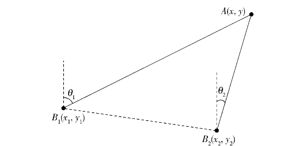
Fig.1 Classical DIFAR location model
According to the geometric principle,we can obtain
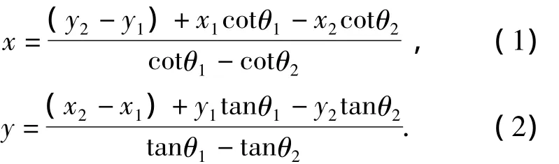
It can be seen that the classical DIFAR buoy location algorithm firstly measures the target position relative to the buoys,and then calculates the target position according to the coordinates of the buoys.The accuracy of this algorithm mainly depends on the direction finding error and the location error of the buoy itself.The advantage of DIFIX is that it could locate the uniform speed and non-uniform speed targets in realtime.
2 Single DIFAR Sonobuoy Location Algorithm
The new generation of buoy signal processing system can complete a line spectrum tracking,line spectrum power calculation,DIFAR analysis,relative azimuth calculation and other data processing of the DIFAR buoys.These processes can bring more information to make a single DIFAR buoy complete the target positioning.
A model is established as follows.A buoy is taken as a coordinate origin,north asyaxis,and east asxaxis,as shown in Fig.2.A target moves in uniform linearity at speedv.The angle between the target and the north direction isφT.The buoy relative orientation measured by the DIFAR buoy isφi(for all the included angles,the north direction is used as reference,the clockwise direction is positive).

Fig.2 New DIFAR location model
Through line spectrum tracking,DIFAR buoy can obtain the target Doppler frequency shift[4]:
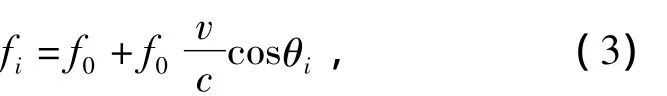
wherefiis the frequency of target for theith measurement,f0is the feature frequency of target,vis the target speed,cis the propagation velocity of sound in seawater,θiis the bearing angle between the target moving direction and the connecting line of target and DIFAR buoy.
When the target approaches the buoys from a dis-tance,passes through the CPA point(closest point of approach)and eventually departs from the buoys,it can be known from Eq.(3)that the line spectrum detected by the DIFAR buoys changes from big to small.When the target passes through the CPA point,the change of line spectrum is the biggest,viz,the CPA point is the inflection point of the line spectrum curve[5-6].
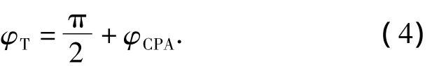
The DIFAR buoy can determine the timetCPAby use of the detected target line spectrum when the target passes through the CPA point,and the position of this time is denoted asφCPA.
According toφCPA,the course of the target can be easily obtained:
After gettingφT,we could obtainθi,

Through any two measurements of the frequencyfm,fn,
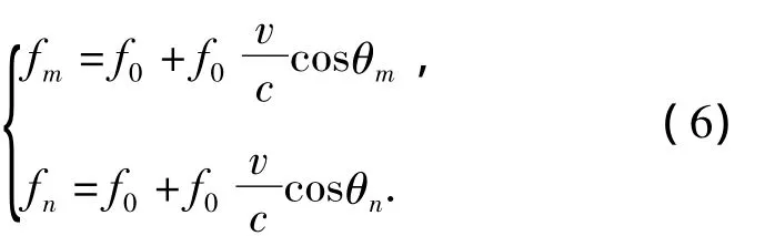
The feature frequencyf0and actual speedvof target can be gained from Eq.(6).
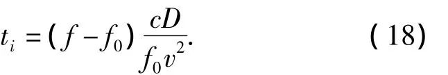
If theith measurement time isti,we have

On the basis of Sine theorem,

whereDis the distance between the buoy and the nearest point of the target.From Eq.(8)Dcan be calculated

After the three motion factors are obtained,the positions of the target at any time can be gotten.
3 Algorithm Improvement
3.1 Calculation Improvement for Velocity v and Feature Frequency f0
Eq.(6)only uses two measured frequency values to calculate the target velocityvand feature frequencyf0,but in practice a number of frequency measurements may be made.In order to effectively use the frequency data and improve the calculation accuracy,we could calculate the optimal solution in the Least Square sense.
According to Eq.(6),we construct the following equation:

Eq.(10)is written as

where
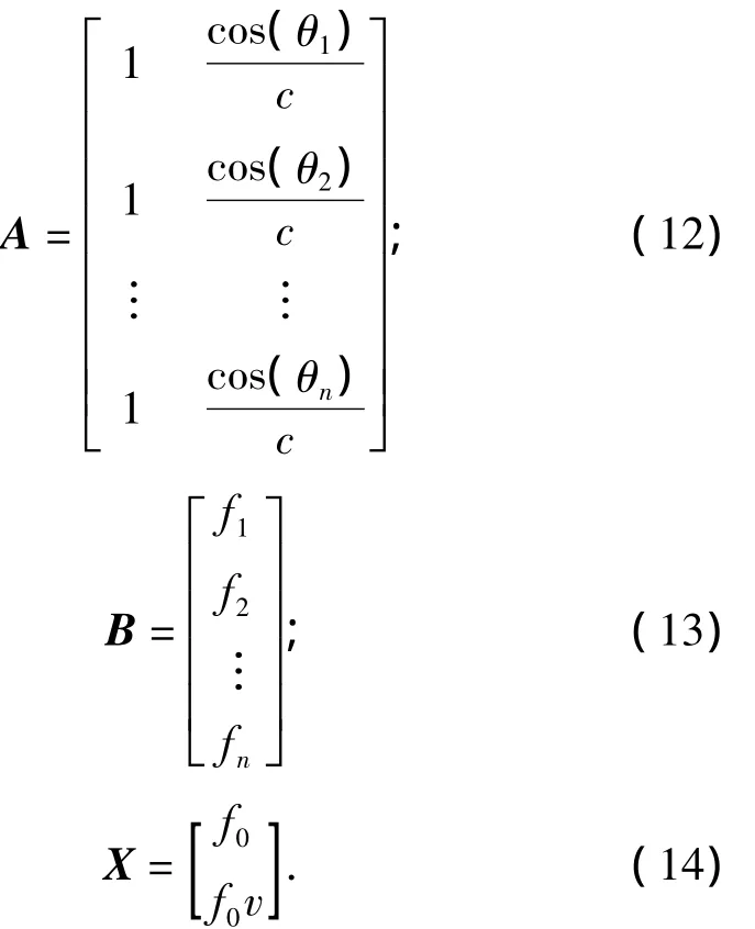
The Least Square solution is

3.2 Calculation Improvement for the Distance D
When the distance is calculated,multipleDs can be calculated according to multiple measurement anglesφi,θiand timeΔTi,and then they are averaged,which can reduce the impact due to the angle measurement errors to some extent.
4 Error Analysis and Simulation
The two parameters,the time when the target passes through the CPA point and the target position of this time,are the first step of the whole algorithm and are also the basis of subsequent calculations.Therefore,the estimated accuracy of the two parameters directly affects the accuracy of the follow-up results.
The error at the time of CPA point is shown in Fig.3.For the calculation simplicity,the time when the target passes through the CPA point is assumed to be time 0.

Fig.3 Target passing through CPA point


A Taylor expansion of Eq.(16)at thetCPApoint(i.e.time 0)is made,and the first order term is reserved,we have
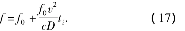
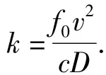
Time can be expressed as:
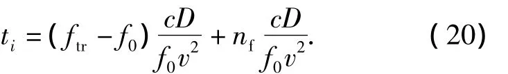
Let the error of measurement frequency be Gaussian white noisenf,then the measured frequency can be expressed as:

whereftrdenotes the true value of the frequency.Eq.(19)is substituted into Eq.(18),we have
In order to validate and analyze the algorithm,two groups of computer simulation are carried out.Owing to the limited size of underwater array of DIFAR buoy,the direction finding accuracy is poor.The direction finding mean square error is set to be 5°.
However,the frequency measurement is completed by the integrated signal processing system of buoy.The maximum error is set to be 0.1 Hz.

After simulation,four parameters of target reliably converge.
The relative errors of the four parameters are shown in Fig.4.
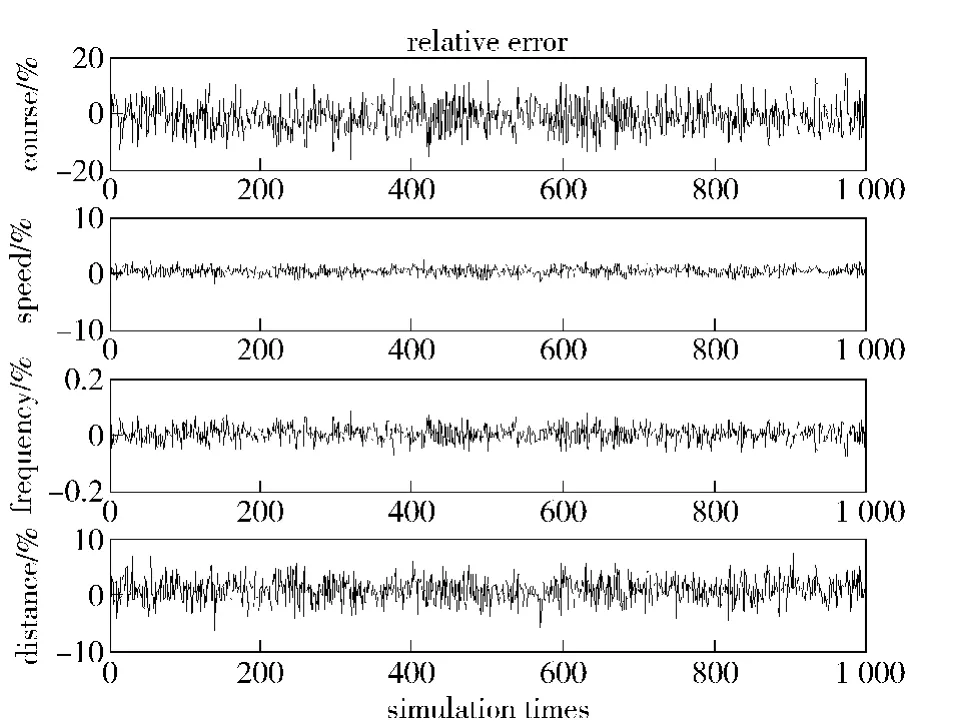
Fig.4 The first set of simulated results
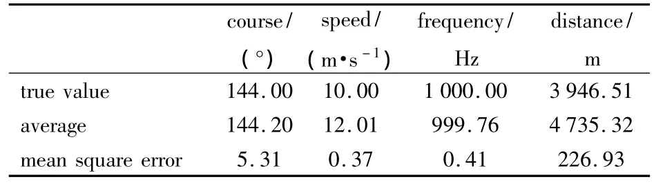
The statistical simulated results are listed in Tab.1.

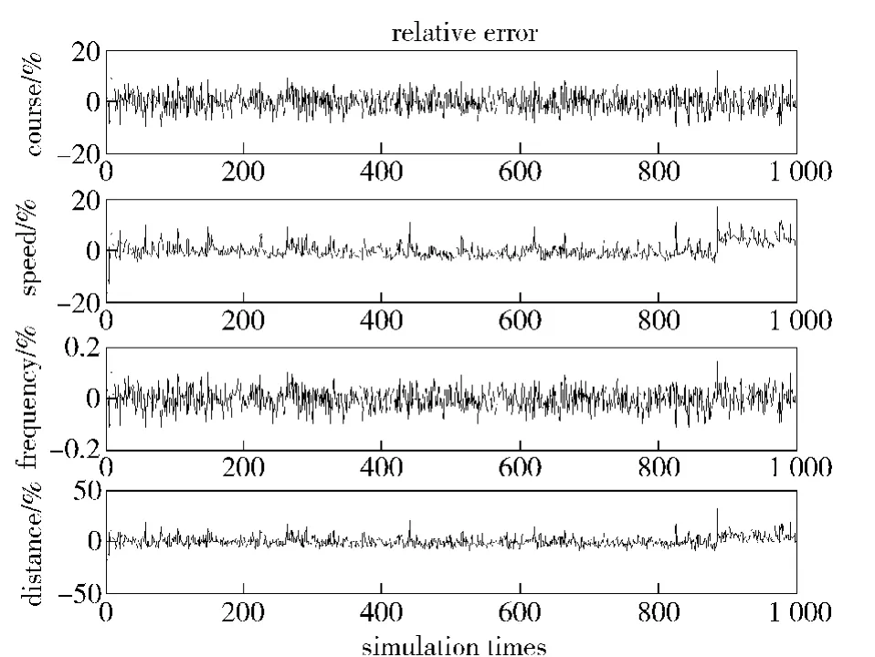
Fig.5 The second group of simulation results
The statistical simulated results are listed in Tab.2.
Tab.2 Statistic results of 1 000 simulations
The simulated results are consistent with the error analysis. When the target distance increases, the speed decreases and the feature frequency becomes lower,the time estimation error increases.
It can be seen from the results that the simulation achieves very good results,and the four parameters of the target stably converge.A large number of the measurements of Doppler information participating in the calculations,the calculation of target feature frequency is the most accurate.Whereas the target position is the single measurement result of the measuring orientation after smooth filtering,so the simulated results undulate greatly,the mean square errors are up to 2.37°and 5.31°.The optimal solutions of the target speed and the closest distance can be derived through multiple measurements.The result is better compared to the orientation.Considering that the consequence of this algorithm is the location result of a single DIFAR buoy,and the direction finding error is more than 5°,this result is also satisfactory.
5 Conclusions
A new buoy signal processing system is discussed through the research on the single DIFAR buoy location algorithm and on the basis of former DIFIX location algorithm,and a new single DIFAR buoy location algorithm is proposed.The calculation process of this method is easy and reliable,and it’s easily implemented in engineering.The simulated results show the effectiveness and convergence of this method.This method has more military significance,it enhances the operational function of DIFAR buoy,improves the usage rate and operational efficiency of DIFAR buoy,and provides more buoy combat tactics.
[1]RONG Zhu.Airplane carry sonobuoy and dipping sonar[J].Modern Military,2006,(1):62-63.(in Chinese)
[2]ZHANG Xiao-li,CHEN Jian-yong.Joint application of dipping sonar and sonobuoy in answering the call to antisubmarine[J].Journal of Naval Aeronautical Engineering Institute,2006,21(6):669-671.(in Chinese)
[3]PAN Qin-sheng.Active omni-directional sonobuoy system[J].Acoustics and Electronics Engineering,1994,(1):39-41.(in Chinese)
[4]TIAN Tan,LIU Guo-zhi,SUN Da-jun.Sonar technology[M].Harbin:Harbin Engineering University Press,1999:21-24.(in Chinese)
[5]TAO Lin-wei,WANG Ying-min,WANG Cheng,et al.New algorithm for sonobuoy Doppler-CPA[J].Journal of System Simulation,2008,20(23):6353 -6355.(in Chinese)
[6]GONG Xu,CAI Yun-xiang.Passive directional sonobuoy’s Doppler effect location eechnique[J].Ship Electronic Engineering,2008,(10):174 -176.(in Chinese)
猜你喜欢
杂志排行

Defence Technology的其它文章
- Study on Effects of Diesel Engine Cooling System Parameters on Water Temperature
- A New Fusion Method for Conflicting Evidence
- Numerical Simulation and Performance Analysis on Windmill Starting Process of Small Turbojet Engine
- New Wideband Beam-forming Method Used in Underwater Communication System
- Research on Estimation of Time Delay Difference in Passive Locating for Impulse Signal
- Reliability Sensitivity Analysis for Location Scale Family