Experimental Investigation on Combustion Performance of Solid Propellant Subjected to Erosion of Particles with Different Concentrations
2011-03-09LUMingzhang卢明章ZHAOZhibo赵志博HEGuoqiang何国强LIUPeijin刘佩进
LU Ming-zhang(卢明章),ZHAO Zhi-bo(赵志博),HE Guo-qiang(何国强),LIU Pei-jin(刘佩进)
(Science and Technology on Combustion,Internal Flow and Thermal-Structure Laboratory,Northwestern Polytechnical University,Xi’an 710072,Shaanxi,China)
Introduction
In order to improve the specific impulse and avoid the high frequency chugging combustion,the propellant with aluminum is widely used in the modern SRM.Aluminum powder turns into condensed phase Al2O3particles after burning,which results in a typical two phase flow in SRM.The results of the numerical simulation for three-dimensional two phase flow show that,in overloading condition,especially horizontal overloading,the particles tends to deflect critically,and particle flow is easy to erode the surface of propellant[1].The high-temperature particle flow may gather on the propellant surface,change the propellant combustion performance and eventually influence the propellant’s combustion mechanism.Therefore,it is important to understand and master comprehensively the propellant combustion mechanism under particle erosion.Presently,only some fundamental studies in this subject have been conducted[2-4],and few of them involves the complexity of propellant combustion performance and the limitations of test devices.
In this paper,a test device to produce a rectangular particle erosion flow is developed to simulate the environment in SRM,in which the propellant combustion performance or the specific quality of the insulator can be studied under overloading conditions.Besides,contrast tests are carried out in the new device and the axially symmetric test device with circular channel,the results provide a reference for experiment research on the propellant combustion performance under different particle erosion.
1 Design of Test Device with Rectangular Channel
1.1 Design Requirements
While SRM maneuvers,the deflection and the erosion mode of the particle are complex and changeable due to the influence of horizontal and axial overloads.It is necessary to use the factor separation method in the study of the solid propellant combustion to ascertain the dominant factor.Therefore,the design of the developed test device focuses on the control of some important parameters,such as combustion chamber pressure,particle concentration,flow velocity and angle,granularity distribution,and so on.To simulate the erosion environment in the SRM combustion chamber,the structural design of the test device to produce the high concentration particle flow must be completely based on the simulation of the high-temperature particle erosion condition and lay stress on following factors:
1)The particle flow produced by the test device must guarantee a certain accumulation concentration;
2)It must facilitate the diagnosis of the combustion surface change under particle erosion;
3)It must satisfy the adjustment requirements of some important factors,such as the angle and velocity of the particle flow,and so on.
1.2 Structural Design and Functional Realization of Test Device
The structure of the developed test device with a rectangular channel is shown in Fig.1.Its internal flow channel is designed to be a rectangle to produce beltlike rectangular erosion flow.To inspect the solid propellant combustion performance,mainly burning rate change,under high-temperature particle erosion,it is necessary to obtain a relatively clear changing combustion diagnosis image of the eroded propellant.To regularize and clarify the eroded combustion surface,the particle flow should be belt-like and its cross section should be rectangular.Thus,the particle flow can produce a“knife cut”effect on the test sample surface.Observed from side direction,the eroded surface is obviously two-dimensional and its clarity is greatly enhanced.
Fig.1 Section of test device
Pressure,particle concentration,particle diameter and flow velocity and angle are important factors in the study.Therefore,these major parameters should be adjustable and controllable.The ways to realize these functions for the test device are as follows:
1)The combustion chamber pressure can be measured by pressure sensors and adjusted by changing the proportion of the burning surface to the nozzle throat area.
2)The particle concentration can be regulated within a certain range by changing the alumina powder content in propellant and modifying the configuration of the contraction section.The concentration of the accumulated particles can be obtained by using two phase flow simulation.
3)Flow velocity can be controlled by designing the adjustment section of the test device.Theoretically,the flow velocity can be changed by altering the two-phase flow outlet area.In practice,the adjustment section should cooperate with the contraction section,i.e.,the contraction section focuses on controlling the accumulation and figuration of the particle flow,while the adjustment section is used to adjust the particle velocity and its influence on the accumulation concentration should be reduced as little as possible.In the adjustment section design,splitting a convergent angle is preferable,instead of simple enlargement or reduction of the outlet.The appearance of adjusters 1,2 and 3 are split along the solid line,the dot dash line and the dotted line respectively,as shown in Fig.2.Thus,the adjustment section becomes an extension to the contraction section and its convergent angle can be deter-mined according to the burning surface size of the sample propellant and to the particle accumulation position.In fact,the convergent angle of the adjuster makes a secondary adjustment for the accumulation position.Only the slightest nuance is taken place in the cross section,the particle concentration will change a little,while its velocity quite sensitive to the outlet cross section changes greatly,and the velocity regulation is achieved in this way.
Fig.2 Section of adjuster
As the adjustment section is located in the region eroded critically,it should be made of heat-insulating material to prevent the velocity adjustment accuracy from the influence of the erosion.
4)The erosion angle can be changed by adjusting the slope of the test sample.
Moreover,as a significant input parameter in numerical simulation calculation,the particle diameter influences the erosion effect greatly.In this paper,it is not taken as an adjustment item and its numerical value can be obtained experimentally and statistically.
Replaced the propellant test sample by heat-insulating layer test sample,the test device developed in this paper can also be used to study the performance of insulator of SRM under similar particle erosion.
2 Configuration of Test Device with Axis-symmetric Circular Channel
To study the combustion performance of solid propellant under particle erosion,in our laboratory,an axis-symmetric test device with circular flow channel[5]is developed.Its structure is shown in Fig.3.In this paper,the device is used in contrast experiments with the rectangular test device.
Fig.3 Test device with circular channel
3 Numerical Simulations
3.1 Boundary Conditions and Grid Partition
Boundary conditions:When the tested propellant burns under the particle erosion,the burning surface produces the rising gas flow that makes an impact on the coming particle flow.Therefore,this burning surface can not be treated simply as a wall surface in boundary condition setting.Giving adequate consideration to the specific conditions,this paper takes the burning surface as a mass surface and the particle diameter can be determined according to the particle collection experiment results.
Grid partition:Three-dimensional grid geometry is shown in Fig.4.As the internal flow field of the test device is irregular,to obtain the most accurate numerical result,the grids should be regular and in order.The grids on experiment section and test sample are locally densified;the total number of the grids distributed in the whole calculation region is approximately 200 000.
Fig.4 Grid partition
3.2 Numerical Simulation Results
When some conditions,such as pressure,angle and particle granularity distribution are determined,the main factors to influence the combustion performance of solid propellant are flow velocity and particle concentration.
3.2.1 Flow Velocity
The velocity contours of gas phase in Fig.5 are obtained from two test devices,respectively,in the situations of 3.5 MPa in pressure and 45°in test section angle.According to the calculation results,the condensed phase particle velocity is close to the gas phase velocity.It can be seen that,jointly influenced by the scouring gas flow and the rising gas flow produced by propellant combustion,the gas phase velocity near the test sample burning surface changes drastically.The flow velocity mentioned in this paper is measured at the region of 2 mm above the burning surface center to obtain a consistent contrast standard for gas phase flow velocity in various conditions.
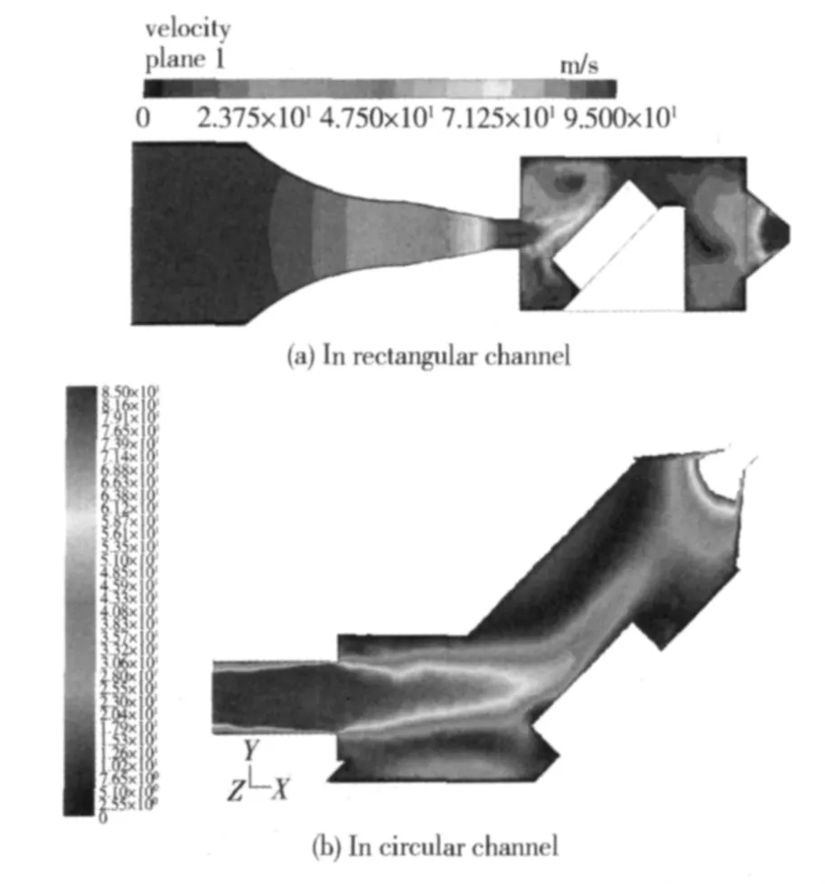
Fig.5 Gas velocity contours in different channels
3.2.2 Particle Concentration and Erosion Zone
Fig.6 shows the particle concentration distribution.It can be seen that the particle concentration reaches to maximum above the burning surface of the test sample and a certain particle scour is guaranteed.Moreover,the particle concentration on the test sample surface in the rectangular channel is comparatively lower than 6 kg/m3,but the rectangular outline of the particle flow is clear and it covers the burning surface of the test sample in Z direction,the horizontal direction of the test sample.It is helpful to obtain a comparatively clear two-dimensional image of the burning surface for combustion diagnosis.On the contrary,a huge accumulation of particles occurs in the circular channel and hence the particle concentration will be comparatively high and the highest value cab be up to 32.48 kg/m3,and it is helpful to study the influence of the high concentration particles on the propellant combustion performance.
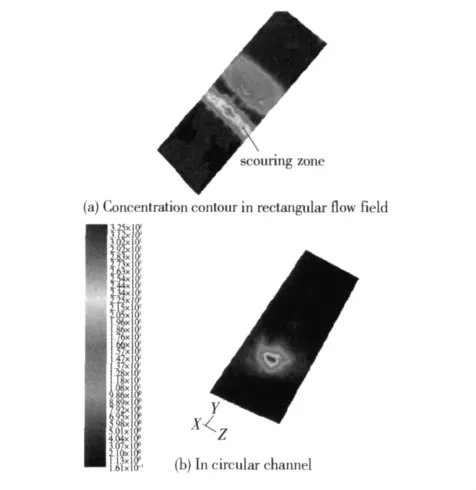
Fig.6 Particle concentration contour
4 Experiment Process and Results
4.1 Experiment Results in Rectangular Channel Test Device
Experiments 1,2,3 and 4,as shown in Tab.1,in the rectangular test device are conducted in 4 different conditions to study the combustion performance of solid prope-llant,and X-ray real-time radiography technique is used for the combustion diagnosis.For the experiment 3,X-ray images and the image after edge extraction and composition are shown in Fig.7.It can be seen that the relatively clear X-ray image of the regressing burning surface can be obtained experimentally.The burning surface generally regresses parallel in accordance with the parallel layer combustion mechanism,and no pits appear on the surface.
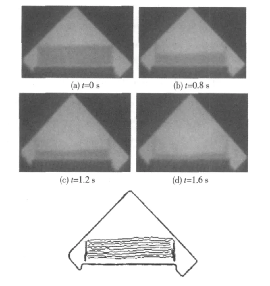
Fig.7 X-ray image and composition image of burning surfaces after edge extraction
As shown in Tab.1,the experiments 1,2 and 3 investigate the combustion properties of HTPB propellant with high static burning rate under different flow speeds,while experiment 4 tests HTPB propellant with low static burning rate.
It can be concluded from the experiments 1,2 and 3 that the particle velocity has little effect on the propellant combustion performance,and the maximum burning rate incremental ratio is less than 25%,if the particle concentration is lower than 6 kg/m3;while in the experiment 4 the propellant with low static burning rate is very sensitive to the particle erosion.
The test device with rectangular channel is effective to study the propellant combustion performance under particle erosion,and the experiment results show the combustion performance of propellant with different burning rates and different pressures.However,there is also an inadequacy in it.The particle concentration can not be high enough to study the propellant combustion under higher concentration particle erosion.It still has more improvement space.
4.2 Experiment Results in Circular Channel Test Device
The contrast experiments are conducted in the test device with a circular channel to study the propellant combustion performance under high concentration particle erosion.The experiments 5 and 6 investigate HTPB propellant with relatively low static burning rate.Fig.8 shows the X-ray image and composition image after edge extraction in experiment 6.With the lapse of time,some obvious pits appear on the burning surface,which means that the propellant combustion performance changes drastically in higher particle concentration.
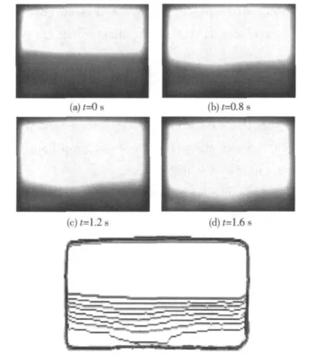
Fig.8 X-ray image and composition image of burning surfaces after edge extraction in experiment 6
In Tab.2,the maximum burning rate incremental ratio is up to 97%.Moreover,under high concentration particle erosion,the propellant combustion appears with certain regularity:the burning rate incremental ratio increases with the increase of the flow velocity.
Tab.2 High-concentration erosion test results
It can be seen from the experiments 1 to 8 that the particle concentration is also an important factor.If the particle concentration is higher than 20 kg/m3,the influence of the flow velocity on the propellant combustion can be reflected obviously.
The unclear RTR image and inaccurate data of the test device with circular channel makes an impact on the mechanism analysis of propellant combustion performance.
5 Conclusions
1)A test device with rectangular channel is developed to study the performances of propellant combustion and insulator in SRM.
2)CFD numerical simulation are conducted for the rectangular and circular flow fields in test devices,and contrast tests are carried out to study the solid propellant combustion performance under particle erosion.The results show:
(1)The rectangular channel can enhance the clarity and precision of combustion diagnosis image effectively,and it can be used to study the solid propellant combustion under low concentration particle erosion;
(2)The circular channel has good particle convergent effect and provides higher concentration particles.It can be used to study the solid propellant combustion performance under higher concentration particle erosion;
(3)The burning rate of propellant with low static burning rate increases drastically under particle erosion,while propellant with high static burning rate is not sensitive to the particle erosion;
(4)If the particle concentration is lower,the propellant burning rate changes only a little.
[1]HE Guo-qiang,WANG Guo-hui,CAI Ti-min,et al.Investigation on internal flow and insulalator erosion of SRM under high acceleration[J].Journal of Solid Rocket Technology,2001,24(4):4-8.(in Chinese)
[2]LIU Pei-jin,WANG Yong,LV Xiang,et al.Gas and particle velocity impact on the burning rate of HTPB solid propellant[J].Journal of Propulsion Technology,2008,29(3):278-281.(in Chinese)
[3]LI Jiang,LIU Yang,LOU Yong-chun,et al.Experimental investigation for the influence of particle on insulation erosion[J].Journal of Propulsion Technology,2006,27(1):71-73.(in Chinese)
[4]LIU Pei-jin,LV Xiang,HE Guo-qiang.Burning rate relativity investigation using artificial neural network[J].Journal of Propulsion Technology,2004,25(2):156-158.(in Chinese)
[5]LI Ying-chun,HE Guo-qiang,LIU Pei-jin,et al.Experimental study on effects of particle erosion on combustion property of HTPB propellant[J].Journal of Solid Rocket Technology,2008,31(1):551-555.(in Chinese)
杂志排行

Defence Technology的其它文章
- Study on CAD Data Interface to Geometry Description System
- Modeling and Simulation for Complex Repairable System with Built-in Test Equipment
- A New Synthesis Method for Sum and Difference Beam Pattern with Low Sidelobe
- An Evaluation Approach for Operational Effectiveness of Anti-radiation Weapon
- An Orthogonal Wavelet Transform Fractionally Spaced Blind Equalization Algorithm Based on the Optimization of Genetic Algorithm
- Prefix Subsection Matching Binary Algorithm in Passive RFID System