Study on CAD Data Interface to Geometry Description System
2011-03-09LIUXiangkai刘祥凯TANGYanfeng唐彦峰WANGJianing王佳宁LIHuimei李慧梅
LIU Xiang-kai(刘祥凯),TANG Yan-feng(唐彦峰),WANG Jia-ning(王佳宁),LI Hui-mei(李慧梅)
(Department of Automotive Engineering,Academy of Military Transportation,Tianjin 300161,China)
Introduction
The geometry description system(GDS)for target is a foundation for both vulnerability/lethally(V/L)assessment and battlefield damage simulation(BDS).Its basic function is to simplify and aid the target description,efficiently manage the name,geometric data,mechanical and physical parameters of each component of the target,calculate the vulnerable areas and estimate the shotline data of a target.
Usually,the construction and validation of a target's geometry description model is a very crucial and time-consuming task.The main problem is where and how the description data can be obtained.Currently,there are three data sources for modeling[1].
1)Blueprints,schematics,mechanical drawings or photographs.They can save time or resources and provide precise data with minimal data collection effort,and also suggest ways to structure the model,e.g.,by providing wiring diagrams,subsystem schematics,etc.But,sometimes,they may be difficult to read,and do not always show all needed measurement data or views.
2)Measurable object.It can arguably provide the best source of verifiable information byproviding hands-on access to the actual objects being modeled.But,it can be resource and labor intensive and limited by the objects'availability,accessibility and measurability.
3)Transformable geometric models.They can offer significant savings in data collection and/or measurement.But,they may have missing data,unfamiliar naming,and alternate or dissimilar geometry formats,e.g.,feature-based objects,spines,etc.,and can also be unsuitable for a given application because the original model is developed for different purposes.
With the development of CAD/CAM technology,more and more CAD models are used in design and production areas.To apply them in target description has become an important problem we face.Currently,there are two ways.
One of them is to convert and integrate the analysis program to a common CAD platform.Another is to bring and integrate the 3-dimension technique to V/L analysis program,such as BRL-CAD,directly.
In V/L field,each method is suitable,and can solve the modeling and analyzing works efficiently.But in battlefield damage assessment and repair(BDAR)field,some problems can not be solved.First,in a BDS system,there may exist hundreds of multi-kinds of equipment and threats,e.g.,tanks,vehicles,cannons,bombs,mines,etc.,under a complicated combat environment.And they need to be treated in a short time.The above methods are difficult to satisfy the requirements in calculation speed and storage capacity.Second,the CAD data may be too detail or rough and its application can be limited in BDAR field in some extent.Finally,it is very difficult to integrate the CAD system to current BDS systems.Thus,it is very important to set up a more economic and suitable method to satisfy the requirements of BDS systems[2].
1 Basic Principle
1.1 CAD Data Analysis
There are two kinds of CAD systems,two-dimensional and three-dimensional CAD systems.Considering that the three-dimensional CAD data is relatively complex and the two-dimensional model is widely used in practice design,the two-dimensional CAD model will be selected in this paper.
Generally,various CAD systems use different data formats.We can not study every data format.Fortunately,there are several standard drawing file formats for data exchange,such as AutoCAD's DXF(data exchange format),IGES(initial graphics exchange specification)and STEP(standard for the exchange of product model data).
AutoCAD's DXF(drawing exchange format)is a data file format to enable data interoperability between AutoCAD and other programs.It is a tagged data representation of all the information contained in an Auto-CAD drawing file[3].The tagged data means that each data element in the file is preceded by an integer that is called a group code.The group code's value indicates the type of followed data element and the meaning of a data element for a given object,or record,type.Virtually,all user-specified information in a drawing file can be represented in DXF format.DXF format has many advantages,for example,it is very precise,easy to edit or understand.Meanwhile,we can import or export them into or from all two dimension CAD systems,and we can extract data from DXF files more easy.Thus,in this paper,the main work will focus on extracting data from DXF.
1.2 Requirement Analysis
In BDS system,the target's geometry description relies on following considerations.1)A target is composed of a group of units,i.e.components or parts.2)Each unit consists of one or more regions.A region may be a structure element of a unit,or just a null space.Each region must own a fixed space,and has almost the same mechanical,physical and chemical characteristics.3)Each region is combined by entities through three logic operations,include intersection(+),difference(-)and union(·).4)Each entity must be a basic entity predefined by the system.5)The basic entity must be limited in numbers,simple to be described and calculated.
In fact,the description of a target in a BDS system is not very strict.For example,not all items but basic items which will affect the safety and task accomplishment when it is damaged should be described.For each basic item,its name,size,position and material parameters shall be accurately described and input into the system.If the target's structure and each basic item's,name,material and parameters are known,our main object is to extract the size,shape and position of each basic item from 2-dimensional CAD data.
Although there are significant difference between BDR analysis and vulnerability analysis,for example,BDR engineers are interested in the functional damages,i.e.,the areas that need to be repaired before next mission,while vulnerability engineers are interested in identifying the areas that result in loss of the target,i.e.,the areas that need to apply the vulnerability-reduction techniques[4],the basic principle,structure,method and procedure of their target description systems are almost the same.
Currently,the geometry description systems both in BDR and V/L field use CSG technique[5-9].The basic entities include ARB(arbitrary convex polyhedron),BOX(box),RAW(right angle wedge),RCC(right circular cylinder),REC(right elliptical cylinder),SPH(sphere),RPP(rectangular parallelepiped),etc.
The description ways for basic entities may be different in different systems.For example,in a system,the coordinates of each vertex are used,while in another system,the faces or edges are adopted.Fig.1 shows the general model of a RPP,and it can be described as


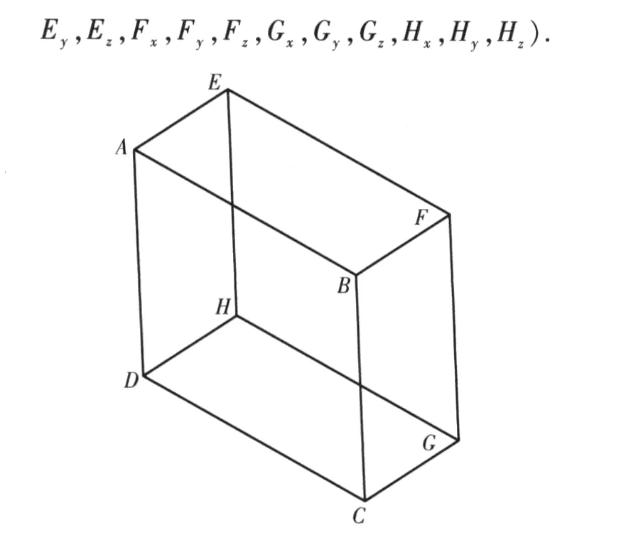
Fig.1 Model of RPP
Considering that it is not difficult to convert a data format to another,and the application of the proposed model may not be affected,also,in order to simplify the calculation and reduce the unnecessary modification for the existed damage simulation system,the description model used in Ref.[7]can be selected.
Figure 2 shows the model of a RPP used in this paper,it can be described as
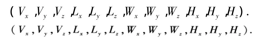
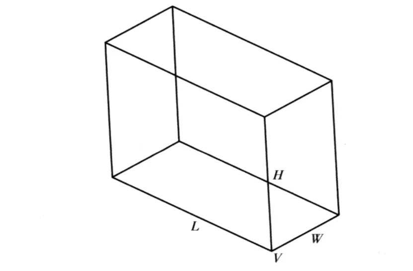
Fig.2 Model of RPP in this paperFigure 3 shows the model of a RCC used in this paper,it can be described as

The basic function of the interface is to extract the data from CAD data to satisfy the requirements of BDSS as described in Ref.[7].
Fig.3 Model of RCC in this paper
1.3 Logic Flow of Interface
DXF file records all geometry information and many kinds of attribute information.These original element data can be read easily.But,it does not record the most of topology information,for example,joints between point and line,line and line,point and surface,line and surface,surface and surface.Thus,they can't be transferred into basic geometry entity information simply.
The geometry elements in engineering drawing include point,line,circle,arc and connection area.Each element must satisfy the projection rules of alignment in length,justification in height and equality in width.They determine the shape of three-dimensional entity.And the size of the entity can be found out from the size label on drawing.Extracted the shape and size of each basic entity in drawing,through projection and size restrict process,the basic entity shape and the relation between them can be identified by using proper methods and the particular information necessary for description model can be obtained finally.Fig.4 is the logic flowchart of the data interface.
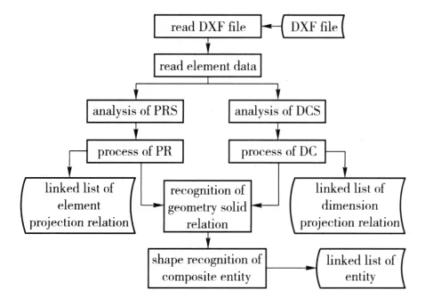
Fig.4 Logic flowchart of interface
1.4 Analysis of Projection Relationship Semantic(PRS)
1.4.1 Explicit Projection Semantic(EPS)
EPS is mainly used to identify the entities which do not intersect,tangent or truncate with others,and it focuses on the recognition of the projection characteristics of lines,planes and entities.
1)EPS of line type.The basic line type includes solid,dash,dot dash,sparse dash,etc.
2)EPS of line.The contours of ARB are all lines,and the projection of a linear may be just a point.
3)EPS of plane.A plane may be normal to a coordinate axis,therefore,its projection may be a linear.
4)EPS of basic entity.Table 1 shows the EPS of some basic entities.It can be seen that the EPSs of basic entities are mostly on the basis of dot dash lines.
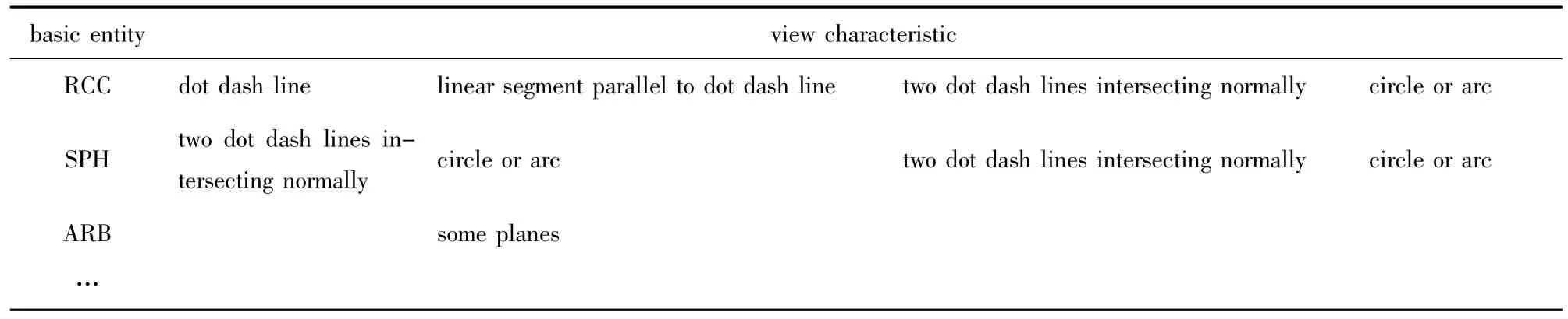
Table 1 EPS of general basic entities
1.4.2 Implicit Projection Semantic(IPS)
If an entity does not intersect with other entities,it can be identified easily by EPS.But,the intersecting of entities is difficult to avoid,which will increase the complexity of identifying entity. However, the combination of entities will leave obvious mark,which can be captured by using the projection rules of point,line,circle and arc.
1)General IPS.There are enriched of IPS in points,the general IPS can be obtained by classifying the points,Table 1 is the classification of points.
2)IPS of entity relationship.Intersection and tangent are the basic relationship between two entities.For example,when a tangential point appears,if there is a floating point or hollow point,the tangent of a plane and a curve suface may be identified,while an extrme point may mean an intersection of entities.
1.5 Analysis of Dimension Constraint Semantic(DCS)
DRS can be classified to two categories,the explicit dimension semantic(EDS)and implicit dimension semantic(IDS).
1.5.1 Explicit Dimension Semantic(EDS)
Every dimension exists as a figure element in CAD data model.For example,the linear dimension semantic can be expressed as 1)A dimension consists of line,boundary line,text and arrowhead;2)The dimension line and boundary line are generally thin solid line;3)The dimension line is parallel with marked dimension,the dimension boundary line is derived from extension line,axis of drawing,or the extension line and axis is used as the gap directly;4)Generally,the prefix of a dimension text can be used to distinguish it with others.For example,Φ means the diameter,R means the radius,and SR may be a SPH.
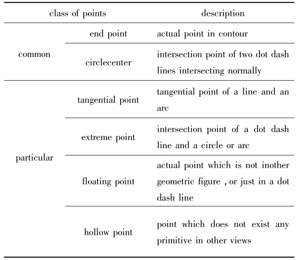
Table 2 Classification of points in IPS
1.5.2 Implicit Dimension Semantic(IDS)
IDS reveal the relationship between the dimension and graph,the dimension constraint semantic can be reflected only when a primitive is directly limited by a dimension.If a structure is not directly limited by a dimension,and an indirect restriction through projection does not exist,IDS must exist.It may consist of 1)transition,distributing character;2)symmetry structure;3)dimension function semantic.
1.6 Projection Relation(PR)
1.6.1 Mergence and Break of Graph Elements
In a DXF file,each graph element is not organized in a certain order,thus,the data from a DXF file can not directly applied to recognize the entities.In addition,during the generation of orthographic views,a lot of mergence and break of primitives,such as lines,points and arcs,etc.,will be formed,which will make the entity recognition more difficult.For example,in Fig.5,line AB is broken as AC,CD and DB,and they must all be added to the primitive list.As for arc ACB and ADB,they should be merged as a circle.
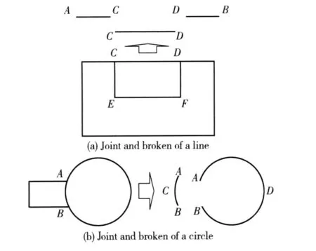
Fig.5 Mergence and break of graph elements
1.6.2 Extraction of Connected Regions
The minimum connected region generally corresponds to a mapping area of the surface(curved and plane)of an actual object on a projection plane.Through searching of all connected regions in each view,the projection area's explicit expression of the surface of an object in engineering drawings can be obtained.
Viewing from the direction of projection,some part's surfaces expressed in a view may be invisible,and their outline will be expressed as dash lines.This kind of invisible two dimension area can be called as hidden surface,while the visible area can be the real surface.Considered that a hidden surface may intersect with a real surface,we must process all minimum connection regions which consist of solid lines,dash lines,and both solid and dashed lines must be processed when we extract them from graph data.
1.6.3 Projection Relation Chain
The basic principle to set up the projection relation chains is the coordinate matching for each view.For example:1)point to point,the point in a three dimensional space can be obtained by coordinate matching for points;2)point to line,mainly process a dot dash line which represents an axis and an intersection point of two dash lines,which represents a circular center position;3)line to line,the corresponding relation of lines in three dimensional coordinate,etc.can be processed.
1.7 Dimension Constraint(DC)
From the function of dimensions,they can be divided into 3 kinds,shape dimension,position dimension and global dimension.At the aspect of two-dimension,they can be considered as the point,line,and arc to limit the graph.In order to make the dimension constraint fully play in recognition of entities,some primitives relative to the graph should be recorded,such as the extension lines of a linear dimension,the circular element and line element of a diameter,etc.After that,a dimension constraint chain to organize and describe the relationship between the dimension constraint and primitives can be set up.In this chain,we can make the extension lines be index and indicate to the graph element relative to the dimension.Especially,from the dimension type,we can make use of the prefix of a dimension more efficiently to search the primitives.
1.8 Recognition of Geometry Relation
Firstly,search the free primitives.All primitives will be searched,and the primitives which are not explicitly restricted by the dimensions in the projection relation chain,dimension tree and dimension constraint chain will be found out.These primitives are called as free primitives,including free point,line,circular,arc and connection region.
Secondly,the entity relationship can be determined on the basis of free primitives.
Thirdly,the entity relationship can be judged on the basis of characteristic point.The end point of intersecting line is called as the characteristic point.From the connection region that the characteristic point belongs to,the judge rules can be described as follows:1)If it is a concave point,then two intersecting entities are all real entity;2)If it is a convex point,then two intersecting entities are all hidden entities.
1.9 Shape Recognition of Composite Entity
For the simple entity that does not compose with others,it can be easily recognized through totally con-nection region matching.But in fact,the composite entity is more common.The recognition of composite entity is rather complicated because of its incomplete projection.Due to limited space,it is not discussed in detail.
2 Implementation and Application
2.1 Basic Algorithm
According to the basic principle mentioned above,some basic algorithms can be set up.For example,the algorithm for reading DXF file can be described as the follows.
1)Open the DXF files in text file format.
2)Find location record as“Entities”,if not find,then end.
3)Read a record.
4)Judge the record's content.
If it is“ENDSEC”,then end.If it is AcDbLine,AcDbCircle,etc.,then read the relative line data.If it is AcDbDemension,then read the dimension data.
5)Return to 3).
Data of each line element or dimension will be stored in a special element linked list.
The algorithm for the line's break can be written as the follows.
1)Read a line segment(AiBi)from the element link list.Its start and end points are Aiand Bi.
2)Calculate all intersection points of all other line segments with AiBiand put them to intersection list.Suppose there are n points totally,and express them as

3)According to the distances of all points to Ai,rank them increasingly.For description convenience,the ranked point list can be expressed as Eq.(1)also,and the broken line segment AiBiis

4)Return to 1),until all line segments have been broken.
2.2 Implementation
After software analysis and design,a special program was developed in Microsoft VC++6.0 and SQL Server 2000.It can extract data from DXF file and translate it to another data format which is used in other software named as vehicle battlefield damage simulation system(VBDS).And it is integrated to VBDS and becomes an important module of it.There are three main lists to store entity data in VBDS.
1)Unit list for name,number and the description of basic items.
2)Element list for its number,material,operation expression and the unit it belongs to.
3)Entity list for its number,type,geometry parameters,etc.
2.3 Application
Figure 6 is the front view of a simplified gear box of a vehicle.Fig.7 shows the program interface and running result.
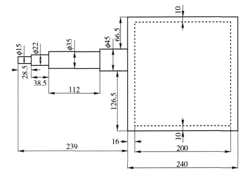
Fig.6 Front view of gear box shell and first axis
1)Six entities(No.1 to 6)are extracted from CAD data by the program successfully.
2)Five elements(No.1 to 5)and two units(first axis and box shell)are set up manually.
3)The entities 1,2,3 and 6 are RCCs.They are all real entities.
4)The entities 4 and 5 are RPPs.4 is a real entity,5 is a virtual entity,and their relation is 4 - 5.They form the box shell.
After data extraction,shot-line analysis can be carried out for the gear box.In the analysis,a point explosive model can be used.The explosive point is(1 000 mm,1 000 mm,0 mm),the elevation is[0°,180°]with the step of 5°,and the azimuth is [0°,360°]with the step 5°also.
3 Discussions
Through systematic analysis and research,a new method to apply the CAD data to target description system is presented,and an interface model between CAD data and TDS is developed.The practical application indicates that the data interface model is feasible,and it can complete the basic data extraction and transformation and provide a technical support for a utility interface.
There are still some problems in this model,for example,the element and unit data can't be extracted from CAD model,it is more proper for simple CAD model,etc.The research should be carried out more deeply.
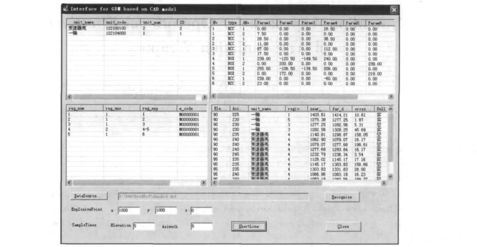
Fig.7 Program interface
[1]Butler Lee A,Edwards Eric W,Kregel Dwayne L.BRLCAD tutorial series:volumeⅢ-principles of effective modeling[M].MD:U.S.Army Research Laboratories,2003:5.
[2]LIU Xiang-kai,TANG Yan-feng,WANG Jia-ning,et al.A study on an interface between CAD model and geometry description model of materiel[J].Beijing:Acta Armamentarii,2007,28(1):115 -118.(in Chinese)
[3]AutoCAD 2011,DXF Reference[M/OL].CA:Autodesk Inc,2010,http:∥ images.autodesk.com/adsk/files/acad_dxf2.pdf.
[4]Kaplan Bruce J,Wallick D Jerry.ABDR analysis methodology development requiremrnts[R].VA:Logistic Management Institute,ADA304294,1994:1-25.
[5]Bain Lawrence W,Jr Reisinger Mathew J.The gift code user manual[R].VolumeⅠ.Introduction and Input Requirements.MD:U.S.Army Ballistic Research Laboratories,1975:1 -60.
[6]ZHENG Zhen-zhong.Battle damage conspectus for armored vehicle[M].Beijing:The Publishing House of Ordnance Industry,2004:186-188.(in Chinese)
[7]LIU Xiang-kai.Study on battle damage simulation model for materiel[D].Shijiazhuang:Academy of Ordnance Engineering,2001:1-88.(in Chinese)
[8]Muuss Michael J.GED:an interactive solid modeling system for vulnerability assessment[R].MD:U.S.Army Ballistic Research Laboratories,ADA126657,1983:1 -69.
[9]Butler Lee A,Edwards Eric W,Schueler Betty J,et al.BRL-CAD tutorialseries:volumeⅡ-introduction to MGED[M].MD:U.S.Army Research Laboratories,2001:259-265.
杂志排行

Defence Technology的其它文章
- Modeling and Simulation for Complex Repairable System with Built-in Test Equipment
- A New Synthesis Method for Sum and Difference Beam Pattern with Low Sidelobe
- An Evaluation Approach for Operational Effectiveness of Anti-radiation Weapon
- An Orthogonal Wavelet Transform Fractionally Spaced Blind Equalization Algorithm Based on the Optimization of Genetic Algorithm
- Prefix Subsection Matching Binary Algorithm in Passive RFID System
- Research on Performance of U Separator in Sand and Dust Test System