STATE CORRECTION EQUIPMENT OF WORK-PIECE BASED ON MACHINE VISION
2011-02-20CAIChenyunLIXia
CAI Chen-yun, LI Xia
(School of Electrical and Information Engineering, Shaanxi University of Science & Technology, Xi′an 710021, China)
0 Introduction
This paper presents a novel work-piece state correction equipment which is in serial production. The work-piece has a unique property which has a screw hole off the axis neutrally; the hexagon work-piece is a kind of special parts in the line. According to the technique, before the next assemble it has to be put in the same state orderliness. This equipment offers four features. First, it works using image processing which never appeared in such type of application. Similarly, it can control the work-piece into middle of the conveyor. Third, it can put work-piece in the same state quickly. Finally, it allows a various speed of the conveyor. Current equipment which has the state correction function usually is the combination of sensors and machinery. Such type of equipments usually is developed to fit a simply situation and constantly speed of conveyor. Our equipment can fit a multi-purpose situation because not only it uses image processing but also it can adjust algorithm flexibly. Flexible algorithm applies vivid application situation.
1 Structure and Workflow of Equipment
This set of equipment (Fig.1) is mainly consisted of industrial computer, industrial camera, machine arm, conveyor, photoelectric switch, slope, and PCI interface card and PCI image capture card. Among them, the machine arm is consisted of a horizontal pole and a disk electromagnet. The electromagnet is located above the conveyor, can only allow a work-piece pass under. This electromagnet can take the vertical axis as center to revolve under the control of computer. The camera is a black and white camera and sends video signal to video card through coaxial cable. PCI interface card cennects sensors and performing structure to computer through shielded twisted-pair. PCI interface card is responsible to receive feedback signal of machine arm and the photoelectric switch signal, in the meantime, it also sends out the order signal of computer to the performance structure of machine arm. The conveyor takes a high contract material from work-piece color, in order to detecte clear shape of object. There is an important and essential element in this equipments. it is a slope. This slope has 2 functions: the first is mechanical concentration function, the second is acceleration function.Through the two functions, slpoe can take advantage of the two functions in order to make work-pieces slip into the center axis of conveyor, in the meantime it promotes the computing speed and accuracy.
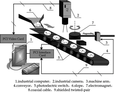
Fig.1 Structure of equipment
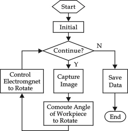
Fig.2 Main flowchart of equipment
Fig.2 shows the main flowchart of equipment. The work-piece slips into conveyor one by one in order. When work-piece moves under the camera, the computer will succeed in recieving a camera video stream signal and acquire a series of images thus. The computer carries on images proccessing of current work-piece in order to comput deviation angle. As the work-piece continuously moves, examine continuously gose on. When work-piece moves under the camera, the photoelectric switch will be covered by the work piece and delivers an switch signal to the computer. This action means the work-piece has already arrived under the electromagnet. After receives a switch signal, the computer sends out a control signal to the machine arm, then the electromagnet powers on and adsorbs a work-piece. The electromagnet revolves to correct a work-piece state. When this action has been completed, electromagnet powers off to release work-piece. This process circularly carries on, work-pieces will be corrected one by one in the same direction alignment and be deliverered to next procedure.
2 Key Issues
As the reason of image characteristic, only when object moves under camera, the error of capturing will be the minimum. But the difficulty of capture image is how to judge the movement when the work-piece moves under the camera. This set of equipment needs to solve two key issues. The first is when the computer succeeds in capturing a suitable image; the second is how can compute deviating angle of a testing work-piece. According to current profiles, location algorithm of image is majorly making the basis of pattern recognition. These methods can meet the purpose of the object recognition and the location position, but they have a common problerm, the low computing efficiency. For the low efficiency problerm, static object doesn′t have influence too much, but when object moves fastly on the conveyor, it brings disadvantages for realtime calculate and examination. In the mean time linear classifier, neural network algorithm, signature matching algorithm need too much data for repeatedly training. This takes a great deal of consume of operation cost. In fact, on-line products usually changes, computer can not carry on a great deal of training. So have to use a kind of simple, effective and dependable calculate way to meet the state correction purpose. Discrepancy measures for binary images were proposed[1-4]. Those methods use the distance between the mis-segmented pixel and the nearest pixel that actually belongs to the mis-segmented class. Then a discrepancy measure is calculated. However, those methods cannot apply to grey-scale and colour images. Dissimilarity measures were proposed[5,6]. Those measures evaluate dissimilarities between objects in grey-scale images. Since those methods aim at derivation of a difference between objects, they are inapplicable to labeled image evaluation by pixel-based labelling such as color clustering. Similarity measures for images were proposed[7-10]. Those methods characterize different segmentation algorithm by simply computing some “goodness” measures based on the segmented image without the knowledge of the correct segmentation.
3 Solution of Issues
Let A and B be labelled images. Suppose that the size of the two images is the same, and letNbe the total number of pixels in each image. The purpose of the similarity measure is to bring an idea of the error amount introduced by the binary relations between arbitrary pixels. So, first of all, a coincidence value of binary relationSis calculated for each pair of pixels (i,j); 1≤i,j≤Nby the following equation:
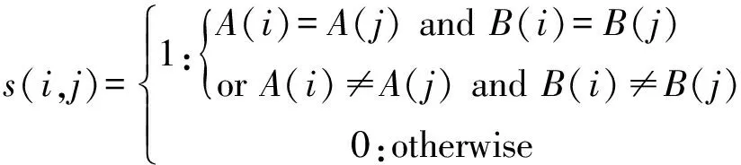
(1)
WhereA(i) denotes a label value assigned to a pixelion the image A. Although the order of pixels is free, the same order is required between two images. Thus, the same number of pixeli,j,... points out the pixel of the same state for two images. Fig.3 shows examples in the cases(i,j)=1 in Eq.(1). If both pixelsiandjhave the same label for both two images as shown in Fig.3, the coincidence value of binary relations must be high. In the same concept, if both labels have the different label for both two images as shown in Fig.4, the coincidence value must be high. Thus, in the above two cases,s(i,j)=1 . On the other hand, if the label of a pixel coincides with another pixel′s label on an image and the labels are difference on another image,s(i,j)=0 as shown in Fig.5.
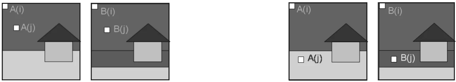
Fig.3 Both pixels have been assigned to the same label. In the case s(i, j)=1 in Eq.(1) Fig.4 Two pixels have been assigned to the different label. In the case s(i, j)=1 in Eq.(1)

Fig.5 Two pixels have been assigned to the different label. In the case s(i, j)=0 in Eq.(1)
Then a coincidence matrixSis represented by
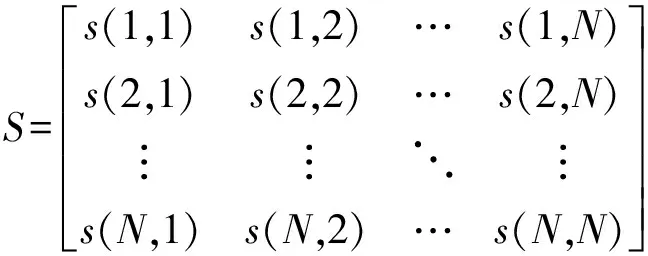
(2)
The coincidence values(i,j) has a commutative relations(i,j) =s(j,i), wheres(i,i)=1. Thus, Eq.(2) is modified as and it becomes a symmetric matrix. Then the proposed basic similarity ratesimis defined the average of upper triangular elements of matrixSas follows:
(3)
Where the denominator represents the number of upper triangular elements. The similarity ratesimbecomes 1 when two labelled images are the same completely. If an unique label is assigned to an image and altogether different labels are attached to another image, the similarity rate becomes 0.
The flowchart of capture image is shown in Fig.6. The computer is responsible for processing video signal, receiving video signal from the camera, and capturing the images from which the PCI video is installed in the computer. The image will be transformed into binary image, in order to carry on similarity rate calculation. It is the key moment, when a similarity rate becomes the maximum at the same time work-piece moves under camera. Therefore computer will output current image for next processing at this moment. Grey level transformation (Fig.7) is to convert image into a binary image. For it only uses the shape character of image, algorithm will take advantage of binary image transformation. Let original image (a) transform to binary image (c) using transformation curve (b) which is referred from grey histogram.
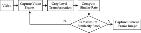
Fig.6 Flowchart of capture image
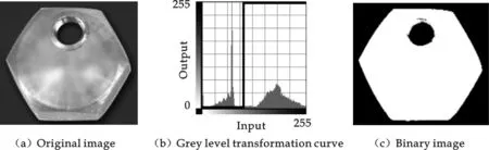
Fig.7 Grey level transformation

Fig.8 Labelled image matching
In this application, let A be the input image and B be the labelled image (Fig.8). As work-piece′s shape is a hexagon , a circle is suitable for image B. The circle is located the place where is under camera. When work-piece moves under the camera, the similarity ratesimwill approach to 1 and become the maximum. Computer will let transport current work-piece′s image to next processing at this moment.
The difficulty of computing deviate angle lies in how to quickly compute. Currently the calculation of object shape parameter are two-dimensional calculation and 3D calculation of shape detection, the former mainly uses the operation method of morphologic characters that appears opposite and simple, the latter uses 3D affine transformation and morphologic operation for a combining method, so the amount of calculation of the latter is bigger. But it doesn′t have a kind of method for unifying to various different application situations, so we have to develop a kind of quickly effective method. For the application environment, because of object shape is relatively simple, and the character of object is mainly expressed its upper surface characteristic, so we decide to use morphologic operation and geometry operation together. Geometry shape operation is relatively simpler than others, so this method can satisfy the request.
Fig.9 shows the method of how to calculate the deviate angles of work-piece. Note full line hexagon is a “Golden” image (a standard image of work-piece which is in corrected state), note dash line hexagon is the test image (which is waiting for correction).A(x1,y1) is the image G-center (gravity center) of screw hole in full line hexagon.B(x2,y2) is the image G-center (gravity center) of screw hole in dash line hexagon.O(x3,y3) is the center of hexagon. Angleθis deviation angle of testing work-piece. Three points includeA(x1,y1),B(x2,y2) andO(x3,y3), noteRas radius. Among them,A(x1,y1),O(x3,y3) andRhave been already known , test image hole′s G-center computesB(x2,y2).Now we can easily build a way to compute angleθusing three points.
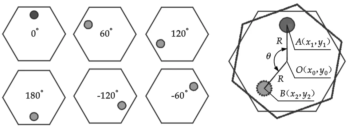
Fig.9 Method of calculating the deviate angles
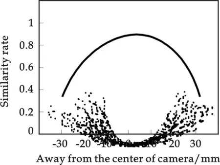
Fig.10 Similarity rate sim
4 Location Accuracy
It is different of location error between similarity rate way and linear classifier in 1 000 work-pieces testing. Fig.10. shows similarity ratesimwill approach to 1 and become the maximum when work-piece moves under camera, dash line indicates the trend of similarity ratesim. Horizontal axis is the away from center camera crossing moving direction, vertical axis is the similarity ratesim.
For the sake of using linear classifier, we defined 8 character points and 24 character shapes. Some researches[11-14]show the error times of linear classifier is bigger than the method of similarity rate. This is because linear classifier′s accuracy is affected by the numbers of character parameters. On the other hand, linear classifier needs to be training, but it is not realistic in such application.
[1] W.A.Yasnoff, J.K.Mui and J.Bacus. Error measures for scene segmentation[J]. Pattern Recognition,1977,9(4):217-231.
[2] T.Peli, D.Malah. A study of edge detection algorithms[J]. Comput. Graphics Image Process.,1982,20:1-21.
[3] W.Pratt. Digital image processing[M]. New York:Wiley-Interscience,1991.
[4] R.-R. Ramon. A measure of quality for evaluating methods of segmentation and edge detection[J]. Pattern recognition, 2001,34:969-980.
[5] Di Gesu, V. and Starovoitov, V. Distance-based functions for image comparison[J]. Pattern Recognition Letters, 1999, 20:207-214.
[6] D.Coquin and Ph.Bolon. Application of Baddeley′s distance to dissimilarity measurement between gray scale images[J]. Pattern Recognition Letters, 2001, 22:1 483-1 502.
[7] M.D.Levine and A.Nazif. Dynamic measurement of computer generated image segmentations[J]. IEEE Trans. PAMI-7, 1985:155-164.
[8] A.M.Nazif and M.D.Levine. Low level image segmentation: an expert system[J]. IEEE Trans. PAMI-6,1984: 555-577.
[9] Y.J.Zhang and J.J.Gerbrands. Objective and quantitative segmentation evaluation and comparison[J]. Signal Processing, 1994, 39:43-54.
[10] W.A.Yasnoff and J.W.Bacus. Scene segmentation algorithm development using error measures[J]. AOCH, 1984,6:45-58.
[11] S. Subbarayan, K. Kim, M. T. Manry,etal. Modular neural network architecture using piecewise linear mapping[J]. 30th Asilomar Conference on Signals, Systems & Computers, 1996, 2(11):1 171-1 175.
[12] W. Li, J.-N. Lin, R. Unbehauen. Canonical representation of piecewise polynomial functions with nondegenerate linear domain partitions[J]. IEEE Trans. Circuits and Systems I: Fundamental Theory and Applications, 1998, 45(8):838-848.
[13] D.R. Hush and B. Horne. Efficient algorithms for function approximation with piecewise linear sigmoidal networks[J]. IEEE Trans. Neural Networks, 1998,9(6):1 129-1 141.
[14] E.F. Gad, A.F. Atiya, S. Shaheen,etal. A new algorithm for learning in pieceswise-linear neural networks[J]. IEEE Trans.Neural Networks, 2000, 11(8): 485-505.
