A cryogenic radio-frequency ion trap for a 40Ca+optical clock
2023-12-02MengyanZeng曾孟彦YaoHuang黄垚BaolinZhang张宝林ZixiaoMa马子晓YanmeiHao郝艳梅RumingHu胡如明HuaqingZhang张华青HuaGuan管桦andKelinGao高克林
Mengyan Zeng(曾孟彦), Yao Huang(黄垚), Baolin Zhang(张宝林),Zixiao Ma(马子晓),4, Yanmei Hao(郝艳梅),4, Ruming Hu(胡如明),4,Huaqing Zhang(张华青), Hua Guan(管桦),5,‡, and Kelin Gao(高克林),§
1Huazhong University of Science and Technology,Wuhan 430074,China
2State Key Laboratory of Magnetic Resonance and Atomic and Molecular Physics,Innovation Academy for Precision Measurement Science and Technology,Chinese Academy of Sciences,Wuhan 430071,China
3Key Laboratory of Atomic Frequency Standards,Innovation Academy for Precision Measurement Science and Technology,Chinese Academy of Sciences,Wuhan 430071,China
4University of Chinese Academy of Sciences,Beijing 100049,China
5Wuhan Institute of Quantum Technology,Wuhan 430206,China
Keywords: cryogenics,ion trapping, 40Ca+optical clock
1.Introduction
In recent decades, significant progress has been made towards the high accuracy and stability of single-ion optical clocks[1–4]and optical lattice clocks.[5–8]Optical clocks referenced to Al+,[2]Yb,[5]Sr,[6–8]Yb+[3]and Ca+[1]have reached a fractional frequency uncertainty of 10-18or even better.Such an uncertainty is already two orders of magnitude smaller than the uncertainty of microwave clocks,[9]so optical clocks will promote not only a redefinition of the second[9,10]but also applications such as frequency metrology and fundamental physics.[11]In many state-of-the-art optical clocks, the Stark shift uncertainty due to blackbody radiation(BBR) remains the dominant contributor to the overall clock uncertainty.[1,5–8]One way to reduce the BBR shift uncertainty to 10-18or even less is to ensure a uniform, accurately characterized BBR environment for the ions/atoms at room temperature, such as the Yb clock at NIST[5]and the Sr clock at JILA.[7]These methods reduce the uncertainty of the BBR shift by accurately evaluating the BBR temperature felt by the ions/atoms, but do not suppress the BBR shift.Another way to simultaneously reduce the BBR shift and its uncertainty is to interrogate the ions/atoms in a cryogenic environment.In addition, the cryogenic environment can produce a much higher vacuum level, which reduces the background gas collision rate, thus benefiting both the storage and the spectroscopic study of atoms or ions.[21–24]A cryogenic environment has been used in the Hg+[12]and Ca+[1]optical clocks, the highly charged ion optical clock[13]and the Sr optical lattice clock,[6]among others, and greatly suppresses the BBR shift and its uncertainty.
Building optical clocks based on40Ca+gives technological advantages over other optical clocks in that all the wavelengths required for laser cooling and state manipulation can be generated by commercially available and easy-to-handle solid state lasers.For40Ca+optical clocks, BBR can induce the Stark shift of∼0.35 Hz at room temperature.[26–28]The uncertainty from this frequency shift also dominates the uncertainty budget table of a Ca+optical clock.It scales proportionally with the fourth power of the ambient temperature(T4)[29,30]
The BBR Stark shift of the clock transition is reduced to the mHz level when Ca+optical clocks are interrogated in a liquid-nitrogen environment of approximately 77 K.[1]In this case,if the BBR temperature can be estimated with uncertainties of a few K, the uncertainty of the BBR shift can be estimated to be<10-18.In contrast to liquid-nitrogen refrigeration, a mechanical cryocooler or a liquid-helium cryostat is used in some optical clocks to achieve lower-vacuum cryogenic environments.[6,13,31]However,the vibrations generated by these methods must be suppressed at the position of the ion trap,[19,31]which increases the system complexity.For40Ca+ion optical clocks, liquid-nitrogen cooling is good enough to suppress the BBR frequency shift and has a lower cost.
In previous work we built a liquid-nitrogen-cooled40Ca+optical clock(cryogenic trap 1),and its systematic uncertainty was estimated to be 3.0×10⁻¹⁸.[1]However,cryogenic trap 1 requires a daily replenishment of liquid nitrogen because the liquid nitrogen is depleted about 36 h after the liquid-nitrogen container is filled.The process of replenishing the liquid nitrogen causes a short-term loss of the fluorescence signal for 15 min, and it takes more than 1 h to return to the normal operation.Moreover, due to the large size of the system and the overall performance of the magnetic shielding in cryogenic trap 1, the magnetic field fluctuation at the ion is larger than that of room temperature optical clocks with good magneticfield shielding,broadening the spectral line of the clock transition.The magnetic field fluctuation in the vertical direction of cryogenic trap 1 is much stronger than that in the horizontal direction,resulting in the need to set the magnetic field direction to horizontal during the clock interrogation process, so that the overall magnetic field amplitude is less sensitive to the vertical environmental magnetic field fluctuations.All of the above means that although cryogenic trap 1 has a lower system uncertainty than room-temperature40Ca+optical clocks,it does not perform as well as those room-temperature optical clocks in terms of stability.[1,26,32]
For the above reasons, we started to design and build a new generation of cryogenic ion trap for40Ca+optical clocks(cryogenic trap 2)with longer continuous operating time and better control of the ambient magnetic field.In this work,the continuous operating time was extended to more than 5 days by increasing the volume of the liquid-nitrogen container,and the problem of recovery of the ion fluorescence signal after liquid-nitrogen replenishment was optimized.At the same time,by improving the design of the magnetic shields and using a titanium vacuum chamber, the magnetic field noise at the ion is effectively suppressed, and a narrower spectral line in the clock interrogation is obtained.With these improvements, the cryogenic40Ca+optical clock will have a longer continuous operating time and better operating conditions in the future.
This article will begin with an overview of this improved liquid-nitrogen system, then the liquid-nitrogen setup and BBR shield,ion trap and electrodes and the magnetic control system will be introduced in detail in the subsequent sections.
2.External design of the improved liquidnitrogen system
2.1.Vacuum system
The ion trap,the BBR shield and the liquid-nitrogen container are housed in a vacuum chamber.The chambers and associated fixtures are made of titanium metal,which has nonmagnetic properties and lower outgassing rates, aiming for smaller shifts caused by the magnetic field and ultra-high vacuum maintenance.Optical and electrical access is provided by ten ports, seven of which are used for laser access along three orthogonal directions and fluorescence collection, and two of which are used for electrical feedthroughs.A composite pump,combining the non-evaporable getter pump with the ion pump, is connected to the last port, with a pumping speed of more than 500 l·s-1(H2).Compared with our previous stainless-steel system,[1]where only a diode ion pump with 6 l·s-1(Ar)and 15 l·s-1(CH4)was available,a StarCell ion pump (Agilent Technologies) with 21 l·s-1for Ar and 30 l·s-1for CH4was installed in the new system.With this improvement, the background gas pressure has been reduced to 4×10⁻⁹Pa.An ideal cryogenic vacuum environment not only helps to reduce the effects of collisions between trapped ions and background gases but also to prevent ion loss by reaction with gases that produce new molecular ions.AC and DC magnetic fields from the laboratory environment are suppressed by six concentric permalloy metal magnetic shields outside the vacuum chamber.To precisely control the magnetic field felt by the ion, three pairs of Helmholtz coils are mounted on the laser beam access port (the pink parts in Fig.1).The vacuum system is mounted on an optical table,where the laser setup rests.
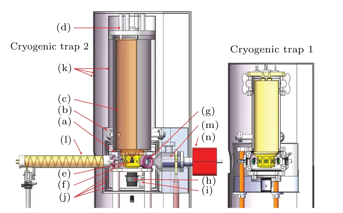
Fig.1.Cutaway drawing of the cryogenic system.The left panel shows cryogenic trap 2 and the right panel shows the main vacuum system part of cryogenic trap 1 at the same scale.Notable features include: (a) vacuum cambers;(b)polytetrafluoroethylene fixing rods(assembled with three pieces);(c)liquid-nitrogen container;(d)supplemental port and pressure relief ports of liquid nitrogen (assembled with four pieces); (e) BBR shield;(f)ion trap;(g)frames of Helmholtz coils(assembled with three pairs);(h)imaging system; (i)wires of the ion trap electrodes; (j)three-layer internal magnetic shields; (k) three layers of external magnetic shields; (l) helical resonator;(m)non-evaporable getter pump;(n)ion pump.
2.2.Imaging system
The fluorescence of the40Ca+ions at the cooling transition at 397 nm is split at a ratio of 1:9 to image onto an electron-multiplying CCD camera(Andor)and a photomultiplier tube (PMT; Hamamatsu), respectively.The first imaging lens consists of two custom-made aspherical lenses (Asphericon) mounted below the re-entrant viewport at the bottom of the titanium vacuum chamber.It has a free aperture diameter of 50 mm and a working distance of 48.3 mm.With a numerical aperture of 0.46,it covers 5.6%of the total solid angle around the ion.After the ion fluorescence collection, a 40× achromatic microspot ultraviolet focusing objective (Thorlabs) magnifies the secondary image onto the CCD camera and PMT.A 100µm pinhole placed in front of the objectives is centered on the ion image with micrometer screws to maximize the fluorescence-to-background ratio.The collimated light passes through a series of baffles and two narrowbandpass filters(Semrock)to prevent stray light from the other laser sources from reaching the PMT and CCD.After Ramsey excitation,the PMT monitors the final state of the ion after interrogation by observing the ion fluorescence at 397 nm.This method is known as‘electron shelving’.[46]Single-ion fluorescence rates of 200 counts·s-1were typically observed during a 0.5 ms long detection with scattered background light levels of less than 20 counts·s-1.After the interrogation, the ion is initialized again with the 854 nm laser, making the clock run faster.The CCD camera is used to simultaneously observe the ion’s motion and position.
3.Liquid-nitrogen setup and BBR shield
The cryogenic quadrupole Paul traps are used in several laboratories around the world to achieve extremely low pressures[21,24]or to reduce BBR shifts in optical clocks.[1,6,12,13]As shown in Fig.2, the ion trap assembly and the BBR shield are closely connected to the bottom of the liquid-nitrogen container.To achieve low differential contraction between the parts when the section is cooled to liquidnitrogen temperature, both the BBR shield and the container are made of oxygen-free copper with good thermal conductivity.The ultrahigh vacuum provides good insulation between the cryogenic section and the room-temperature vacuum chamber,except for a few necessary electrical connections and the end of the three polytetrafluoroethylene fixing rods.These designs can ensure the stability and uniformity of the temperature of the ion environment,which then benefits the frequency uncertainty and long-term stability of optical clocks.
The liquid-nitrogen container is rigidly connected directly to the top flange of the vacuum system through four nonmagnetic stainless steel vent holes to reduce heat transfer between the liquid-nitrogen container and the room-temperature vacuum chamber, replacing the previous elastic connection method[1]using stainless steel flanged bellows.Two of the vent holes are used for liquid-nitrogen evaporation and liquidnitrogen replenishment,and two others are sealed with rubber plugs.The change in the nitrogen output from the vents may indicate the change in the ion trap position, so it is helpful to monitor the nitrogen flow through the vents with a flow meter.

Fig.2.Schematic diagram of the cryogenic section assembly showing the liquid-nitrogen container and the BBR shield.The liquid-nitrogen container is approximately 640 mm high and 5 mm thick.It has a liquidnitrogen capacity of ∼15 l,which is three times that of cryogenic trap 1.The pressure relief ports for liquid-nitrogen replenishment have been increased to four compared with the previous design.In order to reduce the displacement of the ion trap after each round of liquid-nitrogen replenishment,they are symmetrically distributed on the top of the liquidnitrogen container.Based on similar considerations,three polytetrafluoroethylene rods are fixed in the lower half of the liquid-nitrogen container to prevent horizontal displacement.Finally,cryogenic trap 2 can achieve continuous operation for up to 5 days without liquid-nitrogen replenishment.
In our previous work,the liquid-nitrogen was completely consumed approximately 30 h after the liquid-nitrogen container was filled.[1]The ion-trap-position recovery process after each round of liquid-nitrogen replenishment caused the experiment to be interrupted for approximately 1.5 h every day.As shown in Fig.3,the horizontal displacement of the ion trap after the liquid-nitrogen replenishment causes the ion image observed by the CCD camera to initially disappear from the screen.Then,as the temperature distribution of the cryogenic section stabilizes, the ion trap center gradually returns to a level that is not much different from the initial position.This process takes more than 1 h, after which the PMT position is optimized to return the single-ion fluorescence-to-background ratio to normal experimental conditions.The stability of the single-ion fluorescence signal is critical for the clock interrogation and state detection,so in the design of cryogenic trap 2 we improved this situation by adopting better thermally conductive materials and fixation methods for the cryogenic section.Compared with the previous design,cryogenic trap 2 can return to the experimental state faster after liquid-nitrogen filling,and does not require daily liquid-nitrogen replenishment.We compared the CCD fluorescence image recovery capabilities of the two systems by recording the position of the ion image in the CCD before and after liquid-nitrogen replenishment,and the results are shown in Fig.3.
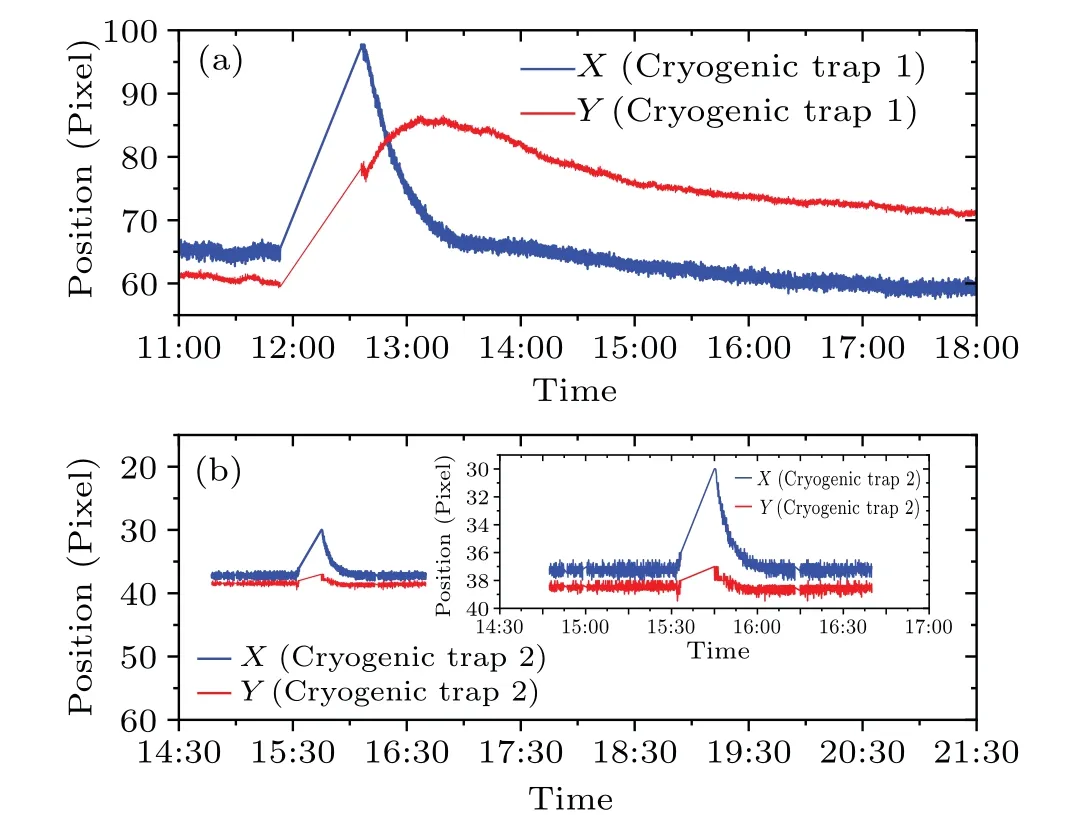
Fig.3.The precise ion position changes observed by the CCD camera.The X- and Y-axis displacements of the single-ion image in the CCD screen are recorded over time,characterizing the horizontal displacement of the ion trap.The interrupted part of the legend curve corresponds to the case when the ion displacement is beyond the imaging range of the CCD after filling with liquid nitrogen.It can be seen that under the same displacement–time coordinate scale,the ion imaging offset of cryogenic trap 2(bottom panel)is much smaller than that of cryogenic trap 1 (top panel) in both the X- and Y-axis directions,and the recovery time is much shorter.In addition,the ion imaging of cryogenic trap 1 has a small deviation from the initial position after returning to relative stability,requiring periodic optimization of the imaging system,while the ion imaging of cryogenic trap 2 basically returns to the initial position after 30 min and has a position drift of almost zero during the subsequent experiments.These improvements increase the continuous operating time of the liquid-nitrogen cryogenic40Ca+optical clock,so that the interruption time due to the liquid-nitrogen replenishment is only 30 min every 5 days, which contributes to the stability of the optical clock.
In the first cryogenic system, although the BBR shift is estimated to be 3.0±1.1 mHz, corresponding to a fractional uncertainty of 2.7×10⁻¹⁸,[1]it is still limited by the uncertainty of the environmental temperature felt by the ion.The uncertainty contribution from the differential static polarizability is less than 1×10-19, benefiting from a precise measurement through the magic trap frequency scheme.[28]While the contribution of the ambient temperature uncertainty has been greatly suppressed by reducing the ambient temperature from 293 K to 80 K, it is still too large to reduce the uncertainty to the 10-19level for the40Ca+optical clock.In the improved clock,more temperature sensors with 0.1 K calibration accuracy at liquid-nitrogen temperature are installed in the vacuum.The uncertainty of the temperature felt by the ion is aimed to decrease from approximately 5 K for cryogenic trap 1 to<3 K for cryogenic trap 2, corresponding to a BBR shift uncertainty of<6×10-19.
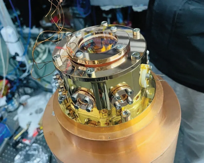
Fig.4.Physical illustration of the in-vacuum BBR shield.The BBR shield is attached to the bottom of the liquid-nitrogen container.Six BK7 glass windows of diameter 10 mm for light transmission are mounted on the sides of the BBR shield and one window of diameter 40 mm for both light transmission and fluorescence collection is installed at the bottom.The transmittance of the BK7 glass is zero for wavelengths>3µm,[36] which eliminates the effect of window transmittance on the BBR at room temperature.
4.Ion trap and electrodes
As shown in Fig.5, cryogenic trap 2 uses an ion trap of a similar design to the NIST one[37]and provides access ports for laser beams along three mutually orthogonal directions, making it possible to evaluate the micromotion shifts and the ion’s temperature with high accuracy.[2,4]The ion trap is built of a 0.3 mm thick diamond wafer, which is machined using the laser and then gold-plated to generate the radio-frequency (RF) trap electrodes and DC compensation electrodes.The distance between the trapped ion and RF electrodes is∼0.25 mm.The trap wafer is mounted on an oxygen-free copper support, which is attached to the bottom of the liquid-nitrogen container to achieve the cryogenic environment.The polished titanium endcaps are mounted on the oxygen-free copper support via two pieces of 0.8 mm thick diamond wafers, ensuring good heat transfer.Ions are generated by 532-nm laser ablation pulses focused on the surface of a calcium wire[33]mounted on the back of one of the endcap electrodes, approximately 8 mm from the trap center.Compared with the previous photoionization method in which atoms are emitted from a heated oven,[27]the laser ablation technique can reduce the heat load associated with ion loading,which is especially important for cryogenic systems.[21,34,35]The ion position in the axial direction of the trap is controlled by holding the endcap electrodes held at positive DC potential relative to the trap wafer.In the radial direction, the ion position is controlled with two mutually orthogonal DC compensation electrodes located 3 mm from the trap center.Based on measurements of the ion secular sideband spectra,the axial secular frequency is measured asωZ ≈2π×2.4 MHz and the radial secular frequencies areωX ≈2π×3.0 MHz,ωY ≈2π×2.8 MHz.

Fig.5.Trap geometry and laser beam layout are shown in the top view cross section (left panel).The schematic diagram in the upper right corner shows the ion trap used in the liquid-nitrogen clock.
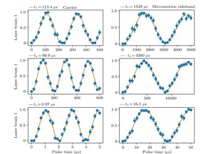
Fig.6.Rabi flopping on the carrier (left panel) and micromotion sideband (right panel) of the 40Ca+2S1/2–2D5/2 transition driven by the 729 nm probe laser beams in the three mutually orthogonal directions. tπ represents the Rabi π times for the carrier and the micromotion sideband at the same 729-nm power.The micromotion-induced shift can be evaluated by measuring the ratios of the sideband and carrier Rabi rates.[2,4,38] The uncertainties of the measured Rabi π time come from the statistical uncertainty of the Rabi-flop fittings.
The micromotion due to trap imperfections and the stray field is partially cancelled by optimizing the two compensation voltages.The micromotion is measured with the sideband-tocarrier intensity ratios method by probing the ion in three orthogonal directions.[4,38]If the micromotion levels are not optimal,the compensation voltages in the horizontal and vertical directions are adjusted and the measurement is repeated until an optimal solution is found.Figure 6 shows the Rabi oscillation of the carriers and the micromotion sidebands in three orthogonal directions after the micromotion has been optimized.With the introduction of the magic RF trapping frequency,where the second-order Doppler shift and the scalar Stark shift cancel each other,[28]the micromotion-induced shift can be greatly reduced.Experimentally, the trap is operated by applying low RF power(<2 W)at a frequency of 24.943 MHz(very close to the magic frequency of 24.801±2 MHz[28]),yielding an excess micromotion-induced shift uncertainty of<1×10-19.
5.Magnetic controlling system
In contrast to other ion systems being investigated, the single-ion40Ca+reference transition has a linear Zeeman sensitivity to the ambient magnetic field.The available qubit transitions of40Ca+have magnetic field dependences of up to 2π×39 GHz·T-1,[42,43]and the qubit transition has a linewidth of about 0.14 Hz.[44,45]When subjected to a magnetic field, the2S1/2–2D5/2transition splits into ten Zeeman components shifted symmetrically around the zero-field line center.[39]Probing several of them provides a scheme to cancel the main systematic effects such as the linear Zeeman shift and the electric-quadrupole shift.[40,41]While the first-order Zeeman shift can be cancelled by probing symmetric Zeeman components,the magnetic field fluctuation would broaden the observed clock transition, preventing the clock stability from being any better.
In previous work, a stable magnetic field environment was achieved using three pairs of Helmholtz coils and four layers of magnetic shields.[1]Since the vertical magnetic field fluctuation is much stronger than the horizontal magnetic field fluctuation in cryogenic trap 1, the magnetic field at the ions is compensated to zero by the Helmholtz coils inside the magnetic shields, and then a horizontal magnetic field of<3 µT is applied, so that the overall magnetic field amplitude is less sensitive to the vertical environmental magnetic field fluctuations.For our40Ca+optical clocks, prolonging the interrogation time is currently the dominant way to improve the stability; therefore, higher-performance clock lasers and better magnetic control systems are required for developing a stable lock with a narrower linewidth spectrum.
In the improved system,upgraded magnetic field control is used for cryogenic trap 2, providing better magnetic field stability and allowing the magnetic field to be controlled with higher precision.Three-layer inner and three-layer outer magnetic shields made of permalloy reduce the effects of slowly varying DC magnetic fields and strongly shield against the AC field broadening and shifts.What’s more, an active feedback control and passive compensation scheme has been introduced to suppress the magnetic field fluctuations,where the required passive compensation amplitude is obtained by monitoring the magnetic field fluctuations by the three-axis magnetic field sensors (Bartington) outside the magnetic shield.The compensation voltage obtained by the active feedback is applied to the pair of Helmholtz coils in the corresponding direction.After the above improvements,the magnetic field fluctuations at the ion position were spectroscopically measured using the servo locking results of cryogenic trap 1 and cryogenic trap 2,simultaneously.As shown in Fig.8, the measurement results show that the magnetic field noise stability of cryogenic trap 2 is about three times better than that of cryogenic trap 1.
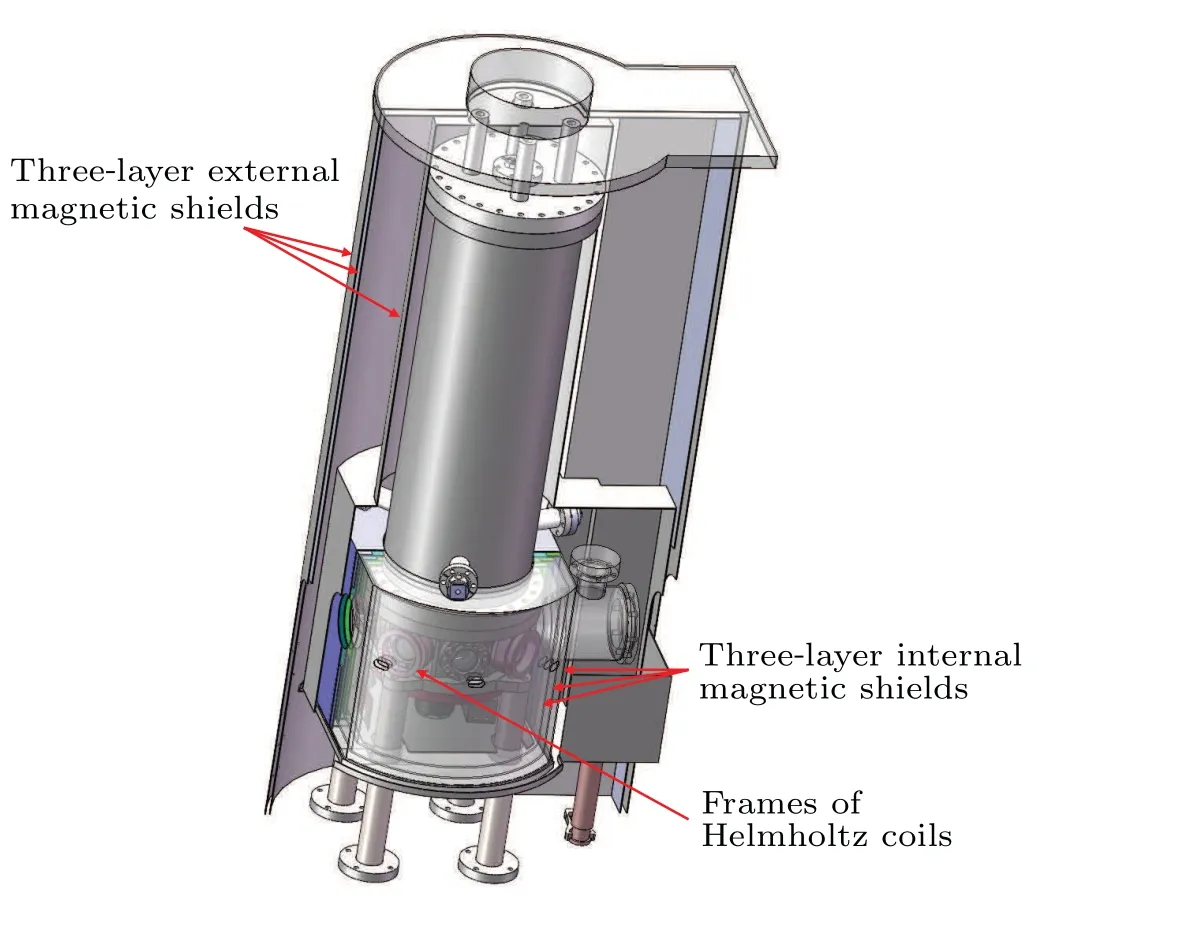
Fig.7.Schematic of the magnetic field shielding.The three-layer inner shields are mounted on the vacuum chamber.The three-layer outer shields are coaxial with the inner shields and are mounted on the nonmagnetic optical table.

Fig.8.The magnetic field fluctuations at the ion position obtained by the splitting of the clock transition between the Zeeman components.The results for cryogenic trap 1(black line)give a magnetic field jitter of 1.7 mHz in 14000 s.Cryogenic trap 2(red line)has a magnetic field jitter of 0.5 mHz over the same period of time.
Magnetic field noise is an important factor causing quantum decoherence in quantum systems, and in our previous work the clock transition linewidth was limited by the magnetic field fluctuations.To verify the improvement of the clock transition linewidth, a probe laser is used to synchronously probe both clocks.The blue line in Fig.9 shows the narrowest linewidth of the40Ca+ion2S1/2–2D5/2transition of cryogenic trap 1 of 18 Hz with an interrogation time of 40 ms.The yellow line in Fig.9 shows the result for cryogenic trap 2.By increasing the interrogation time to 150 ms, Zeeman transitions with a linewidth of 5.9 Hz were observed,which is three times smaller than the value for cryogenic trap 1.
6.Conclusion
In summary, we have presented a liquid-nitrogen cryogenic40Ca+optical clock.Compared with our previous work,many improvements have been introduced.The volume of the liquid-nitrogen container has been increased by a factor of three, so that the duration of liquid-nitrogen cooling has also been increased by almost three times.The fixation scheme for the liquid-nitrogen container has been optimized, reducing the recovery time of the ion trap position by almost three times.The number of layers in the magnetic shielding system has been increased, and an active magnetic field feedback scheme has been introduced, so that the magnetic field noise is also suppressed by more than three times.More highprecision temperature sensors are installed in the cryogenic system,with the aim of reducing the ambient temperature uncertainty of the ion.As a result of these efforts, the performance of liquid-nitrogen cryogenic optical clocks has reached or exceeded the level of room-temperature optical clocks in many aspects.With these improvements,an uncertainty evaluation for the40Ca+ion system below the 10-18level is expected to be within reach in the near future.
Acknowledgements
We thank Limit Vacuum Technology (Beijing) Co.Ltd for support of the vacuum system and for fruitful discussion and manufacturing.This work was supported by the National Key R&D Program of China (Grant Nos.2022YFB3904001 and 2018YFA0307500), the National Natural Science Foundation of China(Grant Nos.12121004 and 12022414),Strategic Priority Research Program of the Chinese Academy of Sciences (Grant No.XDB21030100), CAS Project for Young Scientists in Basic Research (Grant No.YSBR-055), CAS Youth Innovation Promotion Association (Grant Nos.Y201963 and Y2022099), the Natural Science Foundation of Hubei Province(Grant No.2022CFA013),and the Interdisciplinary Cultivation Project of the Innovation Academy for Precision Measurement of Science and Technology(Grant No.S21S2201).
猜你喜欢
杂志排行

Chinese Physics B的其它文章
- Optimal zero-crossing group selection method of the absolute gravimeter based on improved auto-regressive moving average model
- Deterministic remote preparation of multi-qubit equatorial states through dissipative channels
- Direct measurement of nonlocal quantum states without approximation
- Fast and perfect state transfer in superconducting circuit with tunable coupler
- A discrete Boltzmann model with symmetric velocity discretization for compressible flow
- Dynamic modelling and chaos control for a thin plate oscillator using Bubnov–Galerkin integral method