Dynamic modelling and chaos control for a thin plate oscillator using Bubnov–Galerkin integral method
2023-12-02XiaodongJiao焦晓东XinyuWang王新宇JinTao陶金HaoSun孙昊QinglinSun孙青林andZengqiangChen陈增强
Xiaodong Jiao(焦晓东), Xinyu Wang(王新宇), Jin Tao(陶金), Hao Sun(孙昊),†Qinglin Sun(孙青林),‡, and Zengqiang Chen(陈增强)
1College of Artificial Intelligence,Nankai University,Tianjin 300350,China
2Silo AI,Helsinki 00100,Finland
Keywords: thin plate oscillator, conservative chaos, Bubnov–Galerkin method, frequency response, chaos control
1.Introduction
The micro thin plate system, driven by acoustic waves,has found extensive applications in various engineering fields,such as microchip assembly,[1,2]cell culture,[3–5]and particle manipulations.[6–8]These tasks harness the advantages of acoustic manipulation based on vibration plates, which include: (i) miniaturization of control equipment, (ii) contactless manipulation,and(iii)compatibility with diverse manipulation targets and experimental environments.The underlying physical principle behind acoustic manipulation is the Chladni effect,discovered in 1787 by German physicist Ernst Florens Friedrich.[9,10]It is evident that the accuracy of manipulation in the thin plate system is closely influenced by the structure of the thin plate, as well as its material and geometric properties.Additionally,factors such as the driving signal source,amplitude, frequency, and driving interval play crucial roles in determining the effectiveness of micro thin plate manipulation.Hence,investigating the acoustic wave-driven micro thin plate vibration system holds both theoretical value and practical significance.
Simultaneously, there has been significant attention focused on nonlinear oscillators of various types,as they play a crucial role in engineering technology and industrial production.In recent years, several nonlinear oscillators with distinct characteristics have been investigated.For instance,Zhou and Chen reported on the Rayleigh–Duffing oscillator with non-smooth periodic perturbation and harmonic excitation.[11]Gendelmanet al.studied a forced vibro-impact oscillator with Coulomb friction.[12]Licsko and Csernak investigated the chaotic motions of a simple dry-friction oscillator.[13]Additionally,Liet al.demonstrated the nonlinear impact oscillators with bilateral rigid constraints.[14]Micro thin plate oscillators,with their promising and valuable prospects in various application scenarios,constitute an important branch of research.[15]The dynamic analysis of amplitude–frequency characteristics serves as a key indicator reflecting the performance of such oscillators.This analysis helps determine the resonance region and resonance frequency, which correspond to the maximum system energy under different parameter and geometric conditions.These findings serve as valuable guidance for adjusting and optimizing practical applications.
Furthermore, the discussion of chaotic dynamics in nonlinear vibration systems has gained attention in recent years due to its inevitability.Zhou and Chen investigated the chaotic motions of the Rayleigh–Duffing oscillator.[11]In Ref.[16],Meleshenkoet al.reported conservative chaos in a simple oscillatory system with non-smooth nonlinearity.Boudjema examined the dynamical manifestation of chaotic behavior in a q-Tsallis harmonic oscillator.[17]Alliluev and Makarov analyzed the dynamics of a nonlinear quantum oscillator under non-Markovian pumping.[18]Kruglovet al.revealed the features of a chaotic attractor in a quasiperiodically driven nonlinear oscillator.Alternatively,there are multiple methods to characterize the chaotic properties of a dynamic system.[19]The intuitive approach involves drawing phase portraits and sequence diagrams to observe the complexity and disorder of their evolution laws.Additionally,calculating the Lyapunov exponents(LEs) of a dynamic system can determine its chaotic nature.Positive LEs indicate a non-conservative system, while zerosum LEs suggest a conservative system.[20–25]Moreover,analyzing the dynamic evolution characteristics is another crucial aspect, which can be achieved through an improved method.In this paper, the thin plate oscillator is transformed into a three-dimensional (3D) autonomous system.The conservative chaotic characteristics of the proposed oscillator are revealed through theoretical analysis and simulation verification.The evolution process is illustrated by drawing dynamics maps based on various parameters and initial values, providing a comprehensive understanding of the system’s behavior.
In the field of chaos research,it is of great significance to model systems based on real-world backgrounds, as it helps guide practical engineering applications.However, there is a lack of research and analysis regarding the mechanisms of chaos.Fortunately,recent contributions from researchers have shed light on this aspect.One widely adopted approach is to progressively analyze the effects of force fields and energy within the system.For example,Pelinoet al.revealed the energy cycle of the Lorenz attractor,[26]while Yanget al.analyzed the mechanism of plasma chaotic systems by combining mechanics and energy principles.[27]Similarly,this paper explores the underlying reasons for the chaos observed in the modeled thin plate oscillator.Regarding the applications of chaotic systems, the randomness of chaotic sequences is typically considered.These applications encompass secure communication,image encryption,fault identification,signal prediction, and the stock financial fields.[28–30]Chaos refers to seemingly random and irregular motion within a deterministic system,exhibiting uncertain,unrepeated,and unpredictable behavior.Unfortunately,chaotic phenomena are not desirable in many engineering projects.Chaotic vibrations can lead to system instability, posing risks of damage, crashes, and reduced efficiency.Chaotic vibrations generate irregular oscillations,unpredictable interference fluctuations,increased mechanical load beyond bearing capacity, elevated noise levels,and diminished operational accuracy.Therefore, it is crucial to avoid chaotic phenomena in certain engineering applications.The goal is to effectively obtain the desired periodic orbit or suppress chaotic behavior through suitable strategies and methods.[31–34]Consequently, the effective suppression and control of chaos hold significant practical significance.In the proposed thin plate oscillator,chaos is controlled through the application of state feedback methods.
The rest of this paper is arranged as the following order:Section 2 presents the derivation of the governing equation for the thin plate oscillator through mechanical analysis and mathematical derivation.In Section 3, the amplitude–frequency response relationship is solved using the harmonic balance method(HBM),and the resulting amplitude–frequency curves are plotted to analyze the impact of various parameters and different vibration modes on the amplitude–frequency characteristics.Section 4 focuses on demonstrating the conservative chaotic behavior in the proposed oscillator through mathematical verification and numerical simulation.Additionally, the dynamics maps are computed to analyze the system’s evolution process and laws.The chaos mechanism is further explained by progressively analyzing the effects of force fields and energy.Importantly,the occurrence of chaos is controlled using the state feedback method.Finally, key findings and conclusions are presented in Section 5.
2.System governing equation
Revealing the complex dynamic behaviors of vibrating thin plate systems is of great practical value in engineering problems, particularly as a significant method of non-contact acoustic manipulation.[35]In this paper,the modeling analysis is based on a physical thin plate,as illustrated in Fig.1(a).A Silicon thin plate is securely attached to a Piezoelectric actuator and driven by a sinusoidal signal source,while a two-axis slider enables adjustment of the plate’s horizontal position.When subjected to different acoustic waves,the thin plate oscillator exhibits various types of vibrations,as depicted by the microparticles in Figs.1(b)–1(c), including both chaotic and regular vibrations.In this working system, chaotic vibration is undesirable and requires control,whereas regular motion is desirable.Therefore, it becomes necessary to control or suppress chaotic phenomena within this system.

Fig.1.The thin plate vibration system: (a) physical thin plate, (b) disordered vibration,and(c)regular vibration.
The forced vibration of a thin plate is characterized by small displacements, and the underlying rationale for these displacements lies in the complex stress conditions within the system.In addition, the geometry and material properties of the thin plate are key factors influencing its vibrational deflection.In this paper, we utilize the Kirchhoff–Love thin plate theory and take into account the stress conditions of the thin plate to derive the governing equation for the system,[36–38]as shown in Eq.(1)and the diagram is shown in Fig.2.

Fig.2.Diagram of simply supported thin plates on four edges.
It is important to note that the form of the external load,represented asp,and the reaction force,denoted asf,directly impact the dynamic characteristics of the vibrating thin plate system.
in which ∇4is the double Laplace operator, defined as ∇4=∇2(∇2w),Dis the bending rigidity of plate,ρis the plate density,his the plate thickness.p(x,y,t) is the external-driven mechanism,andA,ω,ϕare amplitude,frequency,and phase respectively of the driving signal.It is particularly worth mentioning,for a thin plate of elastic materials under the external excitation,the reaction force is considered asf=α|w|which is defined by analogy with Hooke’s law in this system,andαindicates the coupling strength of thin plate and driver.
The following boundary conditions should be met for a simply supported square thin plate.
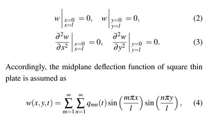
wheremandnare positive integers,lis the side length of square thin plate.
The residual function R for the forced vibration dynamic equation(1)is
Substituting Eq.(4)into Eq.(5),one gets
The energy function of a thin plate vibration system can be established by considering the kinetic energy and potential energy of the system.Kinetic energy of a thin plate can be expressed as the sum of the kinetic energy of each small mass element, and the potential energy of a thin plate can be expressed as the sum of the potential energies of various small elastic elements.The deflection function of thin plate vibrationw(x,y,t) has been obtained.Accordingly, the system kinetic energyTis expressed as
Consequently, the total energyEof the thin plate vibration system is expressed as the sum of kinetic energy and potential energyE=T+U.
The energy level distribution of a thin plate vibration system is influenced by its geometric shape, material properties,and boundary conditions.It can be characterized by the vibration modes exhibited by the system.Each vibration mode corresponds to a specific energy level,and the spacing between energy levels is determined by the vibration frequency.As a result,the energy level distribution curve of the proposed system is drawn as shown in Fig.3.
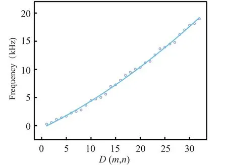
Fig.3.System energy level curve.
The horizontal axis in Fig.3 represents the vibration modeD(m,n), while the vertical axis is vibration frequency.The fitted energy level curve is close to a curve with an increase in slope, indicating that in the low vibration mode region, the frequency change is relatively small, while in the higher vibration mode, the frequency increase is relatively large.Based on previous research,[39]it can also be found that as the vibration modes increase, the vibration modes of the system become more complex.
3.Analysis of amplitude–frequency response
In this section,the amplitude-frequency response of system(9)is derived using the harmonic balance method,and extensive numerical simulations are conducted.Consequently,significant conclusions that closely affect the amplitude–frequency characteristics are obtained, which holds vital significance for the vibration control of square thin plate systems.The forced vibration state represents the system’s response to continuous and uninterrupted excitation forces.When the excitation source is removed, the vibration transitions into free vibration based on the natural frequency of the system.The system’s response under simple harmonic excitation consists of transient response and steady-state response.During the steady-state response, the vibration frequency of the system matches that of the excitation force.When the frequency of the excitation force approaches the natural frequency of the system,the vibration amplitude undergoes a sudden increase,leading to resonance.While resonance can be detrimental in certain scenarios,it can also be skillfully harnessed for beneficial purposes.Hence,understanding the amplitude–frequency characteristics is a crucial research aspect for oscillators.
3.1.Amplitude–frequency response
Relabel the coefficients of Eq.(9) for simplifying, one gets

Then, substituting Eqs.(13) and (14) in the dynamic system Eq.(12), and considering the positive cos(ωt+ϕ), the following equations is derived:
Squaring both sides of Eq.(15) and adding them separately,consequently,one gets

3.2.Amplitude–frequency curves
To investigate the impact of system parameters on the amplitude–frequency response, numerical simulations were conducted to elucidate the evolution patterns of the proposed oscillator’s amplitude–frequency response.This study primarily focuses on examining the effects of various parameters,including the sheet thicknessh, sheet side lengthl, amplitude of external excitation forceAand vibration modes(m,n).For all simulation conditions, the material parameters are set according to Silicon,which has a density 2329 g/m3,a Young’s modulus of 170×109Pa, and a Poisson’s ratio of 0.28, andµ=0.2,α=1.
Case 1 Analysis of the sheet thicknessh
In this case,the amplitude–frequency response curves are computed with different sheet thicknesshand under the vibration modes(m=1,n=1),(m=1,n=3).Other parameters are selected as,sheet side lengthl=0.1 m,excitation amplitudeA=100.
From the amplitude–frequency response curves with distinct color shown in Figs.4(a) and 4(b), in which, the plate thickness are selected ash= 0.2 mm,h= 0.4 mm, andh=0.6 mm respectively for different vibration modes(m=1,n=1)and(m=1,n=3).From Figs.4(a)and 4(b),the conclusion is that with the increase of plate thickness,the amplitude of thin plate decreases,inversely,the resonance frequency is increasing.The vibration mode changes from(m=1,n=1)to(m=1,n=3),but the amplitude decreases.For engineering application,it suggested that the thinner plates and higher order vibration modes are considered to avoid large resonance amplitude causing damage to the sheet system.Case 2 Analysis of the side lengthl

Fig.4.Amplitude frequency characteristics under different vibration modes(m, n) and plate thickness (h): (a) vibration mode (m=1, n=1) and (b)m=1,n=3.
In Case 2,based on the equation of amplitude–frequency response, the effect of the sheet side lengthlis simulated.The side lengthlof the square thin plate are set asl=5 cm,l=10 cm,andl=15 cm for vibration modes(m=1,n=1)and(m=1,n=3)separately.The plate thickness is fixed as 0.2 mm,excitation amplitudeA=100.And the corresponding amplitude–frequency response curves are shown in Figs.5(a)and 5(b),with the increase of the side length of the thin plate,the amplitude of the thin plate also increases.Instead,the resonance frequency becomes smaller,concurrently,the resonance amplitude is increasing.In addition,the resonance frequency will enlarge with the increase of vibration mode evidently.

Fig.5.Amplitude frequency characteristics under different vibration modes(m,n)and side length(l):(a)vibration mode(m=1,n=1)and(b)vibration mode(m=1,n=3).
Case 3 Analysis of the excitation amplitudeA
The influence of the excitation amplitudeAis analyzed in this case.The sheet thickness and the sheet side length,separately,are chosen ash=0.4 mm,l=0.1 m.Amplitude–frequency response curves are shown in Figs.6(a)and 6(b)for the vibration modes(m=1,n=1),(m=1,n=3).
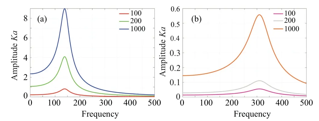
Fig.6.Amplitude frequency characteristics under different vibration modes(m,n)and side length(A): (a)vibration mode(m=1,n=1)and vibration mode(m=1,n=3).
According to the simulation results, the excitation amplitudeAwill not transform the resonance frequency but the vibration amplitude increases.Other parameter settings remain unchanged, the resonance frequency increases with the increase of vibration mode.Hence, excitation amplitudeAis an crucial factor to adjust the vibration amplitude of thin plate,which are important application index in vibration system.
Through the analysis of the amplitude–frequency response under various vibration conditions and modes, valuable practical conclusions can be drawn, which can further guide the application of vibration systems.These findings are closely related to the selection of vibrating thin plate properties and the adjustment of excitation forces in engineering applications.Based on the three types of simulations mentioned above, while keeping other conditions constant, it can be observed that increasing the vibration mode results in a reduction of the vibration amplitude in the thin plate vibration system.Consequently, with reference to the results obtained from the analysis, the potential damage to the vibration system can be avoided,thereby enhancing the overall application efficiency of the vibration system.
4.Chaotic property and its control
Chaos phenomena are commonly observed in various nonlinear systems, and they are an inherent characteristic of vibration systems.However, conservative chaos, which is a specific type of chaos, has received limited attention in research.Chaotic behavior in dynamic systems manifests as strong randomness.While chaotic systems have advantages and applications in certain industrial production fields, such as chemical reactions and meteorological predictions,as well as secure communication,chaos should be avoided in the case of thin plate oscillators to ensure system stability and safety.Methods for controlling chaos can generally be categorized as feedback control and non-feedback control.In this study, the chaotic phenomenon in the proposed thin plate oscillator is thoroughly analyzed through theoretical analysis and numerical simulations,and subsequently controlled using state feedback methods.
4.1.Conservative chaos and dynamic evolution
Conservative chaos can be determined by Lyapunov exponents and the phase space trajectory of the system.In Eq.(9),the relationship between the vibration response of the thin plate and the parameters is described.Simplify the system parameters and relabel the variables, one gets the state equation form of system(9)as
in which,xindicates the generalized displacement, andymeans the generalized velocity,and the simplified parameters can still reflect the impact of changes in the original parameters on the system.Setz=ωt, a 3D autonomous dynamic system(19)can be obtained
the corresponding Jacobian matrix is
When the initial valuesx0,y0,z0are set as(0.2,100,0.05),the parameters are set asa=2,b=300,c=0.001,n=1.5,andd=2.1.The proposed dynamic system(19)presents chaotic characteristic because the Lyapunov exponents is calculated as+0.0512, 0.0000,-0.0522 shown in Fig.7(a).Using the results of Lyapunov exponents of the 3D autonomous dynamic system(19),the Lyapunov dimension can be obtained by
as a result,DL=2.98≈3,the calculation results tend to integer,which also shows the conservative chaotic characteristics of the system.
Simultaneously,the divergence of system(19)can be calculated according to
consequently, the degree of dissipation for system(19)is determined by the value of parameterc,in this proposed chaotic state,c=0.001, which is close to 0, that means the volume of phase space of system(19)is constant, and the spatial trajectories are neither divergent nor convergent.Combined with the calculation results of Lyapunov exponents(+,0,-), Lyapunov dimension (tend to integer, 2.98≈3), divergence (approximate to 0), the chaotic phenomenon with all these characteristics can be classified as the conservative chaos.And the corresponding chaotic attractor is displayed in Fig.7(b),which is formed by complex spatial trajectories and shows the chaotic property of the proposed thin plate oscillator.
In addition, the evolution process of dynamic system directly reflects the characteristics of the system.For the purpose of investigating the dynamic evolution process, the dynamics maps of system(19)is drawn with various parameter and initial condition.As system(19)is a 3D dynamic system,meanwhile,there is always 0 LE during the calculation process to keep the stability of the system.Thus,the first LE is a key indicator reflecting the dynamic evolution process.In which,the positive first LE indicates the chaotic motion,inversely,the negative or zero first LE represents the regular motion of the system.

Fig.7.The chaotic property of system(19): (a)Lyapunov exponent spectrum and(b)the chaotic attractor in x–y plane.
The dynamics maps for system (19) are presented in Figs.8(a)and 8(b),illustrating the influence of variable parameters and initial values on the system’s behavior.In Fig.8(a),the parameter rangea ⊂[0,10] and initial value rangex0⊂[5,15]are divided into increments of 0.1.The yellow surface region in Fig.8(a)represents chaotic states with a positive first Lyapunov exponent(LE),while other regions indicate regular motion with a negative first LE.It is noteworthy that the system’s evolution process remains unaffected by changes inx0,but varies with the parametera.Figure 8(b)demonstrates the dynamic evolution with varyingbandz0, displaying the calculated results of the first LEs.Notably, the dynamic evolution process exhibits symmetry about the parameter axisb=0.Additionally,the system evolves with different degrees of randomness across various regions,as indicated by the color bar in Fig.8(b).Regions marked in red exhibit higher randomness, while those marked in blue exhibit lower randomness.The method of drawing dynamics maps provides a valuable tool for intuitively analyzing the system’s evolution patterns based on parameters and initial conditions.
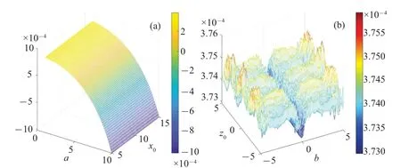
Fig.8.The dynamics map of system(19)with varying parameters and initial values: (a) the dynamics map with varying a and x0, (b) the ynamics map with varying b and z0.
Moreover,an intricate and intimate correlation exists between the dynamic behavior of the thin plate vibration system and the amplitude frequency characteristics it exhibits.The system’s chaotic and stable states exert a discernible influence on its amplitude frequency characteristics, which can be unveiled by comparing the simulation results.
4.2.Analysis of chaos mechanism
Chaotic or hyperchaotic systems can be effectively represented by a generalized Hamiltonian system,which can further be described in the Kolmogorov form.This representation allows for the decomposition of the dynamic system into three distinct force fields: the conservative force field, dissipative force field, and external force field.By analyzing the effects of these force fields on the system and observing the variations in system energy,we can explain the mechanism behind the emergence of chaos.In the case of system(19), it can be expressed as follows:
Go a step further
in which{x,H}is the conservative force field, the dissipative force field is indicated byfd,femeans the external force field.As consequence,the chaotic mechanism of the proposed thin plate oscillator can be analyzed gradually.The system parameters and initial conditions are also set as those in Subsection 4.1.
Firstly,when only the conservative forcex,Hacts on the system,energy conservation is maintained,and there is no exchange of energy between the system and its surroundings.As a result, the system exhibits stable evolution.This is supported by the numerical simulations presented in Figs.9(a)and 9(b),where the corresponding phase space portrait forms a closed periodic ring,and the system’s state variables change uniformly.Next,the dissipative force is introduced,which disrupts the system’s conservative behavior.The spatial trajectory of the system then becomes quasi-periodic,as depicted in Fig.10(a),deviating from simple periodic motion.Over an extended period of time,the system gradually dissipates,as illustrated by the time history curve shown in Fig.10(b).Finally,the external forcefeis added, incorporating the influence of all force fields on the system.Notably,due to the presence of the external forcefe,energy exchange occurs between the system and its surroundings.Consequently,chaos emerges in the system,driven by the fluctuations in system energy.This is depicted by the chaotic attractor in 3D space shown in Fig.11(a),and the disorderly behavior observed in the time history curve of variablexpresented in Fig.11(b).The interplay between the force fields and system energy provides valuable insights into the occurrence of chaos in the thin plate oscillator.
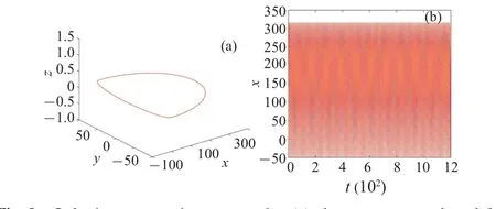
Fig.9.Only the conservative term works: (a)phase space portrait and(b)the time history curve of x.
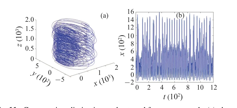
Fig.11.Conservative,dissipative,and external force terms work: (a)phase space portrait and(b)the time history curve of x.
4.3.Chaos control based on state feedback
The dynamic motion resulting from chaos is characterized by violent oscillation.Unfortunately, the presence of chaos leads to an unstable state,which is detrimental in practical engineering projects.Engineers strive for system stability in a steady-state, aiming to avoid any bifurcation or chaotic behavior.Chaos control involves guiding a controlled chaotic system away from its chaotic state and achieving the desired periodic dynamic behavior,such as an equilibrium state,periodic motion,or quasi-periodic motion.The primary objective of chaos control is to eliminate bifurcation and chaos in the system.Therefore, the rapid suppression of chaos becomes a critical control task in engineering.Chaos control primarily aims to eliminate chaos and prevent its occurrence,ultimately stabilizing the system at the desired equilibrium point or periodic state.
In Subsection 4.1,the conservative chaotic property of the proposed thin plate oscillator,a class of chaos with higher randomness,is analyzed in detail.The method of state feedback is used to suppress the chaos in this subsection.For system(19),the displacement feedback controlleru1and velocity feedback controlleru2are designed to control the chaos appeared in last subsection.Under the action of the controllers,the governing equation of the system becomes
in which the controllers are set asu1=-k1x,u2=-k2y.Set the system parameters according to Subsection 4.1,letu2=0,and the displacement state feedbacku1is set asu1=-2x.The governing equation of system becomes
The spatial trajectory and time series of variablexare obtained through simulations, as shown in the Figs.12(a) and 12(b).From the simulation results,the spatial trajectory inx–yplane shown in Fig.12(a)is a purple closed curve illustrating that the control result is periodic state, and the time series are changing regularly and evenly as the light blue sequence diagram shown in Fig.12(b), which show that the chaotic behavior of the system is effectively eliminated under the action of the displacement feedback controlleru1.
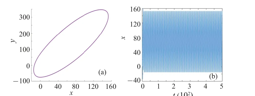
Fig.12.Control results of the displacement feedback controller u1: (a)phase portrait in x–y plane and(b)the time history curve of x.
And next,letu1=0,and the velocity state feedbacku2is set asu2=-3y.The governing equation of system becomes
Accordingly,the phase portrait and time series of variablexare shown in the Figs.13(a)and 13(b).From the simulation results above, the phase portrait and the time series explain the periodic state of system (27), which also verify the effectiveness of the designed velocity feedback controlleru2for controlling the chaotic behavior of the proposed thin plate oscillator.
Applying an external controller introduces potential control costs.Firstly,incorporating state feedback into the system may increase the control response time.Additionally, the effectiveness of control depends on the selection of controller parameters, presenting a crucial challenge for achieving system robustness.Furthermore, in mechanical control systems,the use of external controllers entails energy consumption and maintenance costs.Designing a state feedback controller for chaos control is to achieve the desired dynamic behavior in a chaotic system, enabling the system to transition from an disordered chaotic state to a stable periodic motion or other desired state.In engineering applications, chaos control has important application value in anti-interference, stability enhancement,communication encryption,oscillator design,and system modeling analysis.
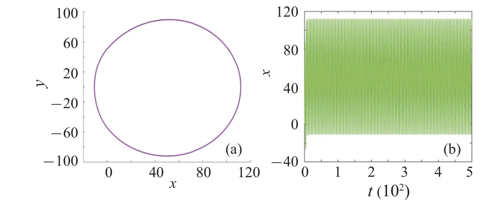
Fig.13.Control results of the velocity feedback controller u2: (a) phase portrait in x–y plane and(b)the time history curve of x.
5.Conclusion
The application of a thin plate system driven by acoustic waves holds significant promise in various fields,including micro-nano manipulation, tissue culture, and self-assembly.This paper presents a comprehensive analysis of a micro thin plate vibration system driven by acoustic waves.Firstly, the governing equation of the system is derived by considering the mechanical conditions of the thin plate microelement and conducting detailed mathematical analysis.The energy function and energy level distribution of the system are also discussed.Secondly, the amplitude–frequency response function of the thin plate oscillator is solved, and corresponding amplitude–frequency curves are plotted.The influences of three system parameters and two vibration modes on the amplitude–frequency characteristics are summarized,providing valuable insights for practical applications.Furthermore, the occurrence of conservative chaotic motions in the thin plate oscillator is revealed through mathematical calculations and numerical simulations.The evolution process of the system is explored by constructing dynamics maps,illustrating the system’s behavior.Additionally, the emergence of chaos is explained by analyzing the effects of force fields and system energy.Finally, displacement and velocity state feedback controllers are designed to control the chaos, resulting in the attainment of a periodic state and preventing unexpected damages in engineering applications.These findings contribute to advancing the understanding and utilization of thin plate vibration systems driven by acoustic waves,opening up new avenues for their practical implementation.
Acknowledgements
Project supported by the National Natural Science Foundation of China (Grant Nos.61973172, 62003177,62103204, 62003175, and 61973175), the Joint Fund of the Ministry of Education for Equipment Pre-research (Grant No.8091B022133),and General Terminal IC Interdisciplinary Science Center of Nankai University.
杂志排行

Chinese Physics B的其它文章
- Optimal zero-crossing group selection method of the absolute gravimeter based on improved auto-regressive moving average model
- Deterministic remote preparation of multi-qubit equatorial states through dissipative channels
- Direct measurement of nonlocal quantum states without approximation
- Fast and perfect state transfer in superconducting circuit with tunable coupler
- A discrete Boltzmann model with symmetric velocity discretization for compressible flow
- Analysis of anomalous transport with temporal fractional transport equations in a bounded domain