Emergence of correlations in twisted monolayer–trilayer graphene heterostructures
2023-10-11ZhangZhou周璋KenjiWatanabeTakashiTaniguchiXiaoLin林晓JinhaiMao毛金海andHongJunGao高鸿钧
Zhang Zhou(周璋), Kenji Watanabe, Takashi Taniguchi,Xiao Lin(林晓), Jinhai Mao(毛金海),‡, and Hong-Jun Gao(高鸿钧)
1School of Physical Sciences and CAS Center for Excellence in Topological Quantum Computation,University of Chinese Academy of Sciences,Beijing 100049,China
2Advanced Materials Laboratory,National Institute for Materials Science,Tsukuba,305-0044,Japan
3Institute of Physics,Chinese Academy of Sciences,Beijing 100190,China
Keywords: twisted multilayer graphene,correlated states,electric tuning
1.Introduction
Graphene-based moiré systems are emerging as a platform for creating novel quantum states, where the moiré Bloch bands form by tuning the weakly coupled Dirac electron with a periodic moiré potential.[1,2]The twisted bilayer graphene(tBG),as the simplest structure, demonstrates the effective formation of flat bands in both theory[3–5]and experiments.[6–10]Intuitively, the concept will also apply to twisted multilayer graphene.Specifically, twisted (M+N)-layer graphene is predicted to host two low-energy flat bands for each valley emerging from the interface between theMandNlayers.[11–13]The extended structures successfully exhibit novel quantum phases,such as spin-polarized insulating states in twisted double-bilayer graphene (tDBG)[14–16]and quantum anomalous Hall effects in twisted monolayer–bilayer graphene(tMBG).[17]
Moving one step forward would involve stacking monolayer and trilayer graphene (TLG) together with just a single twist angle,which has been theoretically proposed to host correlated and topological states.[11,18]Notably, two stacking orders naturally exist in TLG, Bernal (ABA) stacking with mirror symmetry and rhombohedral (ABC) stacking with inversion symmetry,[19,20]where alternative degrees of freedom are appreciated.When considering the structure of twisted monolayer–trilayer graphene(tMTG),the inversion symmetry is naturally absent,leading to the anticipation of electron–hole asymmetry and asymmetry with the direction of the displacement field at low-energy bands.Experimentally constructing the tMTG heterostructure would be rewarding to extend the family of graphene superlattices and to examine the evolution of correlation effects.
In this work,we investigate the electrical transport properties in tMTG (Bernal-stacking trilayer) dual-gated devices with twist angles of 1.45°and 1.51°, and report clear observations of correlated phases.We find that the resistance peak at full fillings (ν=±4) and ‘halo’ regions are highly dependent on the charge density and displacement field.Correlated phases at commensurate fillings(ν=1,2)of a moiré unit cell are revealed at a high displacement field (D <-0.3 V/nm)and stabilized with a specific magnetic field (>0.04φ0,φ0represents the quantum flux of the moiré unit cell) on the electron-doping side.The lifting of degeneracy is observed from the Landau fan diagram at the integer fillings.Our results have broadened the scope and enriched the family of twisted graphene moiré superlattices.
2.Twisted monolayer–trilayer graphene
The tMTG stacks in this work were fabricated by picking up the flakes sequentially following the van der Waals drytransfer method.[21]See the fabrication details in the supporting information.The MLG and TLG were both obtained from one single flake to realize more precise control of the twist angle.Then, the assembled stacks were released onto a prepatterned SiO2/Si substrate and fabricated into multi-terminal Hall devices for transport measurements.A schematic of the whole device is shown in Fig.1(a).An optical image of a typical device is shown in Figs.1(b) and S1(a).The schematic moiré pattern is shown in Fig.1(c),where the period isλ=a/2sin(θ/2) with a relative twist angleθand lattice constant of graphenea=2.46 ˚A.In the ABA trilayer stacking,the top and bottom layers are overlapped from the top or bottom view;therefore,the schematic moiré pattern from the top view is the same as the tMBG.Gate tuning is independently applied through the metallic top gate and silicon bottom gate to tune the carrier density and displacement field continuously.The total charge doping density isn=(CbgVbg+CtgVtg)/eand the displacement field is|D|=CbgVbg-CtgVtg/(2ε0),whereε0is the vacuum permittivity,VbgandVtgare the effective gate voltages,andCbgandCtgare the capacitance per unit area of the bottom and top gate,respectively.The filling factor isν=4n/nswherensis the full-filling carrier density of the moiré unit cell.

Fig.1.Twisted monolayer–trilayer graphene.(a) A schematic of the tMTG device structure.The top gate is the gold electrode,and the bottom gate is Si/SiO2.(b) An optical microscope image of the tMTG device.The scale bar is 10 μm.(c) An illustration of the moiré pattern of stacked tMBG graphene with the relative twist angle θ.Here,λ is the period of the moiré pattern.(d) The longitudinal resistance measured when scanning the top gate voltage(Vtg)with the bottom gate grounded.As the device is cooled down from 150 K to 2 K,two resistance peaks emerge at full filling of the moiré unit cell.
Transport measurements are conducted in a physical property measurement system (PPMS) in the four-terminal setup.As the device is cooled down,the common feature is the resistance peak emerging at the full filling state of the moiré unit cell,as shown in Fig.1(d).When only scanningVtgwithVbgset to 0,the onset temperature of resistance peaks as high as 150 K is observed,and the resistance peaks soon grow as the temperature decreases.This is a hallmark of twisted graphene moiré superlattices and indicates the single-particle energy gap between reconstructed flat bands and remote bands.The sheet resistance of the insulating state at 2 K is as high as~200 kΩ at the insulating full filling state and drops sharply to as low as~0.1 kΩ,with the difference greater than three orders of magnitude.The peaks of the three channels at full fillings coincide with each other in Fig.S2, indicating a uniform twist angle differing by less than±0.01°in the channel length of~5 μm.The relative twisted angles are extracted from the carrier density at full fillings and further confirmed by the value of the quantum magnetic fluxφ0more precisely.
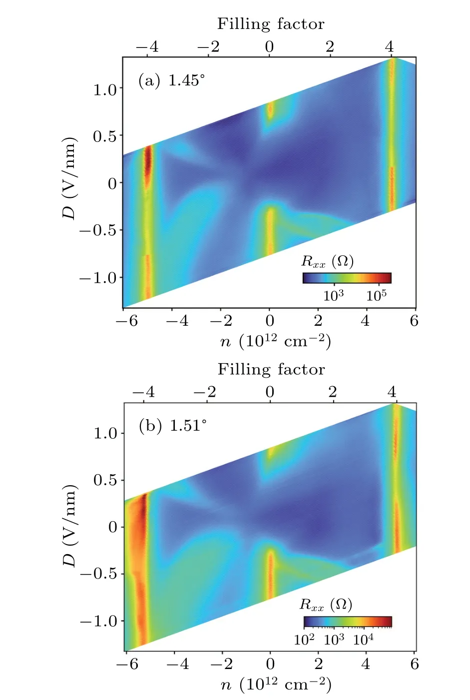
Fig.2.The emergence of correlation in the tMTG devices.Mapping of the longitudinal resistance of the tMTG device on the carrier density n(filling factor) and displacement field D with twist angles of 1.45° (a) and 1.51°(b),measured at a temperature of 2.0 K and a magnetic field of 0 T.
The top and bottom gate voltages are then simultaneously scanned to obtain a detailed map of the longitudinal resistance,which is normalized to relations withνandD,with the twisted angle of 1.45°in Fig.2(a) and 1.51°in Fig.2(b).The positive direction ofDis defined when the electric fields point from TLG to MLG,for consistency when comparing different tMTG devices, considering the breaking of the mirror reflection symmetry.Resistance peaks emerge at full fillings at both the electron-doping and hole-doping sides.In the measured range ofDat the full fillings, the resistance is minimum at a relatively lowDand increases at both ends.On the hole side,‘cross-shaped’resistivity peaks emerge in the whole measured range ofD,and the filling factor of the resistivity peak evolves withDconnecting the charge neutral point(CNP)and full fillings.On the electron side, high contrast ‘halo’ regions only emerge in the negativeDrange,where the electron density is polarized and distributed mainly at the twisted interface.[22,23]
3.Tunable band structure
Next,we move on to revealing the correlated phase in detail on the device ofθ=1.45°.As the temperature is cooled from 15 K to 2 K, the resistance peaks start to emerge near the integer fillingsν=1,2,and 3 and nearν=-3 in theRxxcurve as a function ofνat a relatively largeD=-0.5 V/nm,as shown in Fig.3(a).These peaks could not be explained in the single-particle picture and indicate the onset of correlations.The relatively low resistance (~1 kΩ) and metallic behavior atD <0 suggest that the correlation effects only cause partial gap opening or band overlaps, rather than the opening of bandgaps.
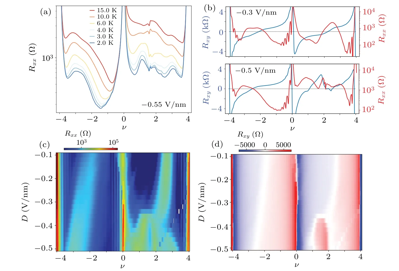
Fig.3.Tunable band structure and transport properties of the tMTG device with θ =1.45°.(a) Rxx as a function of the filling factor at D=-0.55 V/nm at a series of temperatures from 15 K to 2 K at B=0.(b) Rxx (red) and Rxy (blue) as a function of the filling factor at D=-0.3 V/nm(top panel)and-0.5 V/nm(bottom panel)and B=2.0 T.The horizontal dashed lines indicate Rxy=0.(c),(d)Mapping of Rxx (c)and Rxy (d)on the filling factor and displacement field at an external magnetic field B=2.0 T and temperature T =2.0 K.
A magnetic field of 2 T(<0.05φ0)is then applied to identify whether the band curvature is electron-like or hole-like,which is estimated based on the states whereRxychanges sign,as shown in Fig.3(b).These kinds of changes in the band curvature are typically related to van Hove singularities (vHSs).The vHSs appear on both the electron and hole sides and span the wholeDrange from-0.1 V/nm to-0.5 V/nm,as depicted in Fig.3(d).For ease of comparison,Fig.3(b)depicts two panels exhibiting theRxx(red)andRxy(blue)as a function of the filling factor atD=-0.3 V/nm and-0.5 V/nm,respectively.As demonstrated in Fig.3(b),Rxxpeaks emerge at the positions of vHSs, and the sign ofRxychanges correspondingly.Moreover, the positions of vHSs evolve withD.The white stripes(vHSs,Rxy=0)on both the electron and hole sides of Fig.3(d) show the same trend as the position of the peaks in Fig.3(c).The change inRxy’s sign is commonly related to saddle points in the momentum space,which is comparable to the tBG and tMBG devices.[24,25]
Despite applying a relatively weak magnetic field, the correlated phases are considerably strengthened, as depicted by the comparison between Figs.3(c)and S3(a).As observed on the electron-doping side, the central position of the highcontrast stripe evolves fromν=3 to 2 whenDincreases from-0.1 V/nm to-0.35 V/nm.AboveD=-0.35 V/nm,the single peak sharply splits into two peaks, which appear around commensurate fillings ofν=1 and 2 and remain unchanged withD.The corresponding changes are also observed in theRxymapping, as shown in Fig.3(d).Notably, the magnetoresistance(Shubnikov–de Haas, SdH)oscillations are observed around resistance peaks close to the CNP and full fillings in both panels of Fig.3(b).Furthermore, additional oscillations nearν=2 are found atD=-0.5 V/nm in the bottom panel,which suggests new band edge formation due to enhanced electron correlations at the half-filling.
It is therefore intriguing to systematically reveal the detailed magneto oscillation evolution with the magnetic field,which could provide insights into the Fermi surface and degeneracy associated with electronic degrees of freedom.A perpendicular magnetic field (B) will have impacts on graphene moiré superlattices in two different ways.First,the magnetic field would induce splitting between the flat bands with opposite Chern numbers due to the orbital Zeeman effect, which assists to isolate and stabilize the flat bands.Second,the magnetic field tends to recombine the flat bands into a sequence of fractal Landau levels(LLs),also known as Hofstadter’s butterfly spectra,[26]in which the recurring fractal bands are dependent on the number of magnetic fluxes in each moiré primitive cell.The Landau fan diagram for the tMTG device of 1.45°atD=-0.5 V/nm andT=2.0 K is presented in Fig.4(a).In the hole-doping region, the Landau fan exhibits a complex Hofstadter’s butterfly pattern.The pattern reveals the crossing of Landau levels from the CNP and the full filling of holes,as a result of commensurate flux threading into the unit cell.Fractional flilings ofφ0,φ0,φ0andφ0could be identifeid and are emphasized with horizontal dashed lines.
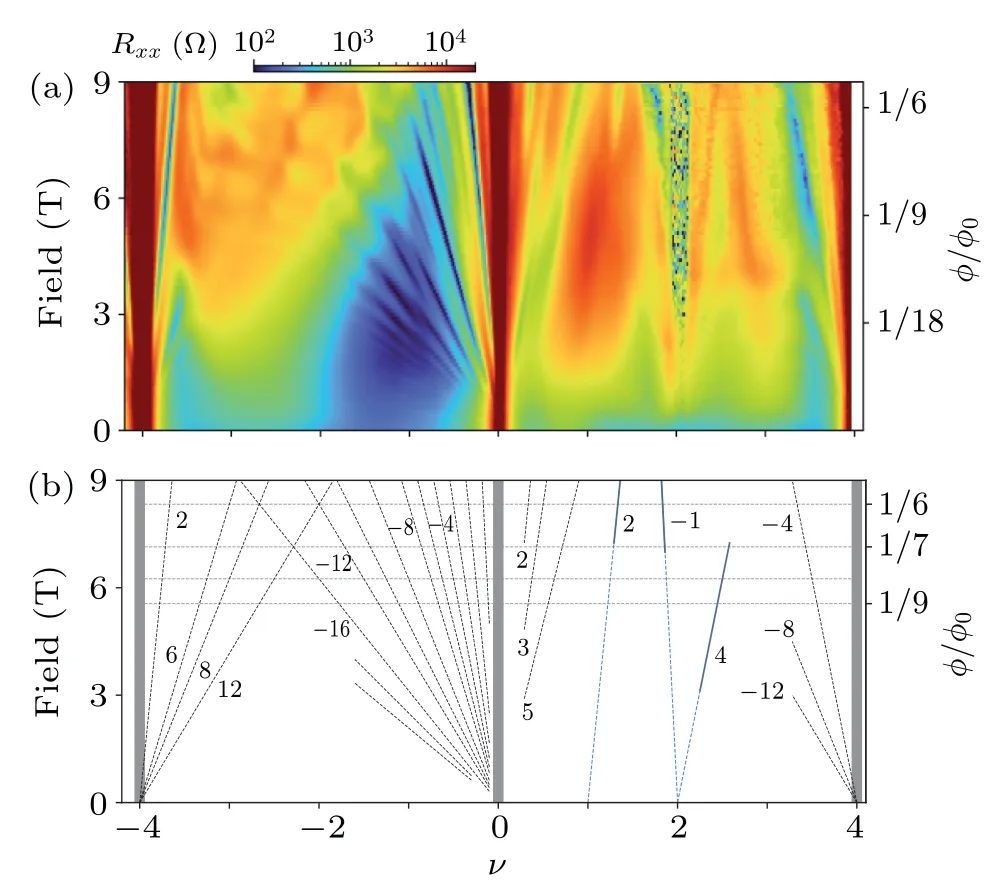
Fig.4.Quantum oscillations in the tMTG device with θ =1.45° at D=-0.5 V/nm and T =2.0 K.(a) The Landau fan diagram on the tMTG device.Numbers at the right y-axis indicate φ/φ0 fractions,where φ0 =h/e,h is the Planck constant,e is the electron charge,and φ =BS is magnetic flux through a moiré unit cell.The Landau-level structure extracted from the oscillations is plotted in (b).The tilted dashed lines correspond to the Landau levels,with sequences labelled.The blue lines originate from the filling factors υ =1 and 2.The black lines originate from the charge neutrality point(CNP),and full fillings of the moiré unit cell at both the electron and hole sides.The horizontal dashed lines indicate fractal values 1/6,1/7,1/8 and 1/9 of φ/φ0.
We observe linearly dispersing features on the electron side emanating from integer fillings.The linearly dispersing features can be characterized by fitting the Diophantine equation(Fig.4(b)),ν=Cφ/φ0+ν0,whereφis the magnetic flux per moiré unit cell,φ0=h/eis the flux quantum,his Planck’s constant,eis the elementary charge of an electron, andν0is the band filling index or the number of carriers per unit cell atB=0 T.Trajectories emanating from the CNP,ν0=0,despite being unaffected by the moiré potential, still form a bilateral Landau fan.Specifically,the LLs ofC=-1,-2,-3,-4,-5,-6,-8,-10,-12,-16,...on the hole-doping side mainly contribute to the fan.Meanwhile,on the electron-doping side,only LLs ofC=2, 3, 5 could be distinguished, displaying a fully lifted degeneracy.At the full filling of holes(ν0=-4),the LLs ofC=2,6,8,and 12 are observed at symmetry broken to two-fold degeneracy,while at the full filling of electrons(ν0=4),the LLs ofC=-4,-8,and-12 are observed,indicating four-fold degeneracy.
Notably, the correlated phase is enhanced with the increase in the magnetic field.The feature(C=2)fanning fromν0=1 starts emerging from the feild ofat the electron branch.For the two linear features fanning fromν0=2, theC=-1 feature starts emerging at aroundat the hole side,and theC=4 feature emerges at a relatively low field.No additional features have been found to decipher the remaining degeneracy.This is consistent with previous studies of tBG and tMBG, in which STM/STS measurements have indicated that a Dirac-like dispersion is revived at each quarter band filling due to a cascade of spontaneously broken symmetries.[28,29]
In summary, we report the observation of a correlated phase in a tMTG structure with twist angles of 1.45°and 1.51°.The correlated phase of the tMTG structure exhibits similarities to tMBG regarding the broken mirror symmetry and electron-hole asymmetry.These correlated phases are revealed only under a relatively large displacement field and are stabilized under a moderate magnetic field.Our findings have expanded the parameter space of the twisted graphene family, and may stimulate further research on twisted multilayer graphene.
Acknowledgements
We acknowledge support from the National Key R&D Program of China (Grant No.2019YFA0307800, J.M.), Beijing Natural Science Foundation (Grant No.Z190011, J.M.),the National Natural Science Foundation of China (Grant Nos.11974347, J.M.and 12204479, Z.Z.), and Fundamental Research Funds for the Central Universities(J.M.).
猜你喜欢
杂志排行

Chinese Physics B的其它文章
- Dynamic responses of an energy harvesting system based on piezoelectric and electromagnetic mechanisms under colored noise
- Intervention against information diffusion in static and temporal coupling networks
- Turing pattern selection for a plant–wrack model with cross-diffusion
- Quantum correlation enhanced bound of the information exclusion principle
- Floquet dynamical quantum phase transitions in transverse XY spin chains under periodic kickings
- Generalized uncertainty principle from long-range kernel effects:The case of the Hawking black hole temperature