A mathematical analysis: From memristor to fracmemristor
2022-06-29WuYangZhu朱伍洋YiFeiPu蒲亦非BoLiu刘博BoYu余波andJiLiuZhou周激流
Wu-Yang Zhu(朱伍洋) Yi-Fei Pu(蒲亦非) Bo Liu(刘博) Bo Yu(余波) and Ji-Liu Zhou(周激流)
1College of Computer Science,Sichuan University,Chengdu 610065,China
2College of Physics and Engineering,Chengdu Normal University,Chengdu 611130,China
3Chengdu University of Information Technology,Chengdu 610225,China
Keywords: fractional calculus,fractional-order memristor,fracmemristor,memristor
1. Introduction
In 1971, Leon O. Chua predicted the existence of memristor[1,2]theoretically according to the combinatorial completeness principle of basic circuit variables, and called memristor the fourth basic circuit element lost by human beings. However, no actual physical element was found at that time. In 2008,[3]the team led by the American scientist R.Stanley Williams produced a TiO2device at the nanoscale,which was proved by analysis to be a memristor physical entity, shocking the international electrical and electronic field. Worldwide research on memristor has been initiated.Chua[2,4,5]argued for a broader definition that included all 2-terminal non-volatile memory devices based on resistance switching.Recently,memristor systems have been extended to memory capacitor(memcapacitor)and memory inductor(meminductor). Memristor can perform both storage and computation functions at the same time,becoming a key component of future non-Von Neumann computing systems that integrate information storage and computation. In computer science,neural network,[6]biological engineering,[7]communication engineering and nonlinear circuits[1,8]and other fields, it has a wide range of application prospects,and attracts people’s attention and research.
For nearly 300 years, fractional calculus has become an important branch of mathematical analysis. How to apply fractional calculus to modern signal analysis and processing is a new branch of science which is seldom studied in the world at present. The fractional calculus is a kind of calculus whose operation order is non-integer, which has longterm memory, non-locality and weak singularity.[9,10]Moreover, the fractional parameters can increase the extra degree of freedom of the system. Because of these advantages of fractional order calculus, many systems combine fractional order calculus circuit and system, including fractional reactance approximation[11]circuit,[12]fractional order oscillation circuit,[13]fractional order control circuit,[10]fractional order chaos circuit,[14]fractional order memristor circuit[15,16]and so on.
In 2009, Chen[16]firstly applied fractional calculus to memristors. Chen proposed the current fractional-ordercontrolled memristor,which means the memoried chargeqis fractional-order. And then, sorts of current fractional-order memristive elements[16–20]are proposed. The fractional order model has been proven to be more suitable for describing systems with historical memory.[21]From the Chua’s axiomatic element system[1–3]and according to constitutive relation,logical consistency, axiomatic completeness and formal symmetry,we can assume that there should be a capacitive fractionalorder memristor and an inductive fractional-order memristor corresponding to the capacitive fractor and inductive fractor,respectively. Pu[12,13]proposed the factor which extended the Chua’s periodic table to fractional-order. Then, Pu[14,15,22]proposed the fracmemristor, naturally transition from a fractional reactance to a fractional memristor. Also, some researchers apply the Chua’s circuit with some fractional-order circuit elements.[23–25]The circuit exhibits complex chaotic phenomena.
The arrangement of this paper is as follows. In Section 2, we mainly deduce the relationship between integerorder memristive systems, including memristor, memcapacitor,and meminductor. Then,we give the positions of memristor memcapacitor, meminductor on the Chua’s periodic table and the schematic diagrams of them. In Section 3, we firstly introduce the most commonly used fractional-order improved memristor, the current or voltage fractional-order-controlled memristor. Afterwards, a novel modified memristor by using the fractional reactance is introduced.
2. Ideal integer-order memristive elements
In 1971,Leon O.Chua[1,2]made a theoretical derivation of the relationships between the four basic circuit elements voltageu, currenti, chargeqand fluxφ. There are a total of six relationships between two combinations of these four basic physical quantities{i,q,u,φ},namely,
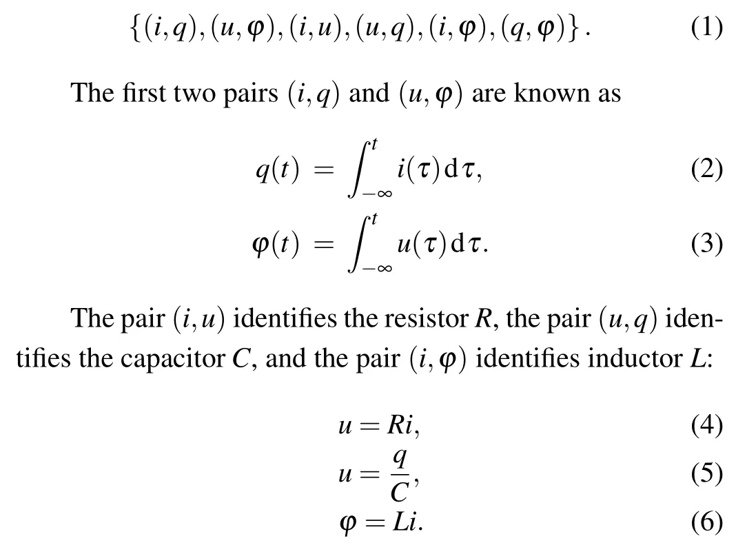
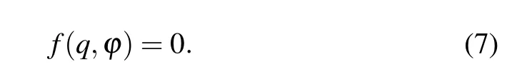
Leon O. Chua could not find a passive circuit element which can directly represent the relationship between the pair(q,φ). From the perspective of axiomatic completeness,Leon O. Chua argued that it was necessary to define a circuit element to represent the constitutive relation between them. He named the new circuit element memory-resistor(memristor),
2.1. Memristor
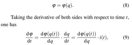
When the fluxφis a single-valued function of the chargeq,the above definition(7)can be rewritten as
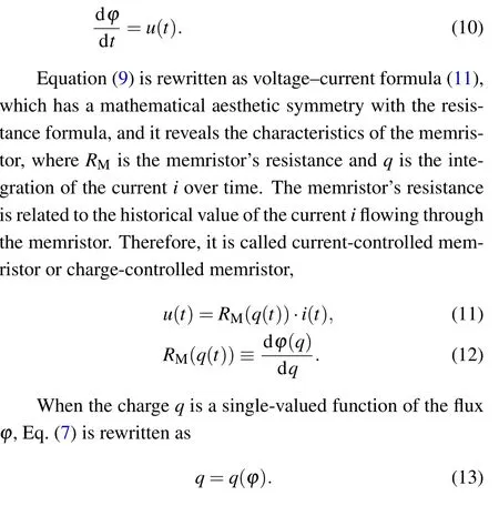
Following the derivation of current-controlled memristor, the voltage-current expression (14) of voltage-controlled memristor is obtained.RMis the memristor’s resistance and fluxφis the integration of the currentuover time. So, the resistance of the voltage-controlled memristor is related to the history of the voltage applied to the terminals of the memristor. Therefore,the current-controlled memristor is also called flux-controlled memristor

The resistor, current-controlled memristor and voltagecontrolled memristor have mathematically similar expressions for their formulas. The resistor is a memoryless element,and resistance is a constant. The resistanceRMof the currentcontrolled memristor is a function of chargeq, and its resistance varies with charge. The resistanceRMof the voltagecontrolled memristor is a function of fluxφ,and its resistance varies with fluxφ. Figure 1 shows the schematic diagrams of the circuit elements of resistor, charge-controlled memristor and voltage-controlled memristor.
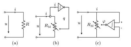
Fig.1. Circuit element schematic diagrams of resistor,current-controlled memristor, and voltage-controlled memristor. (a) The resistance of the resistor R is a constant,(b)the current-controlled memristor RM remembers the history of current i and varies with the charge q,(c)the voltagecontrolled memristor RM remembers the history of voltage u and varies with the flux φ.
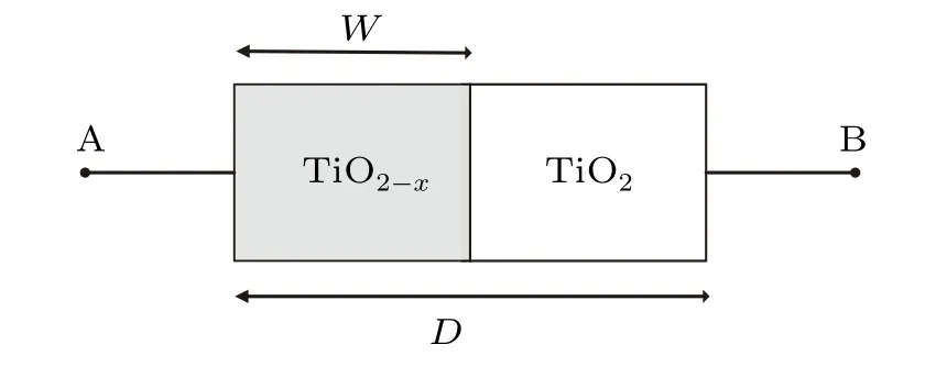
Fig.2. HP memristor structure.
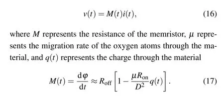
The memristor structure implemented by the Hewlett Packard (HP) Laboratories research team in May 2008 is shown in Fig. 2. It shows the structure of the HP memristor.The middle part is based on TiO2material. The material has a TiO2-xlayer doped with oxygen atom vacancies on the left side and an undoped TiO2layer on the right side. Assuming that the width of the body of the memristor isDand the width of the dopant layer isW, when excitation is applied to port 2 of the memristor, the current flowing through the memristor causes the oxygen vacancies in the TiO2-xlayer doped with oxygen vacancies to move towards the undoped TiO2layer,resulting in a change in the resistance of the memristor,and the direction of movement of the oxygen vacancies in the dopant layer is related to the direction of current flow through the memristor. It is assumed that the current flows from port A to port B in the forward direction and from port B to port A in the reverse direction. When the current flows in the forward direction, the movement of the oxygen vacancy causes the doping layer widthWto widen and the resistance of the memristor to decrease,and the memristor has a minimum resistanceRonwhenWis infinitely close toD. When the current flows in the opposite direction, the movement of the oxygen vacancy leads to a narrowing of the doping layer widthWand a high resistance of the memristor, and whenWis infinitely close to 0, the memristor has a maximum valueRoff. When the current is disconnected,the oxygen vacancy inside the resistor does not move and does not return to its initial state. It remains in the instantaneous state of the power failure. In HP memristor,the current–voltage relationship is expressed as
2.2. The Chua’s periodic table of all two-terminal circuit elements
By abstracting the resistor(4),inductor(6),capacitor(5)and memristor equations(11),(14),we get
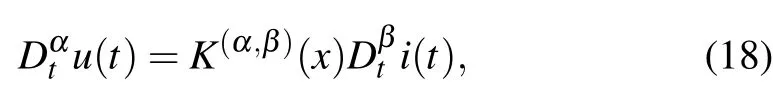
whereα,β >0 means numerical differentiation,α,β <0 means numerical integration,and

TheR,C,L, andMin Eq. (19) represent resistor, capacitor,inductor, and memristor, respectively. Usingαas thex-axis andβas they-axis, construct a Cartesian coordinate system to form the Chua’s periodic table[5]of all two-terminal circuit elements. In Fig.3, point(0,0)represents resistor, point(0,-1)represents capacitor,point(-1,0)represents inductor and point (-1,-1) represents memristor. A pair of (α,β)can represent a unique circuit element. The two elements(α,β)=(-1,-2)and(α,β)=(-2,-1)are memory capacitor(memcapacitor)and memory inductor(meminductor).
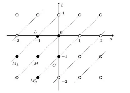
Fig.3. The Chua’s periodic table of all two-terminal circuit elements.
Imitating the derivation of the memristor in Subsection 2.1,we can obtain the following equations for the currentcontrolled and voltage-controlled memcapacitors:
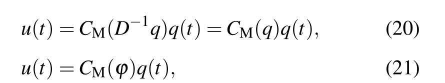
whereCMis a function of the fluxφor chargeD-1q(t).
Capacitor, charge-controlled memcapacitor and voltagecontrolled memcapacitor have similar mathematical expressions. The difference is that the value of the capacitor is fixed,while the charge-controlled and voltage-controlled memcapacitor have a memory effect. The charge-controlled memcapacitor remembers the integral value of the charge flowing through itD-1t q,the voltage-controlled memcapacitor remembers the history of the voltage change across the capacitor,the magnetic fluxφ. Their circuit schematic diagrams are shown in Fig.4.
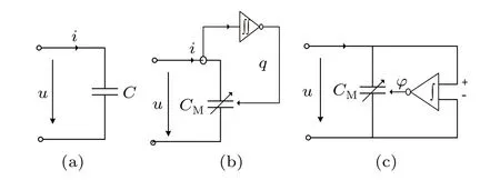
Fig. 4. Circuit element schematic diagrams of (a) capacitor, (b) currentcontrolled memcapacitor,and(c)voltage-controlled memcapacitor.
Imitating the derivation of the memristor in Subsection 2.1,we can obtain the equations for the current-controlled and voltage-controlled meminductors as
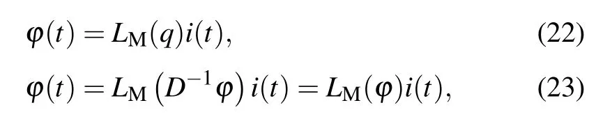
whereLMis a function of the fluxD-1t φor chargeq(t).
Inductor, charge-controlled meminductor and voltagecontrolled meminductor have similar mathematical expressions. The difference is that the value of the inductor is fixed,while the charge-controlled and voltage-controlled meminductors have a memory effect. The charge-controlled meminductor remembers the value of the chargeqflowing through it,and the voltage-controlled meminductor remembers the history of the flux around the meminductorD-1t φ. Their circuit schematic diagrams are shown in Fig.5.
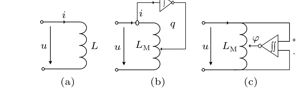
Fig. 5. Circuit schematic diagrams of (a) inductor, (b) current-controlled meminductor,and(c)voltage-controlled meminductor.
2.3. Application of memristors in chaotic systems
As memristors are non-linear devices, they can be used to construct chaotic circuits. In recent years, the design of chaotic systems based on memristors has become one of the hot directions in memristor research.The most common memristor chaotic system is the use of memristor to replace nonlinear components in a Chua’s circuit. Itoh and Chua[26]firstly used a flux-controlled segmented linear function as a model for a memristor,replacing the non-linear Chua’s diode in the Chua’s circuit,Bao Bo Cheng has made various attempts at chaotic systems, transient chaos in smooth memristor oscillator,[27]two-memristor-based Chua’s hyperchaotic circuit with plane equilibrium and its extreme multistability.[28]
Figure 6 shows the use of a current-controlled memristor and a voltage-controlled memristor instead of Chua’s diode in Chua’s oscillator,respectively. The memristor Chua’s oscillator has more complex dynamic behaviors than the traditional Chua’s oscillator.
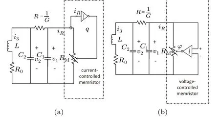
Fig. 6. Chua’s oscillator with (a) current-controlled memristor and (b)voltage-controlled memristor.
3. Fractional-order memristive device
Fractional calculus has many excellent properties. Fractional calculus is a kind of calculus whose operation order is non-integer, which has long-term memory, non-locality and weak singularity. Moreover,the fractional parameters can increase the extra degree of freedom of the system.αandβare required to be negative integers in the Chua’s periodic table,so some researchers consider using fractional calculus to extend the Chua’s periodic table and extendαandβto the real number field(Fig.7).
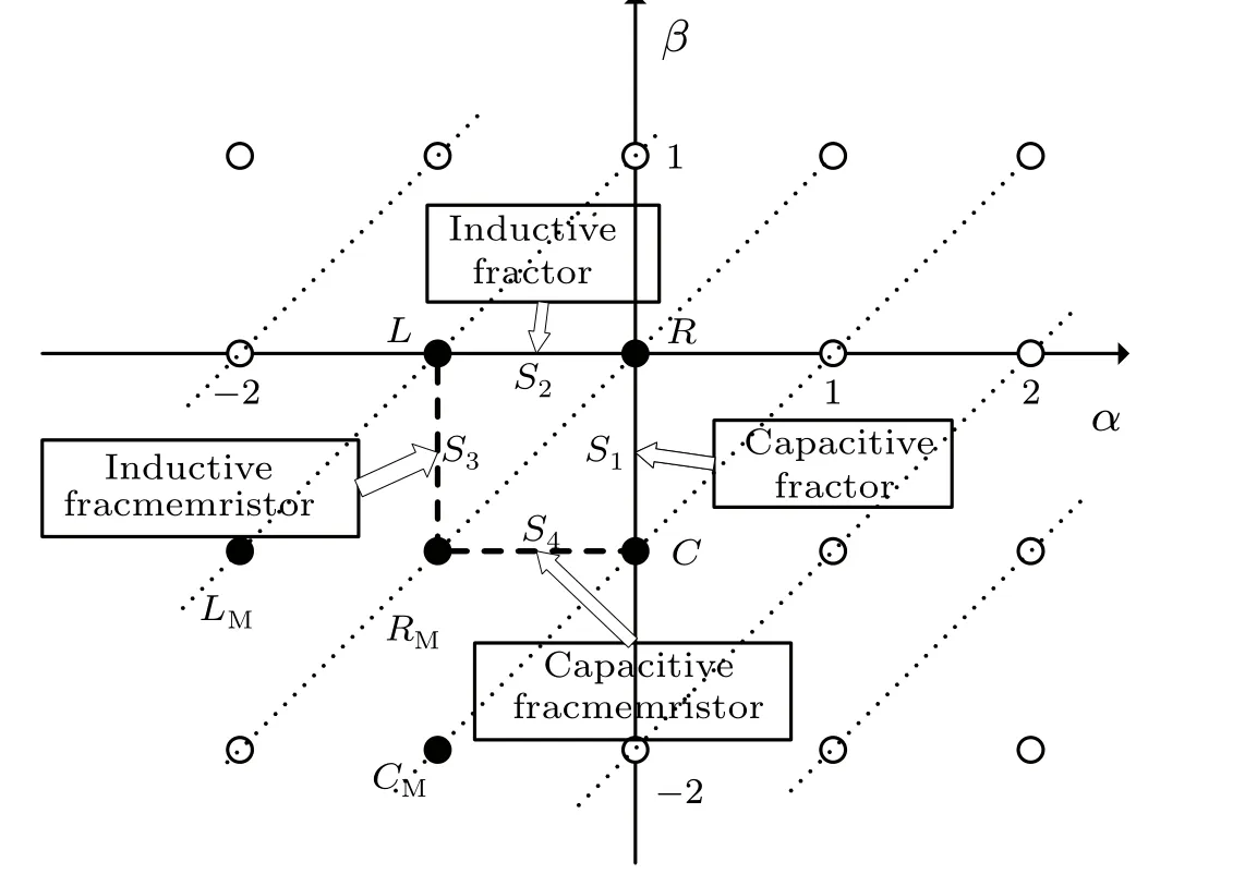
Fig.7. The fractional order of the Chua’s periodic table of all two-terminal circuit elements.
3.1. Introduction to fractional calculus
The fractional calculus came into being at the same time as the classical calculus. In 1695, the German mathematician Leibniz and the French mathematician L. Hoptial corresponded to each other to discuss the meaning of the derivative when it became 1/2. Fractional calculus is an extension of integer-order calculus, which extends the order of calculus from the integer domain to the fraction, even to the real number domain and complex number domain. The most commonly used is the Grunwald–Letnikov definition(GL definition).[9,29]It follows that

wheref(x)is a differ-integrable function,[a,x]is the duration off(x),andvis the order of fractional calculus.v >0 means the fractional derivative, andv <0 means the fractional integral.
3.2. Current fraction-order-controlled and voltage fraction-order-controlled memristor
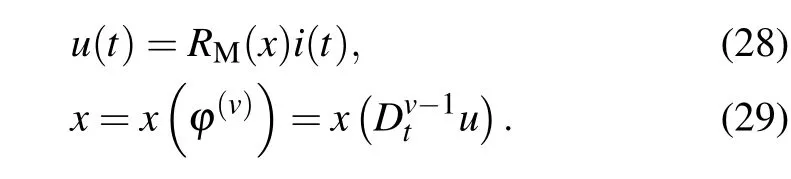
In Eq.(8),the integer-order current-controlled memristor,the fluxφis a single-valued function of the chargeq. Some researchers[10,30]have assumed that the chargeqis not the first-order integral of the current[Eq.(2)],but thev-order integral of the current [Eq. (25)], 0<v <1. By this method,a new memristive element, current fraction-order-controlled memristor (CFM), is proposed.q(v)in Eq. (25) means thev-order derivative of chargeq,not thev-power ofq.
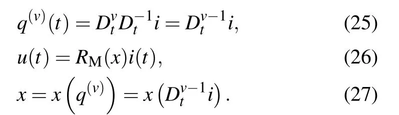
In Eq.(26),RMis the memristance of memristor,the same with integer-order current-controlled memristor. CFM follows the voltage–current relationship of the first-order currentcontrolled memristors(14),but the driving functionxis different.xof CFM is a function of thev-order derivative of chargeq(v).
When the driving functionxis a function of the fractionalorder derivative of fluxφ(v), a voltage fractional-ordercontrolled memristor(VFM)can be obtained as
Schematic diagrams of current fraction-order-controlled memristor (CFM) and voltage fractional-order-controlled memristor(VFM)are shown in Fig.8.The difference between CFM, VFM and memristor in Fig. 1 is small, except that the driving function of CFM is thev-order differential of chargeq(v),while the driving function of current-controlled memristor is chargeq, the driving function of VFM is thev-order differential of fluxφ(v), and the driving function of voltagecontrolled memristor is fluxφ.
By using the same extended method of current fractionorder-controlled memristor, current fraction-order-controlled memcapacitor (CFMC),[10]voltage fraction-order-controlled memcapacitor(VFMC),current fraction-order-controlled meminductor (CFMI) and voltage fraction-order-controlled meminductor(VFMI)can be deduced as
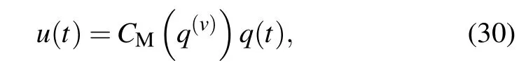
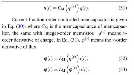
Current fraction-order-controlled meminductor is given in Eq. (32), whereLMis the meminductance of meminductor,the same with integer-order meminductor.q(v)meansv-order derivative of charge. In Eq. (33)),φ(v)means thev-order derivative of flux.

Fig.8. (a)Current fraction-order-controlled memristor,(b)voltage fractionorder-controlled memristor.
Circuit schematic diagrams of CFMC,VFMC,CFMI and VFMI are shown in Fig. 9. Schematic diagrams of CFMC,VFMC, CFMI and VFMI are almost the same as CMC,VMC, CMI and VMI, except the memorized charge changing from integer-order to fractional-order,and the memorized flux changing from integer-order to fractional-order.

Fig. 9. (a) Current fraction-order-controlled memcapacitor, (b) voltage fraction-order-controlled memcapacitor, (c) current fraction-ordercontrolled meminductor,(d)voltage fraction-order-controlled meminductor.
3.3. Capacitive fractor and inductive fractor
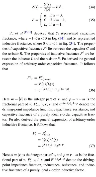
Applying the Laplace transform to both sides of resistor(4), capacitor (5) and inductor (6), we get Eq. (34), and the conclusion (35). Naturally, what are represented by the line segmentS1between resistorRand capacitorC, and the line segmentS2between resistorRand inductorLin Fig.4.
3.4. Capacitive and inductive fracmemristor
Another question, what are represented by the line segmentS4between memristorRMand capacitorC, and the line segmentS3between memristorRMand inductorLin Fig.9? Pu[12–14]gives the derivation.S3stands for inductive fracmemristor andS4stands for capacitive fracmemristor.
Reanalyze the memristor Eq.(11)from a signal and system viewpoint. We rewrite the current-controlled memristor formula to obtain
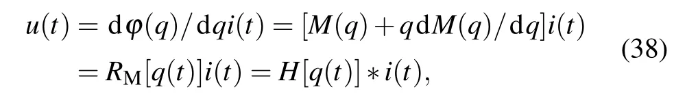
where symbol* denotes convolution, andH[q(t)] denotes the transmission function of a memristor. We getu(s) =r[q(s)]i(s),by implementing a multiplication in Laplace transform domain.r[q(s)] =L{H[q(t)]}is the reactance of this memristor. We have derived a general expression for the capacitive factor(36)and inductive factor(37)in Subsection 3.3.


Fig. 10. (a) Current-controlled capacitive fracmemristor and (b) voltagecontrolled capacitive fracmemristor,where means the v-order capacitive fracmemristance.
Following the capacitive fracmemristor modification above, we replace impedancerin inductive factor (37) withr[q(s)]andr[φ(s)],
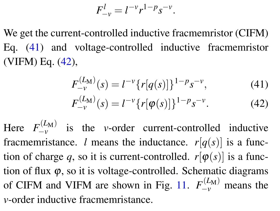
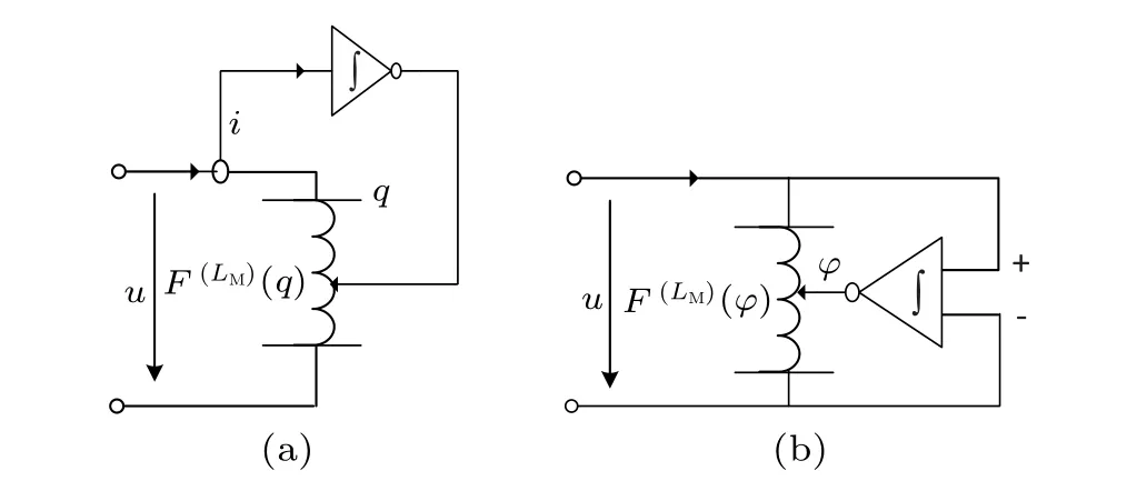
Fig. 11. (a) Current-controlled inductive fracmemristor and (b) voltagecontrolled inductive fracmemristor, where ) means the v-order inductive fracmemristance.
3.5. Impact of fractional order on the performance of fracmemristor
Without loss of generality,let us take a current-controlled capacitive fracmemristor as an example to analyze the electrical characteristics of the fracmemristor. Let us assume that the input causal current sourcesI(t)=sin(at)u(t)applied across a memristor and a fracmemristor are identical,whereais frequency. Let us illustrate the effect of the fractional-ordervon the electrical characteristics of a fracmemristor. Let us set the frequencya=1 rad/s and the time duration ofI(t) be equal to 6π. To illustrate theV–Icurves of the memristor and the fracmemristor in the same plot,the experimental values of the fracmemristor are divided by 1000. To avoid completely overlapping theV–Icurve of a fracmemristor with that of memristor and inconvenience of demonstration,let us setv=0.01,whenv=0.Thus,theV–Icurve of the idealv-order capacitive fracmemristor can be shown in Fig.12.
From Fig.12,we can observe that if the initial state of an ideal capacitive fracmemristor is zero and it is stimulated by a bipolar periodic signal with zero starting value. In Fig.12(a)when the fractional-orderv →0,an ideal capacitive fracmemristor degenerates to an ideal memristor. In Fig. 12(c),V–Icurve of an ideal 1/4-order capacitive fracmemristor has also a pinched hysteresis loop start from the original point of (0,0). However, pinched point of the multiple-valued Lissajous curves is no longer fixed at the point of (0, 0). In Fig. 12(g),when the fractional-orderv >2/3, the pinched point disappears.Electrical characteristics of an arbitrary-order fracmemristor depend on the convolution of its input current history and its fractional calculus. Thus, a capacitive fracmemristor and inductive fracmemristor can be considered in a certain way as a nonlinear interpolation of the memristor and capacitor and that of the memristor and inductor,respectively. Thus,the fingerprints of an arbitrary-order fracmemristor is different from that of a memristor.

Fig.12. Curve of ideal v-order capacitive fracmemristors: (a)0.01-order one;(b)0.1-order one;(c)1/4-order one;(d)1/3-order one;(e)1/2-order one;(f)2/3-order one;(g)3/4-order one;(h)1-order one.
3.6. Application of fracmemristors in chaotic systems
While scholars have investigated the use of memristors to replace Chua’s oscillator, there has also been research into the use of fractional order memristors to replace the nonlinear components in Chua’s chaotic circuits. In 2010,Ivo[31]firstly applied a current fractional order controlled memristor to the Chua’s chaotic circuit, replacing the Chua’s diode in the Chua’s chaotic circuit with a current fractional-order controlled memristor. A schematic diagram is shown in Fig. 13,whereFdenotes the current fractional order controlled memristor. In addition to replacing the non-linear components,Radwanet al.[31–33]changed the set of partial differential equations of the Chua’s chaotic circuit to fractional order as well, and the system exhibited more transient properties than the Chua’s chaotic circuit.
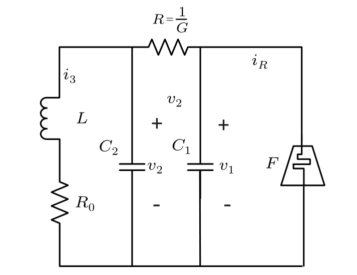
Fig.13. Chua’s oscillator with fracmemristor.
4. Conclusion
This paper introduces the development process of memristor,memcapacitor and meminductor in detail,and gives the related mathematical derivation from integer-order Chua’s periodic table to fractional-order Chua’s periodic table. Currently, there have been a lot of relevant studies on memristor controlled by fractional-order current or voltage, but few follow-up studies have been conducted on fracmemristor. Fracmemristor has many aspects to be studied, including: (1) basic properties, such as voltage–current characteristics,voltage step response,current step response,frequency characteristics,system properties,power consumption,and index definition; (2) application circuit, such as memory resistance in the analog-to-digital converter,digital-to-analog converter, sample holder, oscillator, modulation and demodulation circuit,power amplifier circuit,high frequency small signal amplifier circuit and other possible application potential;(3) chaotic system, such as the study of the characteristics of the chaotic system and circuit constructed by the memristor,and explore its application potential in information encryption and transmission;(4)neural network,such as the synaptic circuit, neuron circuit and the characteristics of neural network circuit composed of fracmemristor and its related theory and practice research; (5)simulator: continue to study the analog circuit realization of fracmemristor, especially the realization of simpler analog circuit;(6)digital realization:study the digital system realization of fracmemristor,and improve the highest frequency of its processing signal; (7) the simulation of natural phenomena and processes: excavate whether the phenomena and processes of existing systems in nature have the mathematical characteristics of memristor, and excavate the existence of fracmemristor in nature; (8)physical realization:excavate the physical realization of fracmemristor,and explore the possibility of realization from the perspectives of materials,biology,chemistry,etc.
Acknowledgments
Project supported in part by the National Natural Science Foundation of China (Grant No. 62171303), China South Industries Group Corporation(Chengdu)Fire Control Technology Center Project(non-secret)(Grant No.HK20-03),and the National Key Research and Development Program Foundation of China(Grant No.2018YFC0830300).
猜你喜欢
杂志排行
Chinese Physics B的其它文章
- Ergodic stationary distribution of a stochastic rumor propagation model with general incidence function
- Most probable transition paths in eutrophicated lake ecosystem under Gaussian white noise and periodic force
- Local sum uncertainty relations for angular momentum operators of bipartite permutation symmetric systems
- Quantum algorithm for neighborhood preserving embedding
- Vortex chains induced by anisotropic spin–orbit coupling and magnetic field in spin-2 Bose–Einstein condensates
- Short-wave infrared continuous-variable quantum key distribution over satellite-to-submarine channels