A selected review of vortex identification methods with applications *
2018-10-27YuningZhang张宇宁XuQiu裘勖FeipengChen陈飞鹏KaihuaLiu刘凯华YuningZhang张宇宁XiangruiDong董祥瑞ChaoqunLiu
Yu-ningZhang(张宇宁),XuQiu(裘勖),Fei-pengChen(陈飞鹏),Kai-huaLiu,(刘凯华),Yu-ningZhang(张宇宁),Xiang-ruiDong(董祥瑞),ChaoqunLiu
1. Key Laboratory of Condition Monitoring a ndControlfo rPowe rPlant Equipm ent(Min istryofEdu cation),School of Energy, Power andMechanicalEngineering,NorthChinaElectricPowerUniversity,Beijing 102206 , China
2. BeijingSo uth-to-North Wat erDiversionTu anchengLak eMan agementO ffi ce,Beijing100195 ,China
3. College ofMechanicalandTransportationEngineering,ChinaUniversityofPetroleum-Beijing,Beijing 102249, China
4. Beijing Key Laboratory of ProcessFluidFiltrationandSeparation,ChinaUniversityofPetroleum-Beijing,Beijing 102249, China
5. National Key Laboratory of Transient Physics, Nanjing University of Science and Technology, Nanjing 210094,China
6. Department of Mathematics, University of Texas at Arlington, Arlington, Texas, USA
Abstract: In the present review, recent progress on the vortex identification methods are introduced with a focus on the newly proposed omega method (Ω method).The advantages of Ω method are summarized with many illustrating examples.Furthermore, comparing with other existing methods (e.g., Q criterion and 2λ criterion), one of the characteristics of Ω method is its independence on the chosen threshold values for vortex identifications.The important parameters involved for the practical applications of Ω method are further discussed in detail together with the physical interpretation of the Ω and some suggestions of the future work.Other emerging topics (e.g., Lagrangian coherent structure and Rortex) are also introduced with comments.
Key words: Vortex identification, turbulence generation, Ω method, vorticity concentration, Galilean invariant, Rortex
Authorsʼ biography
Yu-ning Zhang (1983-), Associate Professor of School of Energy, Power and Mechanical Engineering,North China Electric Power University, Beijing,China.He obtained Bachelor of Engineering in Power Engineering and Engineering Thermodynamics (2006)and Master of Engineering in Fluid Machinery and Engineering (2008) both in Tsinghua University,Beijing, China and Ph.D.in Fluid Dynamics (2013),The University of Warwick, UK.His primary research interests include vortex identification, cavitation,high-speed photography and hydraulic machineries.He has published over 40 papers on high-profile international journals as leading/corresponding author.He has given over ten invited talks on leading conferences.He also serves as the Chairman of International Cavitation Forum 2016, an Associate Editor of IET Renewable Power Generation, member of scientific/ organizing committee of many well-established international conferences.
Chaoqun Liu (1945-), Distinguished Professor of Department of Mathematics, University of Texas at Arlington, Arlington, Texas, USA.He also servers as the Director of Center for Numerical Simulation and Modeling.He obtained Bachelor of Science in Fluid Mechanics (1967) and Master of Science in Computational Fluid Dynamics (1981) both in Tsinghua University, Beijing, China and Ph.D.in Applied Mathematics (1989), University of Colorado at Denver, USA.His fields of interest include vortex identification, numerical analysis, multigrid, multilevel adaptive methods, computational fluid dynamics,direct numerical simulation, large eddy simulation,high-order numerical scheme, numerical combustion and software development.He has published over 200 journal/conference papers together with eight books.He served as the Principal Lecturer of many short courses relating with the turbulence generation and sustenance in boundary layer held both in USA and China.He was also the Chairman of the first (1997)and the third (2001) AFOSR International Conference on Direct Numerical Simulation and Large Eddy Simulation.
Introduction
Vortex is a quite common phenomenon in the natural world (e.g., vortex induced by the flying hawkmoth[1]) and our daily life.Furthermore, vortex is widely involved in a wide range of flows in the practical engineering applications including ultrasonic biomedical treatment[2-3], airplane wing aerodynamics[4], shock-wave induced flow[5], natural convection[6], wind turbine dynamics[7-9], jetting phenomenon[10].Specifically, vortex is also strongly related with various kinds of hydrodynamics including cavitation[11], pump performance[12-13], and tip clearance vortex[14-15].For example, vortex related cavitation phenomenon include bubble-particle interactions in the silt-laden flow[16-20], wave propagation in bubbly flow[21-22], collapsing dynamics[23-26], acoustic bubble dynamics (e.g., chaotic oscillations[27], nonlinear oscillator[28-29], damping[30]and stability[31-32]), and cavitation inception[33-34].Furthermore, many industrial-level flows e.g., reversible pump turbine for largescale energy storage, also suffer from many vortex induced phenomenon including rotating stall[35],vibrations[36], pressure fluctuations[37-41], tip clearance vortex[42-43], hysteresis[44-45], hump stability[46-47].Hence, methods for vortex identification are a critical issue in fluid mechanics especially hydrodynamics for revealing the underlying vortical structures with further improvement of the theory.
In the literature, this topic has been intensively addressed by many researchers[48-68]with various kinds of vortex identification methods proposed (e.g.,Qcriterion[56]and2λcriterion[58]).For a recent review, readers are referred our previous paper with a clear classification of the existing methods with applications examples[48].Recently, Liu and his collaborators proposed several new vortex identification methods[49-55]with plenty of applications in the literature[69-70].In this review, recent progress on the vortex identification methods are selected with a focus on the newly proposed omega method.A brief introduction of each section of the present review will be given as follows.In Section 1, several typical vortex identification methods are briefly introduced with some comments.In Section 2, the omega method(Ωmethod) is introduced with a summary of its advantages based on comparisons with other existing methods (e.g.,Qcriterion[56]and2λcriterion[58]).In Section 3, several demonstrating applications of theΩmethod are given and interpreted.In Section 4,several possible future works are given and discussed in detail with a physical interpretation of theΩand other emerging topics (e.g., Lagrangian coherent structure and Rortex).In Section 5, the concluding remarks of the present review are given together with the available code for theΩvortex identification.
1.An overview of typical vortex identification methods
In this section, several well-employed vortex identification methods will be briefly introduced.For the convenience of the further discussions, the characteristic equation of velocity gradient tensor is given as

HereP,Q,Rare three invariants of the velocity gradient tensor.Furthermore, the velocity gradient(∇V) could be decomposed into two parts as follows
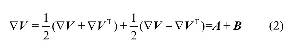
whereAis the symmetric part,Bis the antisymmetric part.
1.1 Q criterion
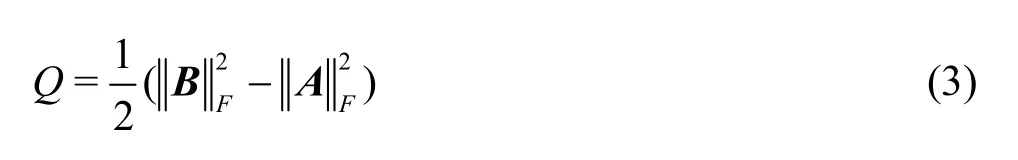
Qcriterion is directly derived based on the second invariantQof the velocity gradient tensor given in Eq.(1) with the following expression[56]
1.2 λ2 criterion
The2λcriterion defines the vortex of the fluid flow as the local pressure minimum of the certain fluid domain[58].If one defines three real eigenvalues ofA2+B2asλ1,λ2andλ3with the following order (λ1≥λ2≥λ3), theλ2criterion corresponds to the existence of two negative eigenvalues (i.e.,λ2<0)[58].
1.3 Δ criterion
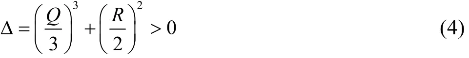
Based on the critical point theory, Chong et al.[57]defined the vortex region with
1.4 Comparisons between different existing methods
In this section, a brief note on the comparisons between different existing methods will be given.The aforementioned methods all require to adjust the threshold values in order to deliver a proper result.Hence, the common limitation of the aforementioned three methods is their dependence on the above thresholds.Specifically, different thresholds may lead to different vortex structures for a given flow case.However, a rigorous criterion for the determination of this threshold is still absent.
Figure 1 shows the vortex identification results by the2λcriterion (a) andQcriterion (b) for the Taylor-Görtler vortical structures.As shown in Fig.1,there are no essential difference among the two for this case if a proper threshold is chosen.Similar findings were also reported by the Dubief and Delcayre[71](referring to Fig.5 of the Ref.[71]).

Fig.1 Comparison of the vortex identification by the 2λ criterion (a) and Q criterion ((b), identified with-2Q).Velocity vectors are also shown for the comparions.This figure was adapted from Figs.5(a), 5(c) of Fraňa et al.[72]
2.Ω method
2.1 Description of Ω method
The definition ofΩcan be described as follows[49]:
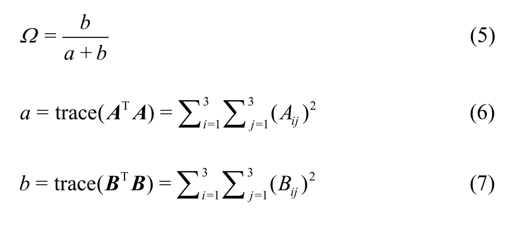
whereaandbare the square of Frobenius norm ofAandB(referring to Eq.(1)).For the practical calculation,Ωis further modified as follows[49]

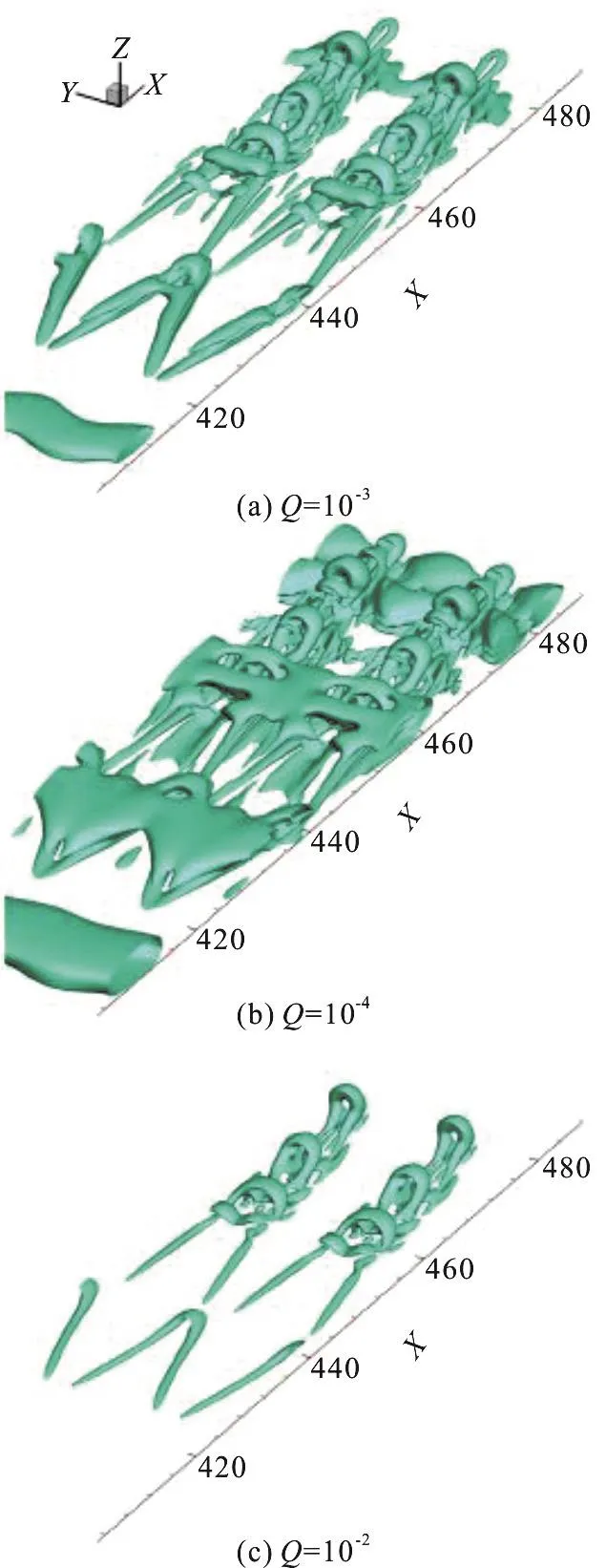
Fig.2 An illustrating example of the influences of the Q values on the vortex identification.Here, physical identification of the T-S wave is selected for the discussions.This figure was adapted from the Fig.3 of Liu et al.[49]
where ε is a small positive number employed to avoid the division by zero.For detailed determination of parameter ε, readers are referred to Section 2.2.
Different with other existing vortex identification methods, the Ω method has a normalized value ranging from 0 to 1 since both a and b are not negative.Meanwhile, new Ω method has a clear physical meaning through the definition of the vortices corresponding to the vorticity overtaking the deformation.
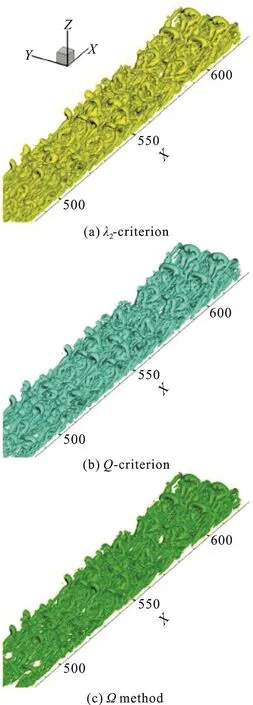
Fig.3 Comparison for the vortex identification of the T-S wave.The chosen values of the Q criterion (Q =10-3) and 2λ criterion 32 (λ = -10-3 ) are optimized based on the authorʼs experience.This figure was adapted from the Fig.5 of Liu et al.[49]
2.2 Advantages of Ω method
The advantages of Ω method could be summarized as follows.Here, vortex identifications of the T-S wave and the micro wave generator are selected as examples for discussions.
Figure 2 shows an illustrating example of the influences of the Q values (Q=10-3, 10-4and 10-2respectively) on the vortex identification.One can find that the choice of the Q values will strongly affect the identified vortex.However, it is quite difficult to determine an appropriate threshold value for the vortex identification based on the Q criterion.Similar dilemma also happens for other identification methods (e.g.,2λ criterion).
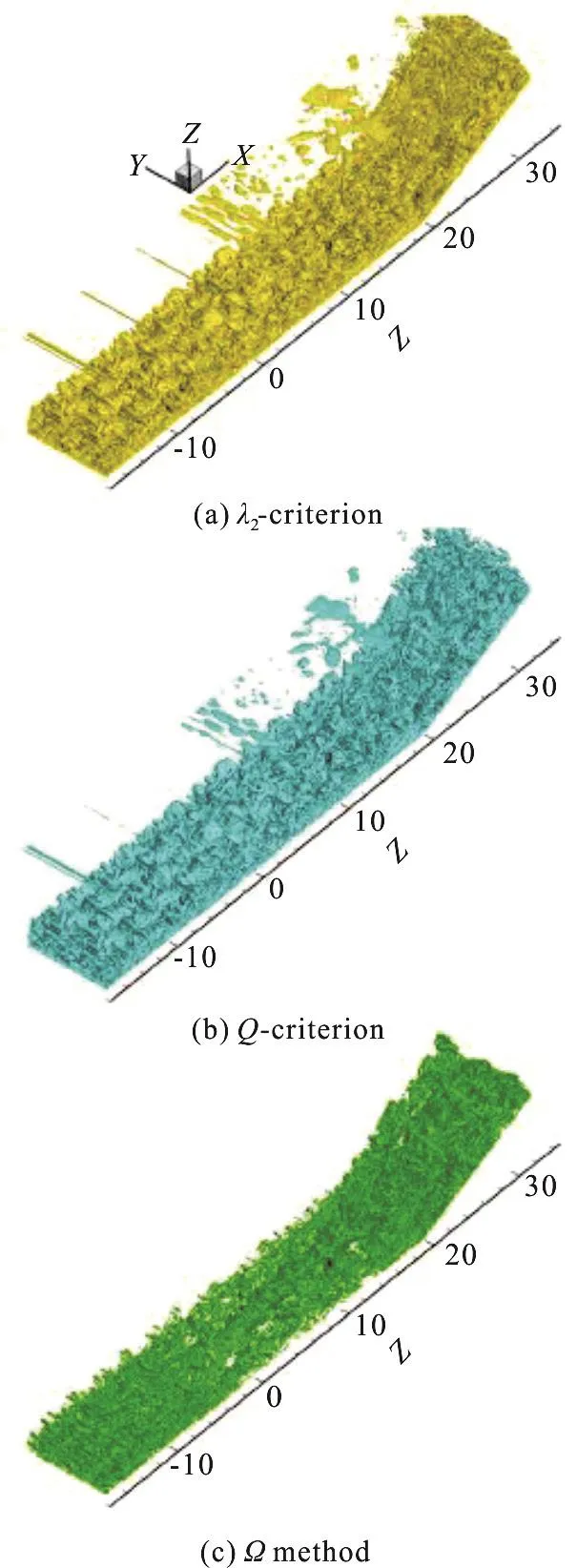
Fig.4 Comparison for the vortex identification of micro wave generator.The chosen values of the Q criterion (Q =10-3 ) and λ2 criterion (λ = -10-3) are optimized based on the authorʼs experience.This figure was adapted from the Fig.9 of Liu et al.[49]
For the Ω method, the identified vortex is universal.Figures 3, 4 show the comparisons between the λ2/Q criterions and the Ω method for the vortex identification of the T-S wave and micro wave generator respectively.The chosen values of the Q criterionand λ2criterionare optimized based on the authorʼs experience.It could be found that without the subjective adjustment of the values (e.g., the process involved for the choice of a proper threshold during the usage of theλ2|Qcriterions), theΩmethod could successfully capture the primary characteristics of the vortex structure.As shown in Figs 5, 6, the results of vortex identification is quite insensitive to the chosen values ofΩ.

Fig.5 The influences of the values of Ω on the Λ vortex identification.This figure was adapted from the Fig.6 of Liu et al.[49]

Fig.6 The influences of the values of Ω on the vortex identification during the boundary layer transition.This figure was adapted from the Fig.7 of Liu et al.[49]
Furthermore, during the practical usage of theQcriterion, for the large values ofQ, only strong vortex will be captured with the weak vortex skipped while for the small values ofQ, there are too many weak vortex, leading to the smear of the vortex structure.However, for theΩmethod, both the strong and weak vortex could be captured simultaneously (as shown in Figs.3, 4).
For the completeness, the influences of the parameterεin Eq.(8) on theΩmethod will be further discussed.In our previous paper, a proper determination method of parameterεwas proposed such as[50]

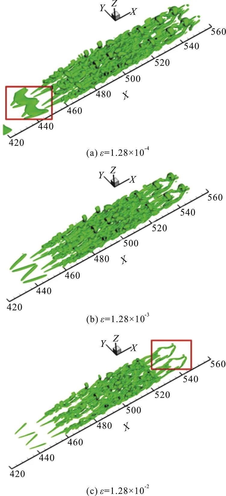
Fig.7 Influences of values of ε on the vortex identification of the boundary layer transition.This figure was adapted from the Fig.1 of Dong et al.[50]
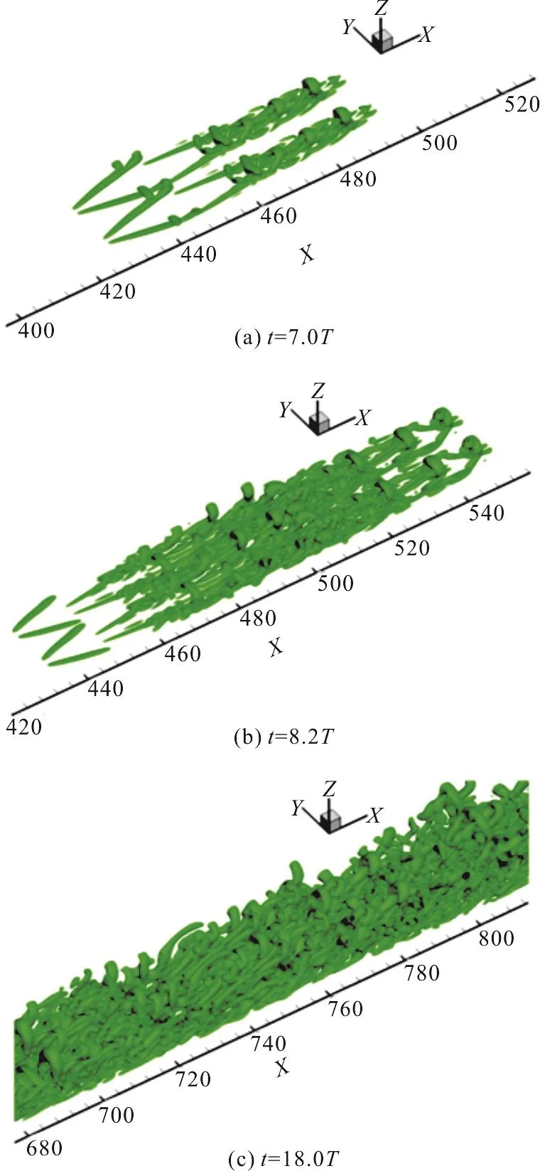
Fig.8 Vortical structure visualization using the proposed determination method in different time steps during the boundary layer transition.This figure was adapted from the Fig.3 of Dong et al.[50]
Figure 7 shows the tests of theεdetermination method for the vortex identification att=8.2Tduring the boundary layer transition on a flat plate based on a high order direct numerical simulation(DNS).Figure 7(b) shows the vortex identification by employing Eq.(9) for the determination ofε.For the comparisons, smaller and larger values ofεare also chosen to visualize the vortex structures as shown in Figs.7(a), 7(c).In Fig.7(a), too many clouds is shown without a clear demonstration of the vortex structure while in Fig.7(c), some significant vortex structures will not be identified.Hence, the Eq.(9) is a proper choice for the determination ofε.Figure 8 further shows the identified vortical structure of the boundary layer transition by theΩmethod in different time steps.As shown in Fig.8, many typical vortical structures and its time-domain evolutions could be well identified.
3.Applications of Ω method
3.1 Vortex shedding in the wake flow of moving bodies
The vortex shedding dynamics induced by the activities of the human bodies plays an important role on the determination of the contaminant dispersions(e.g., bacteria) in indoor environments especially hospital inpatient wards, airline cabin and certain factories.Hence, the identification of the vortex patterns generated by the movement of the human bodies is essential to fulfil the above targets.
Recently, Tao et al.[69]applied theΩmethod for the identification of vortices in the wake flow of two typical types of moving manikins (representing the human bodies).For the completeness, two scaled manikins with different shapes (slim and larger ones respectively) were carefully manufactured using 3-D printing technology.Meanwhile, an experimental study using smoke visualization system was also conducted with the results compared with the omega identification ones.
Figure 9 shows the comparisons of the vortex structures of the wake flows induced by the two kinds of the moving manikins in different time steps.Figure 9(a) shows the slim one and Fig.9(b) shows the larger one.Both the smoke visualization (upper subplots)and the vortex identification through theΩmethod(lower subplots) are all shown.Colors in the figure represent the velocity magnitude.Generally speaking,the vortex identification through theΩmethod agrees well with the experimental observation especially in terms of the separation angle at the manikin heads and the primary patterns of the vortex structures.Furthermore,Ωmethod could also reveal the sheared wake and the entrained flow behind the moving manikins.
3.2 Drifting snow in the turbulent atmosphere boundary layer
In the turbulent atmosphere boundary layer with high latitudes, drifting snow frequently occurs as an important type of aeolian multiphase flow.The study of the drifting snow is of great importance from the viewpoints of the glaciological and the hydrological aspects.For example, the drifting snow could lead to a re-distribution of the snow layer, which is critical for the evaluation of possible natural geological hazards.Furthermore, through the dispersion and the transportation of the snow particles, the mass of the ice sheets will be affected, leading to the temporal or spatial imbalance.
Recently, Huang and Wang[70]established a 3-D drifting snow computational model based on the large eddy simulation with a large amount of snow particle trajectories tracked.For the vortex identification,Ωmethod is employed to further reveal the vortex structures in the fully developed turbulent boundary layer.Figure 10 shows the primary vortex structures in the turbulent boundary layer with snow particles.As shown in Fig.10(b), regions with high concentrations of the snow streamers are of great values of vortical vorticity.Hence, the formation of the snow streamer is closely related with the local fluid vortex flow.This is quite different with the sand streamer, for which the strong surface wind is of great importance for the sand distributions.

Fig.10 A demonstration of the vortex identification with Ω method in fully developed turbulent boundary layer with snow particles.(a) The vortex structures in the turbulent boundary layer.(b) The distributions of vortical vorticities larger than 2 000 s-2 (green patches) together with the snow particles (black points).This figure was adapted from the Fig.8 of Huang and Wang[70]
3.3 Vortices in the reversible pump turbine
Reversible pump turbine are widely employed in the pump hydro energy storage power plant.However,currently, the flow-induced severe instability are greatly affecting the daily normal operations of the units, leading to many unplanned stops of the power plants.Because of the frequent shifts among various kinds of working modes, there are a large amount of vortices shown in the flow passage of the reversible pump turbine.Hence, the vortex identification in the reversible pump turbines is important to reveal the inside vortex flow structures with further improvement of the design.

Fig.11 The vortices identified by Ω method in the reversible pump turbine at 21° guide vane opening.This figure was adapted from Fig.3 of Zhang et al.[38]
Generally speaking, five operational modes(including the turbine mode, the runaway mode, the turbine brake mode, the zero-flow-rate mode and the reverse pump mode) are usually involved during the daily operations of the turbine.Hence those five modes will be selected for the analysis of vortices using theΩmethod as shown in Zhang et al.[38].Figure 11 shows the primary characteristics and the distributions of vortices inside the turbine during five different working modes.As shown in Fig.11, for the turbine mode, limited vortices are shown in the impeller while for the reverse pump mode, a large amount of vortices occupies the majority of the turbine.Figure 12 further shows a quantitative comparison among five different working modes in terms of the vortices area.Among them, the zero-flow-rate mode is of the largest vortices area and the reverse pump mode is the second one.For other working modes, the difference is marginal.According to Fig.11,Ωvortex identification method could capture both weak (e.g., Fig.11(d)) and strong vortices (e.g.,Fig.11(e)) in the whole passage of the reversible pump turbines.
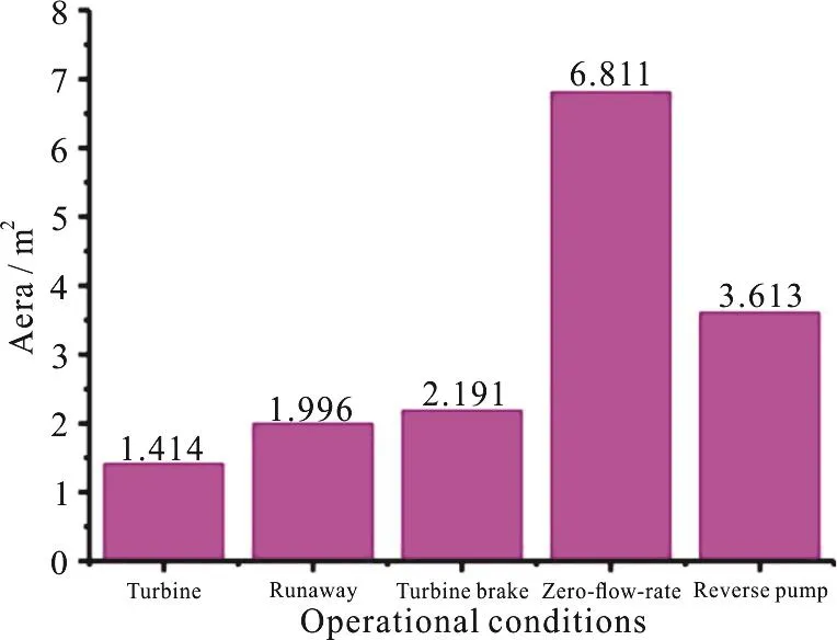
Fig.12 A quantitative statistics of vortices areas identified by the Ω method for five different operational conditions of the reversible pump turbine at 21° guide vane opening.This figure was adapted from Fig.4 of Zhang et al.[38]
4.Future works
4.1 Determination of the parameter in Ω method and the interpretation of its physical meanings
In theΩmethod, the determination of the parameterεis quite essential because it will affect the results of the vortex identification.As shown in Eq.(8), the initial intention for the addition of the small positive parameterεis to avoid the division by zero.Such treatment only involves the numerical details.Here, some emerging ideas will be given and discussed to further explore the physical meanings ofΩmethod together with the parameterε.
For the convenience, theΩvalue for the case without the involvement of the parameter is defined as 0Ωwith the following expressions

The addition of the parameterεcould be fulfilled through revisions of two parts (theaandbrespectively).For the convenience, the addition of theεwill be further discussed in terms of non-dimensional forms.The first method involves the revisions of terma(deformation term) such as

with

Here Δais the non-dimensional parameter relating with deformation term.
If one draw an analogy between theΩdefinition and the concentration of a mass (e.g., the concentration of sugar in the water), many similarity could be revealed.For the readersʼ convenience, a new term “vorticity concentration (VC)” is newly proposed.The pure deformation can be defined as flows with VC=0 while the rigidly rotational flow is defined as flows with VC=1.According to theΩcriteria, the vorticity overtakes the deformation when the “vortex” is formed[49].It means that the vortex is formed in flows when VC>0.50.Hence,with the aid of the concept of VC, the physical meanings of the vortices could be clearly shown.Alternatively speaking, the addition of termaεin the Eq.(11) refers to the decrease of the vorticity concentration, leading to the decrease of theΩvalues.Quantitatively speaking, the above formulas could be revised as:
or
Here Δcis the non-dimensional parameter reflecting the variations of theΩdue to the addition of the parameterεain Eq.(11).

Fig.13 The variations of the Δc and Ω with the parameter Δa
Figure 13 shows the variations of the ΔcandΩwith the parameter Δa.In this example,0Ωis set to be 0.52 for the convenience of discussions.With the increase of Δa, Δcincreases dramatically while theΩdecreases from the 0.52 to 0.32.Especially,for Δalarger than 10-2, the decrease rate ofΩis quite significant (with a quick dilution of the vorticity).
Alternatively, the other method for the addition ofεinvolves the revisions of the vorticity termbas follows:
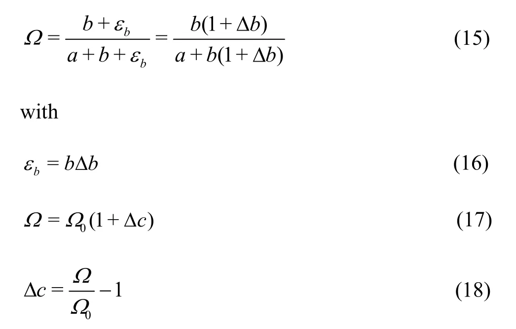
On the contrary of the first method, the revisions of termb(bεin the Eq.(15)) corresponds to the increment of the vorticity concentration.Different with the previous case, the revisions of termbinvolves the change of both numerator and denominator.Figure 14 shows the variations of the ΔcandΩwith the parameterΔb.With the increase of Δb,both ΔcandΩincrease (corresponding to the vorticity concentration enhancement).In the future,more examples relating with the parameter determination ofεwill be given.

Fig.14 The variations of the Δc and Ω with the parameter Δb
Hence, as a summary, for different methods of addition ofε(aεin Eq.(11) orbεin Eq.(15)), it could avoid the possible numerical errors but with some other effects, which should be noticed during the practical applications.With the revisions of the deformation term (εa), the weak vortex will be skipped and could not be clearly identified.On the contrary, with the revisions of the vorticity term (εb),some structures will be identified as the “fake” vortex,leading to the incorrectness.
4.2 Lagrangian coherent structures
Generally speaking, the trajectories of most typical fluid particles involved in the natural or industrial flows is highly dependent on the initial conditions.This feature causes great difficulties for the development of computational fluid models (e.g.,in terms of fluid motion predictions and comparisons)and also the experimental observations.However,different with the uncertainties of the single trajectory,Lagrangian coherent structures (LCSs) usually exists with a robust pattern and frames[65-68], which could be employed to represent the typical fluid structures.
Recently, LCSs has made significant progress with experimental confirmations, coherent eddy transport ocean models and short-term forecasting potentials.For a comprehensive review, readers are referred to Haller[68].In the future, for industrial-level vortex flows (e.g., the aforementioned turbines), a 3-D LCSs is highly desirable and the computational efficiency is of great concern for those cases.
4.3 Rortex
In order to identify the vortical structures more precisely, Liu et al.[51,54-55]proposed a new vortex vector (named as “Rortex”) with a rigorous mathematical proven of its existence and an accurate definition.Comparing with the vortex, a clear relationship between the Rortex and the rigid fluid rotation is established.For the verifications of the effectiveness of the Rortex, several demonstrating examples were given including both the 2-D flow (e.g., Couette flow,rigid rotational flow) and the complex 3-D flow (e.g.,boundary layer transition on a flat plate).Moreover,many Rortex based vortex structures could be also utilized for the vortex identification e.g., Rortex vector field, Rortex lines and Rortex tubes.
4.4 Differences between vortex identification and visualization
There are great differences between the vortex identification and the vortex visualization.For the vortex identification, the main purpose is to identify the correct vortex structures for the various kinds of flows.However, for the vortex visualization, the primary target is to visualize the already identified vortex with a well-established view.Hence, the difference between theΩmethod and the other methods(e.g., theQcriterion and2λcriterion) is quite significant for the vortex identification.OnlyΩmethod could identify the correct vortex structures because it can identify both the strong and weak vortex.For other methods, the identified vortex is strongly dependent on the given values of a certain criterion.For large values, only strong vortex is identified with many important vortex structure omitted.For small values, many weak vortex is identified with too much noises, leading to the useless of the identified results.It looks like an unachievable task to strike a balance between the two trends.The omega method provides a solution to this longstanding dilemma for the vortex identification.In the future, the identification of the weak vortex is an emerging topic (e.g., with 0.50<Ω< 0.52) in order to reveal some unobserved vortex structures (e.g.,various kinds of vortex during the turbulence structure generation and the time/space domain evolution).
5.Conclusions
In the present review, recent progress on the vortex identification methods has been critically selected with a focus on the newly proposedΩmethod.The advan- tages ofΩmethod are demonstrated through comparisons with other existing methods (e.g.,Qcriterion and2λcriterion).The important parameters involved for the practical applications ofΩmethod are further discussed in detail with many suggestions of the future work.The following concluding remarks could be given:
(1)Ωmethod overcomes the usage of the threshold values, leading to its independence of the userʼs subjective experience.
(2) The involved parameterεin theΩmethod is important for vortex identification and is quite worthy for the further investigation.
(3) More application examples ofΩmethod is quite necessary for extending its applications into broad ranges of flows.
TheΩcode (written both in Tecplot and Fortran as a supplementary material) is available through the following website:
https://link.springer.com/article/10.1007%2Fs11433-016-0022-6
Acknowledgements
This work was supported by the Science Foundation of China University of Petroleum, Beijing(Grant No.2462016YJRC003).We are very glad to take this opportunity to appreciate the fruitful discussions with Prof.Lian-di Zhou.
猜你喜欢
杂志排行

水动力学研究与进展 B辑的其它文章
- Call For Papers The 3rd International Symposium of Cavitation and Multiphase Flow
- Two-phase SPH simulation of vertical water entry of a two-dimensional structure *
- Tracer advection in an idealised river bend with groynes *
- Simulation of the overtaking maneuver between two ships using the non-linear maneuvering model *
- The effect of downstream resistance on flow diverter treatment of a cerebral aneurysm at a bifurcation: A joint computational-experimental study *
- Nonlinear dynamic characteristics of a multi-module floating airport with rigid-flexible connections *