Effect of internal sloshing on added resistance of ship*
2017-03-09MinGukSeoYonghwanKimDongMinPark
Min-Guk Seo, Yonghwan Kim, Dong-Min Park
1. Korea Research Institute of Ships and Ocean Engineering, Daejeon, Korea, E-mail:mgseo@kriso.re.kr
2. Department of Naval Architecture and Ocean Engineering, Seoul National University, Seoul, Korea
(Received August 20, 2016, Revised December 4, 2016)
Effect of internal sloshing on added resistance of ship*
Min-Guk Seo1, Yonghwan Kim2, Dong-Min Park2
1. Korea Research Institute of Ships and Ocean Engineering, Daejeon, Korea, E-mail:mgseo@kriso.re.kr
2. Department of Naval Architecture and Ocean Engineering, Seoul National University, Seoul, Korea
(Received August 20, 2016, Revised December 4, 2016)
The motion responses of ships carrying liquid cargo are affected not only by external wave excitation, but also by internal sloshing-induced forces and moments. Sloshing flow is coupled with the ship motion. This means the added resistance in waves may change when sloshing occurs inside the tank of the ship. In this study, the motion responses and added resistance of a ship, coupled with the sloshing-induced internal forces and moments are considered by using the linear potential theory. The three-dimensional Rankine panel method, in which the physical quantities are represented by using B-spline basis function, is applied. The sloshing flow of inner tanks is also simulated by using the Rankine panel method and linearized boundary value problem. To study the added resistance, a near-field method, which integrates the second-order pressure on a body surface, is applied. The model ship is a blunt modified Wigley model with two inner tanks. Numerical results obtained without inner tanks are compared with the experimental data, and then the effect of filling ratio of inner tanks on ship motion and added resistance are observed. The components that induce added resistance are examined, and the effects of surge motion on sloshing flow and added resistance are briefly considered. This study shows that the sloshing flow inside the inner tanks may significantly influence not only the motion responses, but also added resistance, especially, when the incident wave frequency approaches the resonance frequency of the sloshing flow.
Added resistance, sloshing, seakeeping, coupled effect, Rankine panel method
Introduction
The motion of liquid cargo vessels such as liquefied natural gas (LNG) carriers is affected by internal sloshing-induced forces and moments. conversely, the sloshing flow in inner tanks is excited by the vessel motion. In other words, sloshing motions inside tanks interact with vessel motion and these are closely coupled with each other. This coupling is important for two aspects of marine engineering: prediction of sloshing-induced loads on tank surfaces and effects on ship motion dynamics. The former plays an important role in the design for safe cargo containment system of LNG carriers and offshore structures dealing with liquid cargo. Violent sloshing flow in cargo holds can generate impulsive pressure that acts on the internal structure resulting in damage; therefore, LNG cargocontainment systems should be designed to endure sloshing-induced impact loads. The latter aspect is related mainly to ship stability and reduction in roll motion. The anti-rolling tank is the representative example of devices for dealing with such engineering problems.
Studies on sloshing-induced impact loads were conducted extensively in the 1970s and 1980s. Recently, the demand for the analysis of sloshing-induced impact load has been increaseding because of the use of numerous types of liquid cargo vessels, such as LNG carriers, large oil tankers, floating production, storage, and off-loading (FPSO), and floating storage and regasification units (FSRU). In the 1960s, a few studies were carried out on effects of coupling between sloshing flow and ship motions, and these mainly focused on anti-rolling tanks. These studies included investigations based on experiments and simplified analysis methods. In recent years, numerical computations for the coupling analyses were introduced by some researchers. Kim[1]obtained computational results for fully coupled ship motion and sloshing flow for an anti-rolling problem. Rognebakke and Faltinsen[2]investigated experimentally and numerically the cou-pling effects for two-dimensional hull sections containing tanks filled with different levels of water excited in sway by regular waves. Malenica et al.[3]proposed a thorough methodology for the dynamic coupling between liquid motions in tanks and rigid body motions of ships in the frequency domain. Newman[4]presented the computation results for coupling motions of sloshing and vessel motions by means of a linear analysis. Changes in sway drift force with water density were also examined in the study. Nam et al.[5]conducted a series of experiments for LNG-FPSO with two tanks in regular waves. In addition, they presented the computation results obtained by coupling a nonlinear sloshing solver based on computational fluid dynamics (CFD) and a linear impulse-response-function method for ship motion. Kawabe et al.[6]investigated the sloshing effects on ship motion and wave drift force by using a frequency domain potentialbased panel method. Kim et al.[7]presented the numerical results of the coupling effect between sloshing flow and ship motion by using a potential-based computer program WISH (Wave Induced Ship motion program), which was developed in Seoul National University. They developed a prescreening tool for predicting the coupling effect by adopting a linear sloshing analysis method. Systematic experimental studies were conducted by Seakeeping of structures Affected by Liquid motions in Tanks (SALT) JIP organized by MARIN. Other studies on coupling analyses include those conducted by Kim[1], Lee et al.[8], Kim and Shin[9], Cho[10].
Added resistance has been widely studied during the 1970s and 1980s. In recent years, this problem has once again received great attention because of regulations related to the measurement of energy efficiency levels, such as energy efficiency design index (EEDI), which are intended to restrict greenhouse gas emission from ships. Many attempts have been made to predict the added resistance of ships experimentally. Through experiments on the added resistance of a cargo ships, Gerritsma and Beukelman[11]showed that added resistance varies linearly as the square of wave height and the influence of surge motion on added resistance may be negligible. Storm-Tejsen et al.[12]measured the added resistance of a destroyer, a high-speed displacement hull, and five Series 60 parent hulls. The added resistance corresponding to an irregular wave was also calculated by using results of a regular wave test and wave spectrum. The added resistances of a S175 containership were measured by Fujii and Takahashi[13]and Nakamura and Naito[14]. In addition, the added resistances of Wigley hull forms were measured by Journee[15]. Recently, Guo and Steen[16]investigated the added resistance of KVLCC2 model, focusing on short wave range. Sadat-Hosseini et al.[17]predicted the added resistance of KVLCC2 experimentally and through CFD-based numerical simulation. Kuroda et al.[18], Lee et al.[19], and Park et al.[20]examined the effects of bow shape on added resistance. Kuroda et al.[18]conducted an experiment using container ships with various bow shapes, while Lee et al.[19]and Park et al.[20]used KVLCC2 with different bow shapes. Park et al.[21]investigated the uncertainty in the experiment on added resistance of ships.
Two major numerical approaches based on potential theory have been used to analyze the added resistance problem: far-field and near-field methods. The far-field method, which is based on the momentum conservation theory, was introduced by Maruo[22]. It was further elaborated by Newman[23], Gerritsma and Beukelman[11], and Salvesen[24]. Recently, Kashiwagi et al.[25]adopted Maruo’s approach to calculate added resistance by applying the enhanced unified theory, and they introduced a practical factor that complements the calculation of added resistance at short wave-lengths. In the near-field method, added resistance is calculated by integrating the second-order pressure on a body surface. Faltinsen et al.[26]used the near-field approach and obtained good validation results. They also introduced a simplified asymptotic method to overcome the limitation of this approach to short waves. Ye and Hsiung[27]applied the Green function of waves to the added resistance problem. These efforts were mostly based on frequency-domain approaches. Although previous studies on the added resistance problem have achieved some major successes, very few studies were based on the Rankine panel method, which has been widely applied today to both linear and nonlinear ship motion problems. Bunnik[28]predicted the added resistance of ships by using the Rankine panel method. Three kinds of linearization methods were adopted for the boundary condition (uniform flow, double-body flow, and non-linear flow) and the effects of linearization methods on ship motion and added resistance were examined. Joncquez[29]analyzed the added resistance problem by using a timedomain Rankine panel method, applying both far- and near-field methods. Kim and Kim[30]and Kim et al.[31]also applied the higher-order Rankine panel method to the added resistance problem by using the far- and near-field methods. The analysis of added resistance in irregular waves was carried out, and the proper criteria of time window and number of wave frequencies were suggested for irregular waves. In recent years, owing to the rapid development of computer power, CFD has been applied to solve seakeeping and added resistance problems too[32-35].
The present study is based on the research of Kim et al.[7]which has validation results for coupling effect of ship and inner tank. The motion responses and added resistance of a ship in regular waves coupled with sloshing-induced internal forces and moments were investigated. To this end, the three-dimensional Rankine panel method in which the physicalquantities are represented by using the B-spline basis function was applied in the time domain. The ship motions in waves and the sloshing flow of inner tanks were simulated by using the Rankine panel method and linearized boundary value problem. In the case of added resistance, a direct pressure integration method, in which the second-order pressure on a body surface is integrated, was applied. The added resistance due to external flow around the ship and that due to internal flow in the inner tank were considered. The test model was a blunt modified Wigley hull with two inner tanks. Numerical results obtained without inner tanks were compared with the experimental data obtained by Kashiwagi[36], and then, the effect of the filling ratio of the inner tanks on ship motion responses and added resistance were examined.
1. Mathematical background
1.1Coordinate system and equation of motion
Let us consider a ship with partially filled tanks advancing with a certain forward speed,U, as waves are incident on it. Two coordinate systems can be defined as shown in Fig.1: the tank-fixed coordinate system (o-xyz), which is defined at the center of the tank, rotating with respect to pointG, and the shipfixed coordinate system (G-XYZ), which is defined at the originGof motion. Here,A,ω, andβrepresent the incident wave’s amplitude, frequency, and heading angle, respectively.SBandSFdenote the body surface and the free surface, respectively.

Fig.1 (Color online) Coordinate system
The ship is assumed to be a rigid body, and the wave-induced body motion can be written as follows:

whereξT=(ξ1,ξ2,ξ3) andξR=(ξ4,ξ5,ξ6) represent the translation and rotation of the rigid body, respectively.
The ship motion can be obtained by solving the following equation of motion
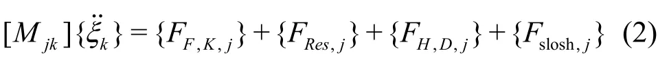
where [Mjk]is the mass matrix of the ship, and {FF,K,j}and {FRes,j}are the Froude-Krylov force and restoring force, respectively. In the traditional linear equation of motion, a constant restoring coefficient and a linear Froude-Krylov force are applied under the assumption that the ship motion and wave amplitude are small.{FH,D,j}represents the hydrodynamic force attributed to the radiation and diffraction waves of a ship, except Froude-Krylov and restoring force. {Fslosh,j}represents the internal sloshing-induced forces.
1.2Analysis of ship motion
The adoption of the potential theory is the typical approach for ship motion analysis. Under the assumption of incompressible, inviscid fluid with irrotational motion, the velocity potential,φ, satisfying the following boundary value problem can be introduced:
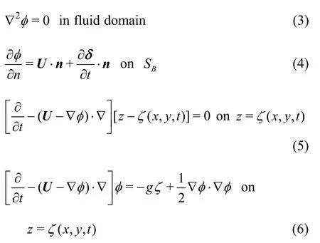
whereSBrepresents the instantaneous wetted body surface, andζandgrefer to wave elevation and gravity constant, respectively. The boundary value problem can be linearized by adopting small amplitude wave assumption(A/λ=ε≪1)and by decomposing the total velocity potential and wave elevation as follows:
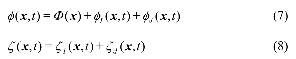
whereΦindicates the basis potential, and its order isO(1).φIandζIdenote the incident wave potential and elevation, respectively. Similarly,φdandζdrepresent the disturbed wave potential and elevation, respectively. Both incident and disturbed componentsareO(ε≪1). The basis potential takes uniform flow,−Ux, in the Neumann-Kelvin linearization, and the double-body flow potential in the double-body linearizaion. The linearized boundary conditions take the following forms:
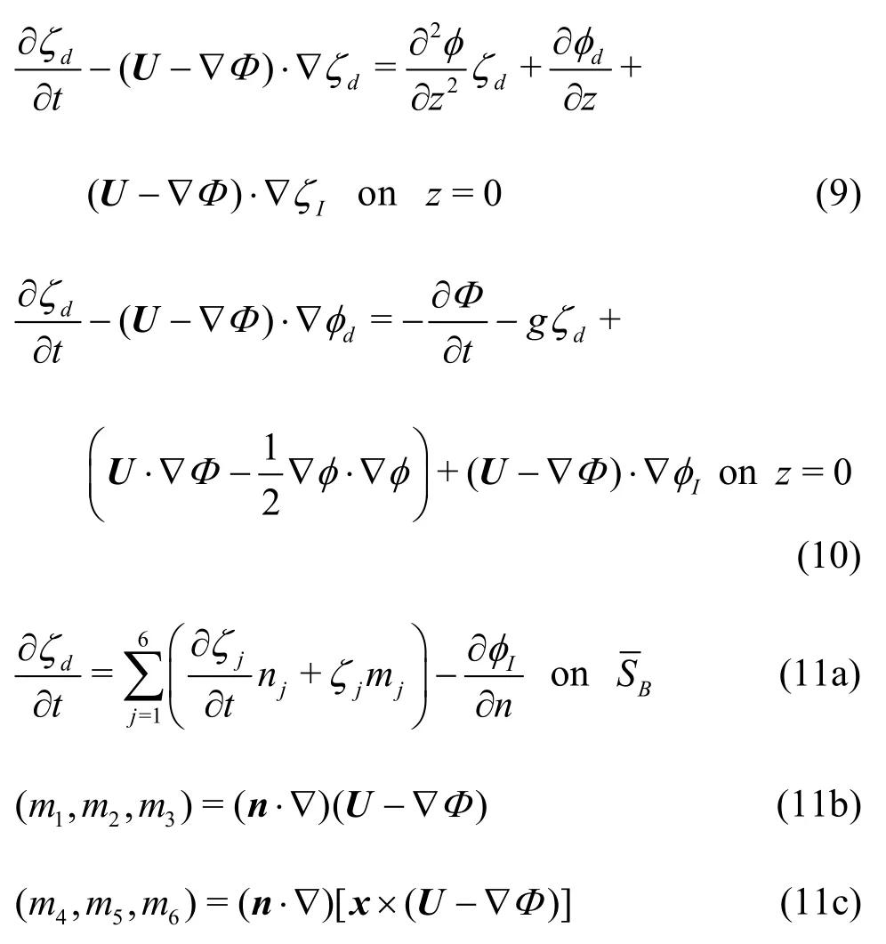
whereis the mean body surface, andmjrepresents them-term, which includes the effects of interactions between the steady and unsteady solutions.
The linearized pressure can be obtained using the velocity potential, which is calculated by solving the linearized boundary value problem.
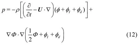
Further, the Froude-Krylov force and hydrodynamic force can be obtained by integrating the linearized pressure on the mean body surface as follows:
1.3Analysis of sloshing flow
In the present study, the sloshing flow in inner tanks was solved using the linear-based Rankine panel method. Because linear-based method is used, there are some limitations in its application. There are two main effects of these limitations. The first is change of dispersion relation. The dispersion relation of nonlinear theory differs from that of linear theory, therefore, there will be some shift of resonance frequencies of sloshing flow. The second is nonlinear increase of sloshing-induced force and moments because of violent sloshing flows such as overturning waves, traveling waves, jet flows which could not be generated using linear based scheme. Although it is impossible to generate severely violent sloshing flow in the inner tanks when using this method, linear sloshing-induced force and moment were used in most of the recently conducted works, and these works concluded that linear sloshing computation may be sufficient for coupling with ship motion. Therefore, sloshing-induced force and moments were calculated using the linear calculation scheme in this study.
To solve the sloshing flow in inner tanks, a similar boundary value problem applied for ship motion analysis can be adopted. However, in this scheme, the terms related to forward speed and incident wave should be excluded because the relative velocity between tank and liquid is zero and because there is no incident wave in the inner tank. Then, the linearized boundary conditions can be written as follows:
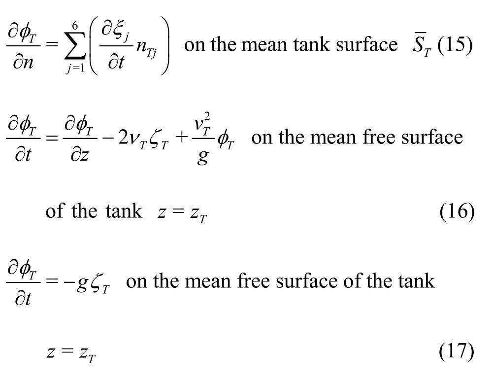
whereφTandζTrepresent the velocity potential and wave elevation, respectively, in the inner tank, andnTrepresents the normal vectors for the inner tank. In the potential theory, the linear solution of sloshing can be divergent or unrealistically large when the excitation frequency is close to the resonance frequency of the inner tank. To make the solution more realistic, the artificial damping coefficient,νT, was applied to the free-surface boundary condition. In the present study,the value ofνTwas 0.05. Kim et al.[7]checked the effect ofνTon motion responses. WhenνTwas 0.05, realistic sloshing flow was generated and motion responses were well agreed with experimental data. Because the present study is based on the research of Kim et al.[7], the same value was used in this study.
The total pressure on the tank surface can be obtained by using velocity potential and Bernoulli’s equation.

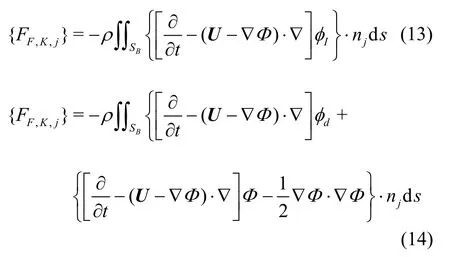
Taking the tank motions into account, the linearized pressure on the mean tank surface can be derived as follows

whereδ(=ξT+ξT×x) denotes motion displacement at an arbitrary position. The second term in Eq.(19) is related to ship motion, and it corrects the vertical motion. The linearized sloshing force and moment can be obtained by integrating the pressure on the tank surface.

Note that this sloshing force includes the inertial force of the inner tank; therefore, the liquid mass of the inner tank is not included in the mass matrix shown in Eq.(1).
1.4Numerical implementation
To solve the prescribed linear boundary value problems, Green’s second identity was applied by discretizing the boundary surface. Fluid boundaries, including the boundaries with the body surface, free surface around the body, tank surface, and free surface inside the tank, were discretized into flat square panels. The Rankine source (G=1/r), which only satisfies the Laplace equation, was applied to these discretized surfaces, and the integral equation was expressed as follows

In the present study, the velocity potential, wave elevation, and normal flux along the fluid boundary were approximated using the B-spline basis function.
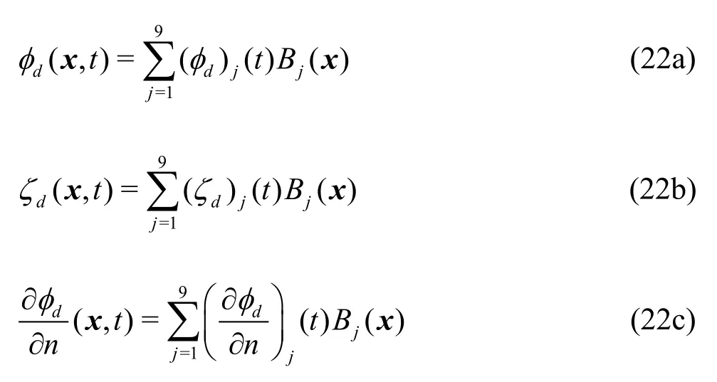
whereBj(x)is aB-spline basis function, and (φd)j(t),(ζd)j(t) and (∂φd/∂n)j(t)denote the coefficients of velocity potential, wave elevation, and the normal flux, respectively, at thej-thdiscretized boundary panel. By substituting Eq.(22) into Eq.(21) and using the boundary value problems described above, a matrix equation with unknown coefficients can be assembled. By solving the matrix equation, the normal flux of velocity potential on the free surface and the velocity potential on the body surface can be obtained. The wave elevation and velocity potential on the free surface can then be obtained by the time integration of the boundary conditions of the free surface.
For the time integration of the boundary conditions of the free surface, a mixed explicit-implicit scheme was used. The kinematic free-surface boundary condition was solved explicitly to obtain the disturbed wave elevation on the free surface, while the dynamic free surface boundary condition was solved implicitly to predict the velocity potential on the free surface in the next time step. These procedures were performed as follows:
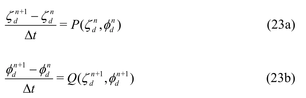
wherePandQare the forcing functions containing all other terms under the free surface boundary condition. In addition, the equation of motion was solved by applying a multi-step time integration method. The 4th-order prediction-correction method was used. In the present study, Rankine panel method was adopted; therefore, panels should be distributed on body surface and free-surface. In the case of free-surface, freesurface is normally truncated, because panels are only
distributed on finite area. So we have to pay attention to radiation condition at truncated free surface. The radiation condition was satisfied by adopting the concept of an artificial wave-absorbing zone. This zone was distributed around the truncated boundary of the free surface, and the kinematic free surface boundary condition was modified to include the artificial damping mechanism, as follows
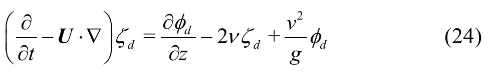
wherevdenotes the damping strength and it has quadratic variation over damping zone. It is expressed as a quadratic term by using the distance between the starting point of the damping zone and the free surface edge, and therefore, the damping strength gradually increased in the outgoing direction.
In the time-domain approach, there are no restoring forces for the surge, sway, or yaw modes, and hence, a soft-spring is widely used to restrict the divergence of the numerical solution. In the present study, the soft-spring system was applied also. Linear dampings were applied for surge, sway, roll, and yaw motions. The strengths of the soft spring and damping were defined as follows:
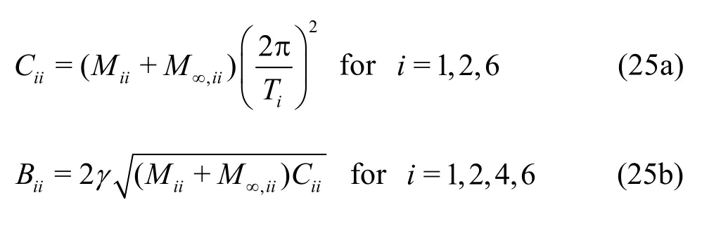
whereM∞is the infinite-frequency added mass, andTiis the soft spring period.γis the damping ratio, and it should be assigned properly. Details of the numerical implementations are found in the papers of Kim et al.[37], Kim et al.[31], and Seo[38].
1.5Prediction of added resistance
In the present study, the near-field method was applied to calculate added resistance. By using Bernoulli’s equation and Taylor’s series expansion, the second-order pressure on the mean body surface was obtained, and the second-order force was obtained by integrating the second-order pressure. Added resistance was obtained by averaging the longitudinal component of the second-order force signal. The secondorder force can be formulated as follows


whereWLandrepresent the waterline and the wetted surface of the mean body, respectively,n1andn2are the first- and second-order normal vectors, which are expressed as follows:
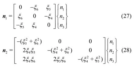
In this study, two types of flow were considered: the external flow around the body, and the internal flow, that is, the sloshing flow in the inner tanks. The second-order force due to the external flow was calculated by directly using Eq.(26), while the terms relatedto forward speed and incident wave component were excluded from the second-order force due to internal flow.
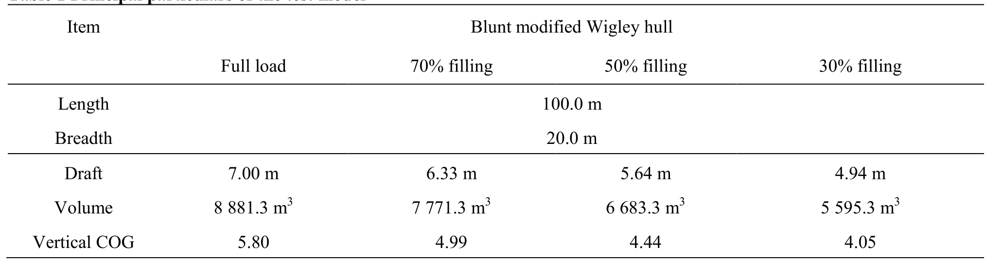
Table 1 Principal particulars of the test model
Note that only a linear solution is needed for computing added resistance because the mean value of second-order solution becomes zero; therefore, there is no need to solve a complete second-order boundary value problem. Details of this formula are presented in the papers of Joncquez[29]and Seo et al.[33,39].
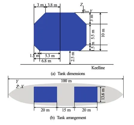
Fig.2 (Color online) Configuration of inner tanks
2. Numerical results
2.1Test model
The model considered in this study is a blunt modified Wigley hull[36]. The main details of the test model with respect to the filling ratios are summarized in Table 1. The main object of this study is to examine the effect of sloshing flow on ship motion and added resistance with respect to the tank filling ratio; therefore, a simple and mathematical model that is easy to handle was chosen as the test model.
Figure 2 shows the configuration of inner tanks. The two tanks are identical, with dimensions of 20.0 m (length)×13.6 m (breadth)×10.0 m (height). The arrangement of these two tanks is symmetry for midship section. An example of solution panel is shown in Fig.3. The number of total panels varies depending on the body shape and wave length, and approximately 6 000 panels were applied on the free surface and body surface for a half domain. In the case of the tank surface, approximately 2 000 panels were used for a half domain. The free surface domain is about five times the incident wavelength.
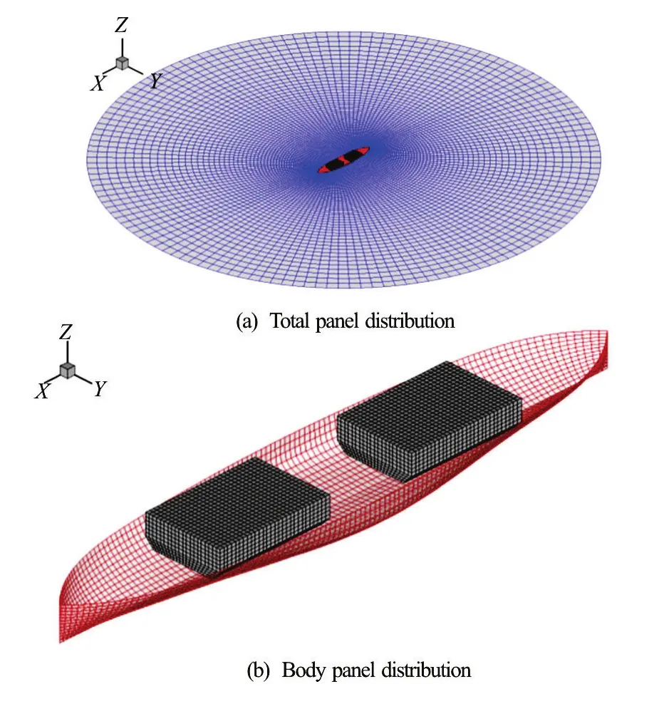
Fig.3 (Color online) Example of the solution panel
2.2Validation of motion and added resistance: Without the inner tank
The present computation starts from the validation of the motion response and added resistances without inner tank. The computed motion responses and added resistances of test model were compared with the experimental data of Kashiwagi[36]. The ship motion response is closely related to added resistance, in particular, to the radiation component of added resistance. Therefore, the exact calculation of the ship motion response is important for accurately predictingthe added resistance. Validation of the motion response and added resistance is described in this section.
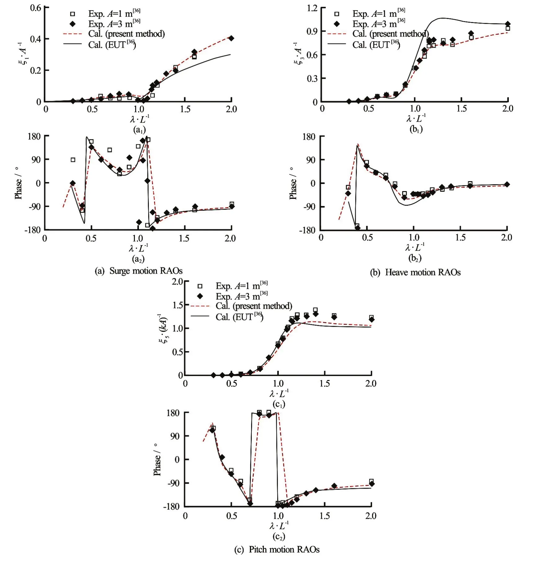
Fig.4 (Color online) Wave induced surge, heave, and pitch motions:Fr=0.2,β=180o
Figure 4 shows the surge, heave, and pitch motion RAOs of the blunt modified Wigley model atFr=0.2. In these figures, red broken lines represent the results of the present method, and black lines show the numerical results of Kashiwagi[36]obtained using the enhanced unified theory (EUT). As shown in these figures, the results of the present method are closer to the experimental data than the EUT results. The overall tendencies of the motion responses computed by the present method are similar to those of the experimental data, however, small discrepancies are seen, especially in pitch motion. Pitch motion calculated by the present method is underestimated, compared with the experimental data. Figure 5 shows the added resistance on the blunt modified Wigley model atFr=0.2. As shown in this figure, the overall values calculatedby the present method are slightly underestimated as compared with the experimental data. This discrepancy is attributed to the low pitch motion responses.

Fig.5 (Color online) Added resistance on the blunt modified Wigley model:Fr=0.2,β=180o
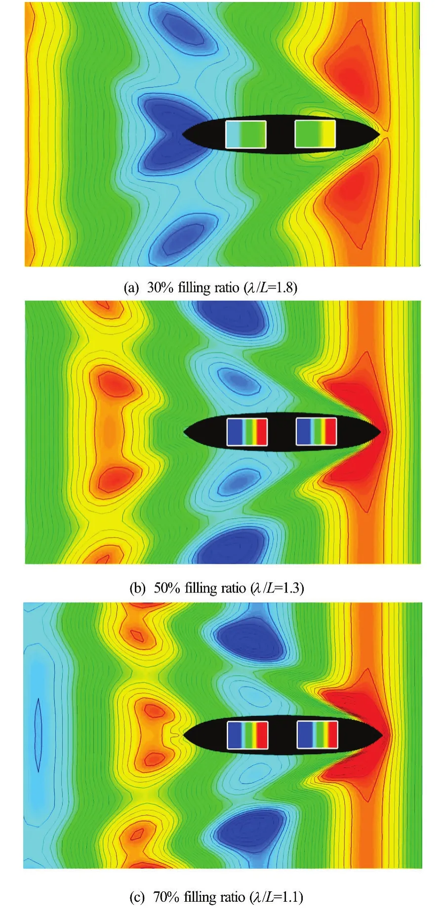
Fig.6 (Color online) Wave patterns at the resonance period of the inner tank:Fr=0.2,β=180o, surge fixed
2.3Coupled problems: With inner tanks
To observe the effect of the sloshing flow in inner tanks on the ship motion and added resistance, different filling ratios of inner tanks−30%, 50%, and 70%−were considered. Draft and displacement volume were also changed according to the tank filling ratio, as summarized in Table 1. The resonance periods of the inner tank are 7.64 s (λ/L=1.71)at 30% filling ratio, 6.25 s(λ/L=1.21)at 50% filling ratio, and 5.66 s(λ/L=1.08)at 70% filling ratio.

Fig.7 (Color online) Wave-induced surge, heave, and pitch motions:Fr=0.2,β=180o, filling ratio is 30%
Figure 6 shows the instantaneous wave contours around the ship model and the free surface contours inside the tanks with different tank filling ratios. The incident wave period in each case was almost the same as the resonance period of the inner tanks. In the case of 50% and 70% filling ratio, violent sloshing flow was generated; however, the sloshing flow in inner tanks was quite small at the tank filling ratio of 30%. This was so because the ship motion was large enough to generate violent sloshing flow at 50% and 70% filling ratio, while it was too small to generate severe sloshing flow in the inner tank at 30% filling ratio.

Fig.8 (Color online) Wave-induced surge, heave, and pitch motions:Fr=0.2,β=180o, filling ratio is 50%
Figures 7, 8 and 9 show the surge, heave, and pitch motion RAOs at 30%, 50%, and 70% filling ratios, respectively. Each figure shows three types of computation results: the computation results without inner tank (black solid lines, the same as those for the present method shown in Fig.4), the computation results with inner tanks and for the free surge case (red broken lines), and the computation results with iner tanks and for the fixed surge case (blue dash-and-dot lines). As seen from these figures, there are some discrepancies among the numerical results. In the case of fixed surge motion, the heave and pitch motions decrease sharply near the resonance period of the inner tank unlike in the case without the tank. In the case of free surge motion, the heave and pitch motions are similar to those in the case without the tank, while the surge motion generally increases over the whole wave range.

Fig.9 (Color online) Wave-induced surge, heave, and pitch motions:Fr=0.2,β=180o, filling ratio is 70%
Figures 10, 11 show the time-varying free-surface profiles at the resonance periods of the inner tanks for the filling ratio of 50%. Figure 10 shows the fixed surge case, and Fig.11 represents the free surge case. As shown in these figures, the sloshing flow in the fixed surge case is much severe than that in the free surge case. As mentioned before, this is because the coupling effect of surge and pitch motion changes the overall tendencies and suppresses the sloshing flow in the inner tanks.
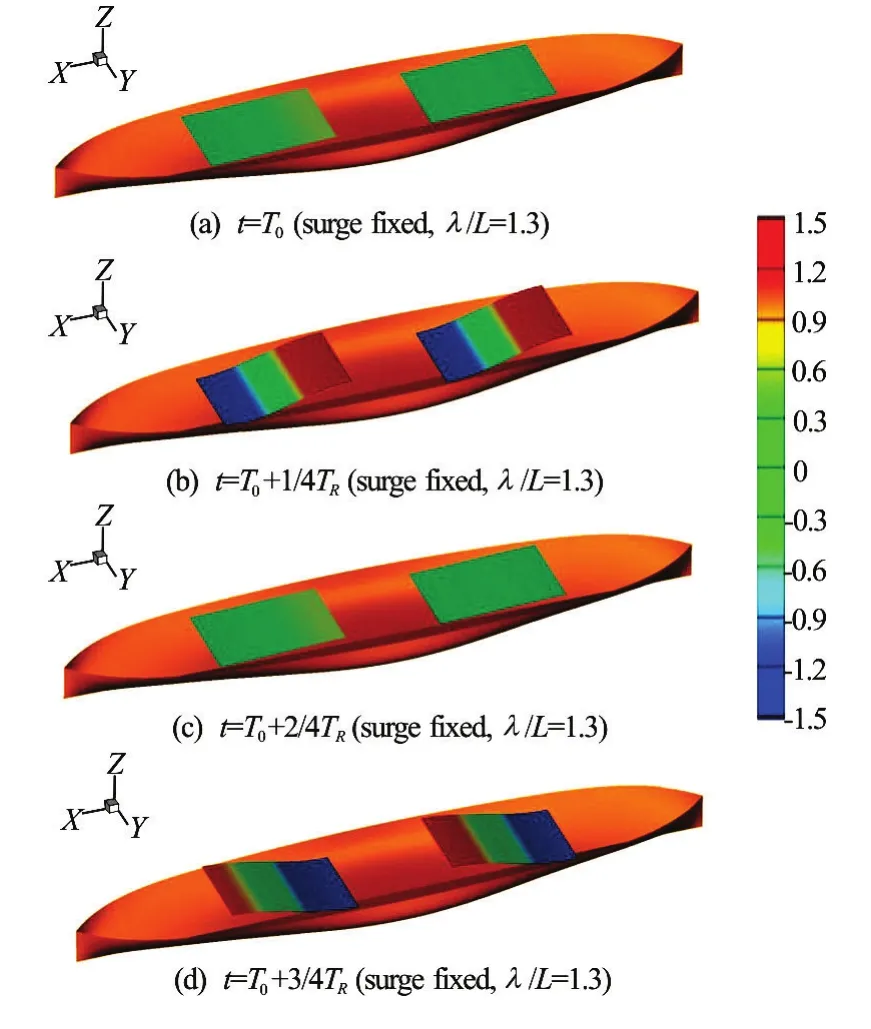
Fig.10 (Color online) Sloshing flow at the resonance period of the inner tank:Fr=0.2,β=180o, filling ratio is 50%, surge fixed

Fig.11 (Color online) Sloshing flow at the resonance period of the inner tank:Fr=0.2,β=180o, filling ratio is 50%, surge free
To confirm the causes of this phenomenon, the sloshing forces and moments in the inner tanks were checked at 50% filling, as shown in Fig.12. The Red broken lines indicate the sloshing force and moment under free surge motion, and blue dash-and-dot lines indicate the sloshing force and moment for fixed surge motion. Froude-Krylov force and moment are also plotted as black solid lines in these figures for reference. As shown in these figures, the peak values of the surge force and pitch moment of the free surge case are much smaller than those of the fixed surge case.
In addition, the peak period of surge force and pitch moment of the free surge case is different from the resonance period of the inner tank. The resonance period of the inner tank at 50% filling ratio is 6.25 s (λ/L=1.26), while the peak period of the surge force and pitch moment of the free surge case is 5.51 s (λ/L=1.05). This is because the coupling effect of surge and pitch motions changes the overall tank excitation motion, and consequently, suppresses the sloshing flow inside tanks.
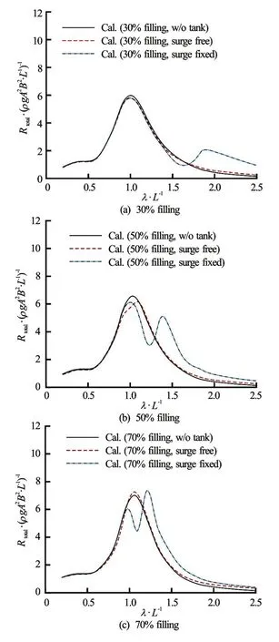
Fig.13 (Color online) Added resistance on the blunt modified Wigley model:Fr=0.2,β=180o
Figure 13 shows the added resistance on the blunt modified Wigley model at 30%, 50% and 70% filling ratios. This figure also shows three types of computation results: those without the inner tank (black lines), those with the tank and with free surge (red broken lines), and those with the inner tank and with fixed surge (blue dash-and-dot lines). In the free surge case, the added resistance is almost the same as that in the case without the tank. This is because the heave and pitch motion responses in both cases are similar.
In the case of fixed surge motion, added resistance shows larger discrepancies than in the other cases. When the wavelength is smaller than the resonance point of the inner tank, the added resistance is almost the same as that in the other cases because the sloshing flow is small in this region. While, near the resonance point of the inner tank, the added resistance is significantly less than that in the other cases, and then it increases again when incident wave becomes longer than the resonance point of the inner tank. To confirm the cause of this phenomenon, the relative motion, which is closely related to added resistance, was analyzed. The relative motion is defined as follows
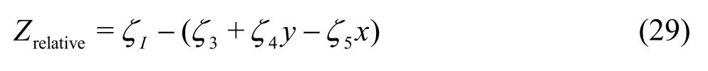
whereζIis incident wave elevation, andξ3,ξ4andξ5denote heave, roll, and pitch motions, respectively. In other words, relative motion indicates the wetted depth of an arbitrary point (x,y). Figure 14 shows the relative motion at the forward perpendicular (FP) with respect to wavelength.
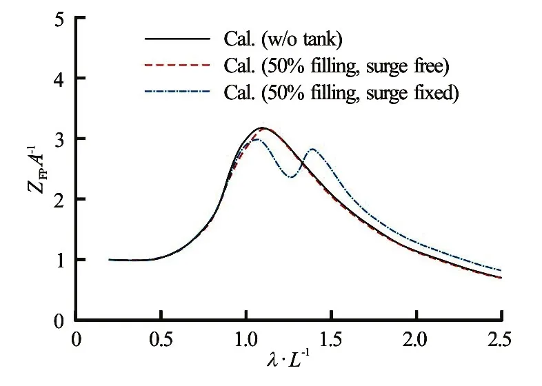
Fig.14 (Color online) Relative motion at FP:Fr=0.2,β=180o, filling ratio is 50%
The relative motion in the free surge case is almost the same as that in the case without the tank, while that in the fixed surge case shows different tendency when the incident wavelength is larger than the resonance point of the inner tank. Near the resonance point of the inner tank, the relative motion is smaller than that in the other cases, while it is larger than in the other cases when the incident wavelength is larger than the resonance point of the inner tank. This tendency is exactly the same as that of the added resistance. In Eq.(26), the first term is the waterline integration of the square of relative motion, and this is the main contribution of added resistance. Therefore, added resistance shows a tendency similar to that of the relative motion. The results obtained thus far indicate that the sloshing flow in the fixed surge case is relatively larger than that in the other cases, and that this violent sloshing flow causes changes in heave and pitch motions, resulting in changes in relative motion and added resistance.
Next, the contributions of the external flow (flow near the body, hull component) and internal flow (sloshing flow, inner tank component) to the added resis-tance were examined. As mentioned above, Eq.(26) can be used not only for the external flow, but also for the internal flow by excluding ship speed and incident wave components. Figure 15 shows the contribution of each flow to added resistance. As shown in this figure, most of the added resistance can be attributed to the hull component, and the inner tank component attributed to sloshing flow is small enough to be neglected. This means that added resistance is mostly influenced by the coupled effects of sloshing motion, while the hydrodynamic pressure on the tank wall does not directly contribute much to the added resistance.
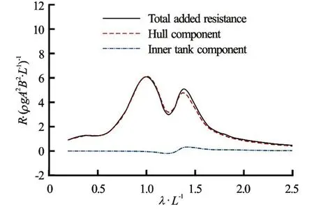
Fig.15 (Color online) Components of added resistance:Fr= 0.2,β=180o, filling ratio is 50%, surge fixed
3. Conclusions
In this study, the responses of motion of a ship moving through waves, coupled with sloshing-induced internal flow, were analyzed. The effect of sloshing flow on added resistance was observed by using a time-domain Rankine panel method. The test model was a blunt modified Wigley hull with two inner tanks. The numerical results obtained without the inner tanks were compared with the existing experimental data for validation, and then the effects of filling ratio inside inner tanks were examined. The following conclusions were drawn:
(1) The ship motion responses affect the sloshing flow in the inner tank, and the severity of the sloshing flow changes depending on surge motion. In the case of fixed surge motion, the heave and pitch motions show larger discrepancy than in the case without the tank near the resonance point of the inner tank. In the case of free surge motion, the heave and pitch motions are similar to those in the case without the tank, while the surge motion generally increases. It is considered that the coupling effect of surge and pitch motions changed the overall tank excitation motion, consequently suppressing the sloshing flow in the inner tank. Therefore, it is necessary to accurately consider the coupling effect among motion components.
(2) The added resistance in the case of free surge motion is almost the same as that in the case without the tank, while that in the case of fixed surge motion shows different tendency compared towith the other cases. Near the resonance point of the inner tank, the added resistance decreases more significantly than in the other cases; and then increases when the incident wavelength exceeds the resonance point of the inner tank. Therefore, when the liquid cargo ship operates in a real sea, it is necessary to consider the change in the added resistance for predicting ship speed loss or change in engine power.
(3) Comparison of the components of added resistance shows that the hull component attributed to the external flow is much larger than the inner tank component attributed to sloshing flow. This means that changes in added resistance is mainly caused by changes in the ship motion responses, and that the component of added resistance attributed to the sloshing flow in the inner tank of the ship can be ignored. Therefore, to calculate the added resistance accurately, it is important to accurately determine the coupled motion with sloshing flow.
Acknowledgement
This study was partly funded by the Ministry of Trade, Industry and Energy (MOTIE), Korea, under Industrial Technology Innovation Program (Grant No. 10062881), “Technology Development to Improve Added Resistance and Ship Operational Efficiency for Hull Form Design,” and the NICOP project (Grant No. N62909-15-1-2020, supported by Office of Naval Research Global. It was also partly funded by the LRF*–Funded Research Center at Seoul National University. All the supports are greatly appreciated. The administrative support of RIMSE and ERI are also acknowledged (* Lloyd’s Register Foundation (LRF): a UK-registered charity and sole shareholder of Lloyd’s Register Group Ltd., that invests in science, engineering, and technology for public benefit worldwide).
[1] Kim Y. A numerical study on sloshing flows coupled with ship motion-the anti-rolling tank problem [J].Journal of Ship Research, 2002, 46(1): 52-62.
[2] Rognebakke O. F., Faltinsen O. M. Coupling of sloshing and ship motions [J].Journal of Ship Research, 2003, 47(3): 208-221.
[3] Malenica S., Zalar M., Chen X. B. Dynamic coupling of seakeeping and sloshing [C].The Thirteenth International Offshore and Polar Engineering Conference. Hawaii, USA, 2003.
[4] Newman J. N. Wave effects on vessels with internal tanks [C].Proceedings of the 20th Workshop on Water Waves and Floating Bodies. Spitsbergen, Norway, 2005.
[5] Nam B. W., Kim Y., Kim D. W. et al. Experimental and numerical studies on ship motion responses coupled withsloshing in waves [J].Journal of Ship Research, 2009, 53(2): 68-82.
[6] Kawabe H., Park J., Ha M. The second order wave exciting force on a floating ship considering tank liquid dynamic effect [C].Proceedings of the Ninth ISOPE Pacific/ Asia Offshore Mechanics Symposium. Busan, Korea, 2010.
[7] Kim T., Kim Y., Gou Y. Motion responses of a liquefied natural gas-floating production storage and offloading unit coupled with sloshing excitation [J].The IES Journal Part A: Civil and Structural Engineering, 2011, 4(3): 157-166.
[8] Lee S. J., Kim M. H., Kim J. W. et al. The effect of LNG-tank sloshing loads on the motions of LNG carriers [J].Ocean Engineering, 2007, 34(1): 10-20.
[9] Kim B., Shin Y. S. Coupled seakeeping with liquid sloshing in ship tanks [C].ASME 2008 27th International Conference on Offshore Mechanics and Arctic Engineering. Estoril, Portugal, 2008.
[10] Cho S. K. A study on the motion behavior of side-by-side moored two floaters including sloshing effects [D]. Doctoral Thesis, Seoul, Korea: Seoul National University, 2012.
[11] Gerritsma J., Beukelman W. Analysis of the resistance increase in waves of a fast cargo ship [J].International Shipbuilding Progress, 1972, 19(217): 285-293.
[12] Storm-Tejsen J., Yeh H. Y. H., Moran D. D. Added resistance in waves [J].Transactions of the Society of Naval Architects and Marine Engineers, 1972, 81: 109-143.
[13] Fujii H., Takahashi T. Experimental study on the resistance increase of a ship in regular oblique waves [J].Proceeding of the 14th International Towing Tank Conference. Ottawa, Canada, 1975, 351-360.
[14] Nakamura S., Naito S. Propulsive performance of a containership in waves [J].Naval Architecture and Ocean Engineering, 1977, 15: 24-48.
[15] Journee J. M. J. Experiments and calculations on four Wigley hull forms [R]. Delft University of Technology Photocopie du Report 909, Delft, The Netherlands: Delft University of Technology, 1992.
[16] Guo B. J., Steen S. Evaluation of added resistance of KVLCC2 in short waves [J].Journal of Hydrodynamics, 2011, 23(6): 709-722.
[17] Sadat-Hosseini H., Wu P., Carrica P. M. et al. CFD verification and validation of added resistance and motions of KVLCC2 with fixed and free surge in short and long head waves [J].Ocean Engineering, 2013, 59(1): 240-273.
[18] Kuroda M., Tsujimoto M., Sasaki N. et al. Study on the bow shapes above the waterline in view of the powering and greenhouse gas emission in actual seas [J].Journal of Engineering for the Maritime Environment, 2011, 226(1): 23-35.
[19] Lee J. H., Seo M. G., Park D. M. et al. Study on the effects of hull form on added resistance [C].The 12th International Symposium on Practical Design of Ships and Other Floating Structures. Changwon, Korea, 2013.
[20] Park D. M., Seo M. G., Lee J. H. et al. Systematic experimental and numerical analyses on added resistance in waves [J].Journal of the Society of Naval Achitects of Korea, 2014, 51(6): 459-479.
[21] Park D. M., Lee J. H., Kim Y. Uncertainty analysis for added resistance experiment of KVLCC2 ship [J].Ocean Engineering, 2015, 95: 143-156.
[22] Maruo H. The drift of a body floating on waves [J].Journal of Ship Research, 1960, 4: 1-5.
[23] Newman J. N. The drift force and moment on ships in waves [J].Journal of Ship Research, 1965, 11(1): 51-60.
[24] Salvesen N. Added resistance of ship in waves [J].Journal of Hydronautics, 1976, 12(1): 24-34.
[25] Kashiwagi M., Takehiro I., Takuma S. Effect of forward speed of a ship on added resistance in waves [C].The 19th International Offshore and Polar Engineering Conference. Osaka, Japan, 2009.
[26] Faltinsen O. M., Minsaas K. J., Liapis N. et al. Prediction of resistance and propulsion of a ship in a seaway [C].Proceedings of 13th Symposium on Naval Hydrodynamics, Tokyo, Japan, 1980, 818-825.
[27] Ye H. K., Hsiung C. C. Computation of added wave resistance of a restrained floating body in the time-domain [J].International Shipbuilding Progress, 1997, 44(437): 27-57.
[28] Bunnik T. H. J. Seakeeping calculations for ships, taking into account the non-linear steady waves [D]. Doctoral Thesis, Delft, The Netherlands: Delft University of Technology, 1999.
[29] Joncquez S. A. G. Second-order forces and moments acting on ships in waves [D]. Doctoral Thesis, Copenhagen, Denmark: Technical University of Denmark, 2009.
[30] Kim K. H., Kim Y. Numerical study on added resistance of ships by using a time-domain Rankine panel method [J].Ocean Engineering, 2011, 38(13): 1357-1367.
[31] Kim K. H., Seo M. G., Kim Y. Numerical Analysis on Added Resistance of Ships [J].International Journal of Offshore and Polar Engineering, 2012, 22(1): 21-29.
[32] Jeong K. L. Numerical simulation of the flow around floating bodies in regular head waves using a three-dimensional rectilinear grid system [D]. Doctoral Thesis, Inchon, Korea: Inha University, 2013.
[33] Seo M. G., Yang K. K., Park D. M. et al. Numerical analysis of added resistance on ships in short waves [J].Ocean Engineering, 2014, 87(9): 97-110.
[34] Yang K. K., Seo M. G., Kim Y. Analysis of added resistance in short wave [J].Journal of the Society of Naval Architects of Korea, 2015, 52(4): 338-345.
[35] Yang K. K. Analysis of added resistance on ships in waves based on Cartesian-grid method [D]. Doctoral Thesis, Seoul, Korea: Seoul National University, 2015.
[36] Kashiwagi M. Hydrodynamic study on added resistance using unsteady wave analysis [J].Journal of Ship Research, 2013, 57(4): 220-240.
[37] Kim Y., Kim K. H., Kim J. H. et al. Time-domain analysis of nonlinear motion responses and structural loads on ships and offshore structures: Development of WISH programms [J].International Journal of Naval Architecture and Ocean Engineering, 2011, 3(1): 37-52.
[38] Seo M. G. Study on prediction method for ship operation performance in waves [D]. Doctoral Thesis, Seoul, Korea: Seoul National University, 2016.
[39] Seo M. G., Park D. M., Yang K. K. et al. Comparative study on computation of ship added resistance in waves [J].Ocean Engineering, 2013, 73(6): 1-15.
* Biography:Min-Guk Seo (1985-), Male, Ph. D., Researcher
Corresponging author:Yonghwan Kim, E-mail:yhwankim@snu.ac.kr
杂志排行

水动力学研究与进展 B辑的其它文章
- Large eddy simulation of free-surface flows*
- Large eddy simulation of turbulent attached cavitating flow with special emphasis on large scale structures of the hydrofoil wake and turbulence-cavitation interactions*
- Assessment of the predictive capability of RANS models in simulating meandering open channel flows*
- The lubrication performance of water lubricated bearing with consideration of wall slip and inertial force*
- Ice accumulation and thickness distribution before inverted siphon*
- Lattice Boltzmann simulations of oscillating-grid turbulence*