Flow choking over weir flow slit-type flip buckets*
2015-12-01MAFei马飞XUZhun徐准WUJianhua吴建华CollegeofWaterConservancyandHydropowerEngineeringHohaiUniversityNanjing210098Chinamailmafei921163com
MA Fei (马飞), XU Zhun (徐准), WU Jian-hua (吴建华)College of Water Conservancy and Hydropower Engineering, Hohai University, Nanjing 210098, China,E-mail: mafei921@163.com
Flow choking over weir flow slit-type flip buckets*
MA Fei (马飞), XU Zhun (徐准), WU Jian-hua (吴建华)
College of Water Conservancy and Hydropower Engineering, Hohai University, Nanjing 210098, China,E-mail: mafei921@163.com
(Received August 19, 2015, Revised November 20, 2015)
The flow choking may occur for weir flow slit-type flip buckets under common operation conditions. An estimation method is developed through introducing a comprehensive coefficient to determine the approach flow Froude number for the flow choking to occur in those flip buckets. The error of the present method relative to the experimental data is less than 5%. The results show that, the Froude number for the flow choking to occur is related to the contraction ratio and the contraction angle of the flip buckets. When the flow choking occurs, the upper jet trajectory decreases and the lower one is almost not affected, and the dynamic pressures on the bottom and the sidewalls increase due to the flow profile rising on the flip buckets.
flow choking, jet trajectory, dynamic pressure, slit-type flip bucket, weir flow
Introduction0F
Flip buckets are widely used to discharge flood for their simple structures and the economy considerations[1]. Recently, the research and development of the flip buckets, including the circular-shaped[2-4]or triangular-shaped flip buckets[5-7], the slit-type or multiple slit-type flip buckets[8,9], the beveled flip buckets[10]and the deflectors[11-13], is very active with related hydraulics studies. For particular applications, the flip buckets usually have a local channel portion with a negative bottom slope or a contraction to deflect the jet. This may lead to an undesirable phenomenon, i.e.,the so-called flow choking. The flow choking means that the flow transfers from the supercritical regime to the subcritical regime, and a roller occurs locally on the flip bucket. Once the flow is choked, the jet collapses close to the toe of the bucket, which may cause scour[14].
The flow choking in the flip bucket of a spillway or the discharge tunnel of a hydropower station is among the classic topics in hydraulics. It has received attention in recent years. In the operations of release works, the risk of flow choking occurrence needs to be examined if the flow Froude number is too small. Heller et al.[15]demonstrated that the flow choking over the spillway buckets shows different characteristics in rising and falling discharge regimes. They also presented theoretical and empirical expressions for predicting the flow choking over the circular-shaped flip bucket. Savic et al.[16], Lucas et al.[11], and Khatsuria[17]gave empirical expressions for estimating the flow choking for different types of flip buckets with the same width.
A slit-type flip bucket consists of contraction sidewalls, and the flows over the bucket may become submerged and then be locally subcritical. Wu et al.[9]developed multiple slit-type flip buckets, and observed the process of flow choking, including the appearance, the formation, the development and the disappearance. They pointed out that those multiple slits can decrease the choking Froude number. Compared with the conventional slit-type flip bucket, this type can avoid the flow choking to some extent. More recently, Wu et al.[18]investigated the effects of the outlet width, the contraction angle, and the gate opening on the flow choking Froude numbers for orifice flow slit-type flip buckets, and presented the Froude num-bers for the appearance and the disappearance of the flow choking.
The approach flow Froude number increases with the increase of the water head for an orifice flow, but decreases with the increase of the water head for a weir flow. Therefore, one sees remarkable different characteristics of the flow choking over those two slittype flip buckets. In the weir flow slit-type bucket, the flow choking may occur due to a low approach flow Froude number under common operation conditions. So it is crucial to investigate this type of flow choking. The objectives of this paper are to theoretically predict the flow choking for the weir flow slit-type flip buckets, and to experimentally investigate the effects of flow choking on the bucket hydraulics, such as the jet trajectory, the flow profile and the dynamic pressure distributions.
1. Experimental setup and methodology
The experiments are conducted in the high-speed flow laboratory of Hohai University (HFL-HHU). The experimental setup consists of a feed basin, a crest spillway, and a tailwater channel connected to an underground reservoir and a pump for providing the water recirculation from the underground reservoir to the feed basin. The crest spillway comprises of a WES spillway and a slit-type flip bucket settled at the end of the crest spillway. The crest spillway model is made of plexy-glass.
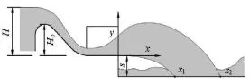
Fig.1 The flow over weir slit-type flip bucket
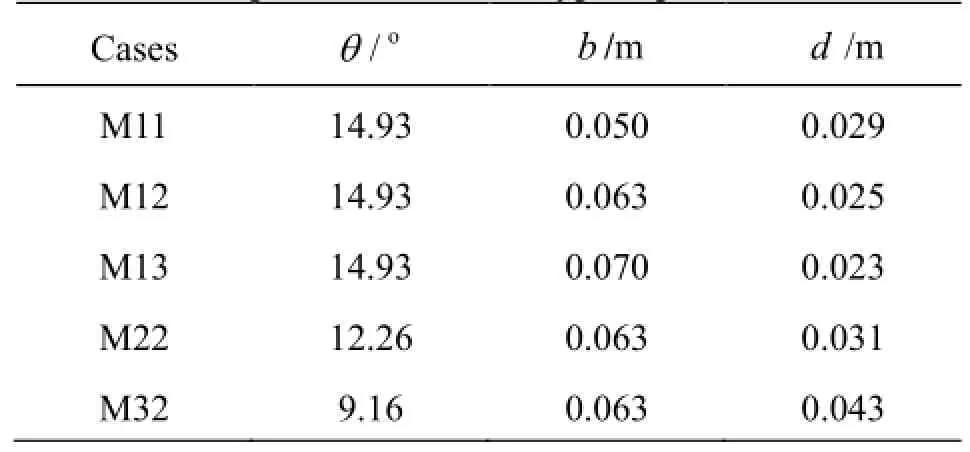
Table 1 Model parameters of slit-type flip bucket
Figure 1 shows the flow over a weir slit-type flip bucket with main definitions of symbols. The origin of the coordinate system (x, y)is at the edge of the flip bucket.S=0.750 m, is the elevation difference between the bucket bottom and the tailwater channel, Ho=0.258 m, is the height from the crest top to the bucket bottom, andH is the operation head for the flip bucket,x1and x2are the impact points of the lower and upper jet trajectories onto the tailwater channel, respectively, determined visually from the river side, by extending the jet trajectories.
Table 1 lists the model parameters of the slit-type flip buckets, the cases M11, M12 and M13 are used to investigate the effect of the outlet widthb , whereas the cases M12, M22 and M32 are for the effect of the contraction angleθ. The channel widthBis kept a constant of 0.163 m.

Fig.2 Layout of dynamic pressure probe
Figure 2 is the layout of dynamic pressure probes for both the bottom (Fig.2(a)) and the sidewall(Fig.2(b)) of the flip bucket. There are eight probes on the bottom center line separated with a distance d(see Table 1). For the eight probes on the sidewall, they are all at x=-l/2, wherelis the length of the flip bucket, and are located at 0.01 m, 0.04 m, 0.07 m, 0.10 m, 0.13 m, 0.16 m, 0.21, and 0.26 m along they direction. In the experiments, the water level for the headH is measured with a point gauge, the discharge Q with a V-notch, the jet trajectory (x1or x2) and the pressure head Hpare measured with rulers.
2. Results and discussions
2.1 Observations of flow choking
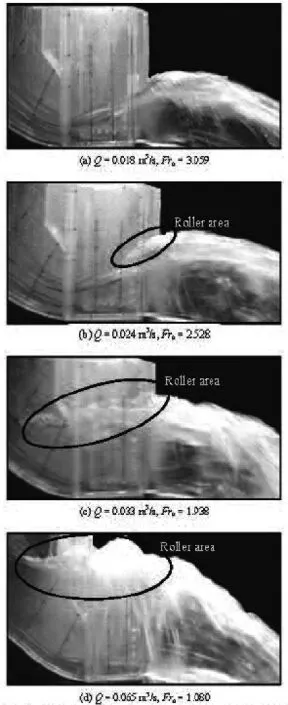
Fig.3 Process of flow choking over weir flow slit-type flip bucket (M12)
Figure 3 shows the flow choking over a weir flow slit-type flip bucket. Under the condition of small discharge, the flow choking does not appear due to the large approach flow Froude number Fro(Fig.3(a)). With the increase of the discharge,Frogradually decreases, and a roller occurs at the end of the bucket,which means the flow is choked (Fig.3(b)). Then, the roller develops toward upstream (Fig.3(c)). When the discharge continues to increase, the roller fully submerges the slit-type flip bucket, and the water overtops from the sidewalls (Fig.3(d)). However, for an orifice flow slit-type flip bucket, the flow choking occurs in cases of small discharge, and may disappear with the increase of the discharge due to different characteristics of the approach flow Froude number, as shown in Fig.4[18]. Therefore, it is necessary to pay attention to the flow choking over the weir flow slittype bucket, especially under conditions of large discharges.
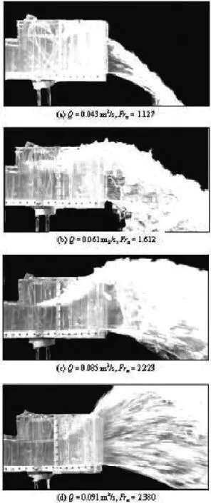
Fig.4 Process of flow choking over orifice flow slit-type flip bucket
2.2 Prediction of flow choking
Figure 5 shows the control volume (CV) of the flow over a weir slit-type flip bucket. For this CV, the momentum equation in x direction is established as follows
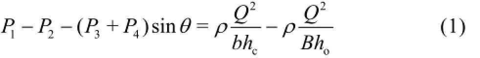
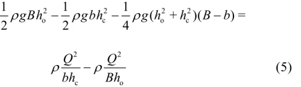
Assuming that all the forces on the CV follow the static pressure distribution, we have:
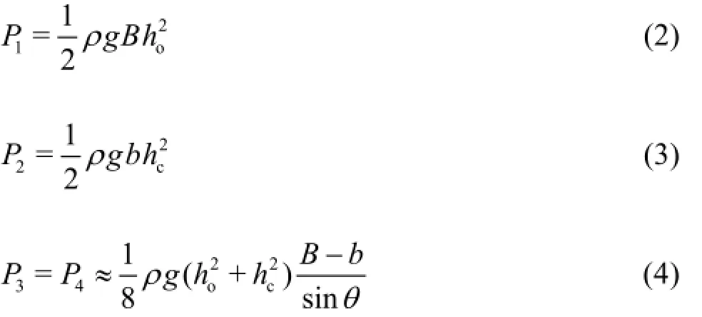
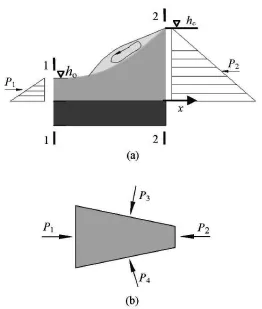
Fig.5 Control volume and forces for predicting choking
Thus, Eq.(1) can be written as
At the Section 2.2, the flow Froude number Fr2is approximately equal to one when a partial hydraulic jump occurs and the sequent depth section is just at the edge of the bucket outlet. Thus, the dischargeQ can be expressed as

By means of the continuity equation, the approach flow Froude number Frofollows the relation

In terms of Eqs.(6) and (7), Eq.(5) may be rewritten for the choking bound as
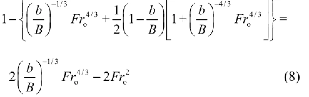
In fact, there are some inaccuracies in the assumptions of the static pressure distribution about P2and P3(or P4), and of Fr2≈1. In order to eliminate those inaccuracies, a comprehensive coefficientm can be introduced in Eq.(8), and then we have

Table 2 shows the values ofmcalculated from the experimental data when the flow choking occurs according to Eq.(9). Figure 6 shows howm is related to the geometric parameters of the slit-type flip bucket. On the basis of those data, the best fit is (R2=0.998)
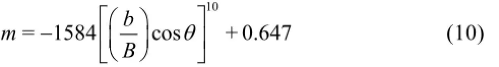
for 0.31<b/ B<0.45, and 9.16o<θ<14.93o. Equations (9) and (10) indicate that, for a weir flow slittype flip bucket, the Froude number Frofor flow choking to occur is directly dominated by the ratio b/ B and the contraction angleθ.

Table 2 Froude numbers of flow choking in different cases

Fig.6 Variation ofm with [b/(Bcosθ)]10
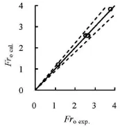
Fig.7 Comparisons between Frocal.and Froexp.
Figure 7 gives comparisons between the calculated (subscriptcal.) and experimental (subscriptexp.) Froude numbers for flow choking to occur. In the figure, the dotted lines give the range of the relative error(Err)of 10 % on the basis of
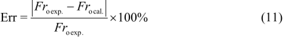
It could be seen that, for Frocal., all relative errors are less than 5.0%. It implies that, Eqs.(9) and (10) are highly accurate in estimating the flow choking over the weir flow slit-type flip bucket.

Fig.8 Variations of x2/Howith Fro
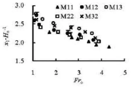
Fig.9 Variations of x1/Howith Fro
2.3 Effects of flow choking
Figures 8 and 9 show the upper and lower jet trajectories, respectively. For each case, the dot with “T”stands for the transition state from without flow choking to with flow choking when Frodecreases orH increases gradually. It can be noticed that, for the upper jet trajectory x2/Ho(Fig.8), in the region of without flow choking (right side of the dot with “T”),the jet trajectory increases with the decrease of Froor the increase ofH , while for the region of with flow choking, the jet trajectory decreases with the decrease of Froor the increase ofHdue to the effects of flow choking. This is an important effect of the flow choking on x2/Ho. On the other hand, the flow choking has almost no effect on the lower jet trajectory, and x1/Homonotonically increases when Frodecreases orH increases for either cases with or without flow choking (Fig.9).
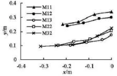
Fig.10 Flow profile on weir flow slit-type flip bucket(H/ Ho=1.81)
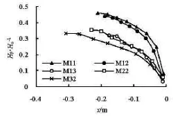
Fig.11 Bottom pressure distributions on weir flow slit-type flip bucket (H/ Ho=1.81)
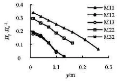
Fig.12 Sidewall vertical pressure distributions on weir flow slittype flip bucket (x=-l/2,H/ Ho=1.81)
Figures 10-12 demonstrate the flow profile, the bottom and sidewall vertical pressure distributions of those flip buckets, respectively, at H/ Ho=1.81. Thepressure distribution is expressed as Hp/Ho, in which Hpis the pressure head.H/ Ho=1.81is selected because the flow regimes are in the state of with flow choking for cases M11 and M12, but not for cases M13, M22 and M32 at this head. Obviously, the flow profiles of the choking states (M11 and M12) are all much higher than those in non-choking states (M13,M22 and M32) (Fig.10), resulting in large bottom and sidewall vertical pressures (Figs.11 and 12).
3. Conclusions
A comprehensive coefficient is introduced in order to correct the inaccuracies resulted from the assumptions of the static pressure distribution about P2and P3(or P4), and of Fr2≈1. With this coefficient, a method is developed to estimate the approach flow Froude number Frowhen the flow choking occurs over the weir flow slit-type flip bucket. With the present method, results are within a relative error of 5%.
The results show that Frofor the flow choking to occur is only dominated by the geometric parameters, including the ratio b/ B and the contraction angleθ. Under the condition of flow choking, the upper jet trajectory decreases, and the lower one is not affected. Meanwhile, the dynamic pressures increase due to the flow profile rising on the bottom and sidewall for the weir flow slit-type flip buckets.
[1] KHATSURIA R. M. Hydraulics of spillways and energy dissipators[M]. New York, USA: Marcel Dekker,2005.
[2] PFISTER M., HAGER W. H. and BOES R. M. Trajectories and air flow features of ski jump generated jets[J]. Journal of Hydraulic Research, 2014, 52(3):336-346.
[3] HELLER V., HAGER W. H. and MINOR H.-E. Closure to “Ski jump hydraulics” by Valentin Heller, Willi H. Hager, and Hans-Erwin Minor[J]. Journal of Hydraulic Engineering, ASCE, 2006, 132(10): 1115-1117.
[4] SCHMOCKER L., PFISTER M. and HAGER W. H. et al. Aeration characteristics of ski jump jets[J]. Journal of Hydraulic Engineering, ASCE, 2008, 134(1): 90-97.
[5] STEINER R., HELLER V. and HAGER W. H. et al. Deflector ski jump hydraulics[J]. Journal of Hydraulic Engineering, ASCE, 2008, 134(5): 562-571.
[6] PFISTER M., HAGER W. H. Deflector-jets affected by preaerated approach flow[J]. Journal of Hydraulic Research, 2012, 50(2): 181-191.
[7] PFISTERf M., HAGER W. H. Deflector-generated jets[J]. Journal of Hydraulic Research, 2009, 47(4):466-475.
[8] WU Jian-hua, MA Fei and YAO Li. Hydraulic characteristics of slit-type energy dissipaters[J]. Journal of Hydrodynamics, 2012, 24(6): 823-828.
[9] WU Jian-hua, YAO Li and MA Fei. Hydraulics of a multiple slit-type energy dissipater[J]. Journal of Hydrodynamics, 2014, 26(1): 86-93.
[10] XUE Hong-cheng, DIAO Ming-jun and YUE Shu-bo et al. Numerical simulation of water-air two-phase jet flow from flip bucket to plunge pool[J]. Journal of Hydraulic Engineering, 2013, 44(6): 703-709( in Chinese).
[11] LUCAS J., HAGER W. H. and BOES R. M. Deflector effect on chute flow[J]. Journal of Hydraulic Engineering, ASCE, 2013, 139(4): 444-449.
[12] WU Jian-hua, MA Fei. Discussion of “Deflector effect on chute flow” by Jill Lucas, Willi H. Hager, and Robert M. Boes[J]. Journal of Hydraulic Engineering,ASCE, 2014, 140(6): 07014007-1-07014007-2.
[13] LUCAS J., HAGER W. H. and BOES R. M. Closure to“Deflector effect on chute flow” by Jill Lucas, Willi H. Hager, and Robert M. Boes[J]. Journal of Hydraulic Engineering, ASCE, 2014, 140(6): 07014008-1.
[14] JUON R., HAGER W. H. Flip bucket without and with deflectors[J]. Journal of Hydraulic Engineering,ASCE, 2000, 126(11): 837-845.
[15] HELLER V., HAGER W. H. and MINOR H. Ski jump hydraulics[J]. Journal of Hydraulic Engineering,ASCE, 2005, 131(5): 347-355.
[16] SAVIC L., KUZMANOVIC V. and MILOVANOVIC B. Ski jump design[J]. Water Management, 2010,163(10): 523-527.
[17] KHATSURIAL R. M. Discussion of “Ski jump hydraulics” by Valentin Heller, Willi H. Hager, and Hans-Erwin Minor[J]. Journal of Hydraulic Engineering,ASCE, 2006, 132(5): 1115-1116.
[18] WU Jian-hua, WAN Bin and MA Fei et al. Flow choking characteristics of slit-type energy dissipaters[J]. Journal of Hydrodynamics, 2015, 27(1): 159-162.
* Project supported by the National Natural Science Foundation of China (Grant No. 51179056), the PAPD (Grant No. 3014-SYS1401) and the Fundamental Research Funds for the Central Universities of China (Grant No. 2014B03114).
Biography: MA Fei (1973-), Male, Ph. D., Associate Professor
WU Jian-hua,
E-mail: jhwu@hhu.edu.cn
猜你喜欢
杂志排行

水动力学研究与进展 B辑的其它文章
- An effective method to predict oil recovery in high water cut stage*
- Impact of bridge pier on the stability of ice jam*
- Implicit large eddy simulation of unsteady cloud cavitation around a planeconvex hydrofoil*
- Prediction of ship-ship interactions in ports by a non-hydrostatic model*
- Flow hydrodynamics in embankment breach*
- The variations of suspended sediment concentration in Yangtze River Estuary*