Motion mechanism analysis of two contacting rollers①
2015-04-17ChuHongyan初红艳
Chu Hongyan(初红艳)
(College of Mechanical Engineering and Applied Electronics Technology, Beijing University of Technology, Beijing 100124, P.R.China)
Motion mechanism analysis of two contacting rollers①
Chu Hongyan(初红艳)②
(College of Mechanical Engineering and Applied Electronics Technology, Beijing University of Technology, Beijing 100124, P.R.China)
Two rollers contact each other under the normal load, and when the driving roller rotates, it drives the driven roller rotate by the tangential force on contact area. Finite Element Method analysis and experimental analysis are adopted to research the motion mechanism of two rollers which elasticity has big difference both on the condition of direct contact and indirect contact. From the analysis it is achieved that the relative sliding between the two rollers is due to the tangential force on the contact area and the radial compression deformation of the soft roller which has greater elasticity. For the condition of indirect contact in which a layer of inter-medium exists between the two rollers, the relative sliding is greater than that on the condition of direct contact, and the hardness of the inter-medium layer affects the relative sliding between the two rollers. And for the condition of multiple rollers in the state of pressing contact, the number of contact areas on the soft roller also affects its motion characteristics.
contact, roller, motion, relative sliding
0 Introduction
Deformation of two rollers under the normal load is illustrated in Ref.[1], the tangential force is transmitted through the contact area. Because of the friction on the contact area, the tangential force of the two rollers is in the opposite direction. As a result, the driving roller’s surface is compressed when it starts to enter into the contact area, and is stretched when it starts to leave the center of contact area. On the contrary, the driven roller’s surface is stretched when it starts to enter into the contact area and is compressed when it starts to leave the center of contact area. Then the two rollers’ surfaces have different tangential elastic deformation, and a certain point on the driven roller lags behind the corresponding point on the driving roller, which causes relative sliding.
In the inking system of a printing machine, hard and soft ink rollers arrange alternately in the state of pressing contact. Soft rollers deform when pressed, and elastic deformation of hard rollers can be ignored compared to soft rollers. And in inking system, some rollers are driving rollers, others are driven rollers, they are driven to rotate by the power transmitted through pressing contact among rollers.
In Ref.[2], theory and formulas for the contact of rigid object and elastic object is given. And there are some researches about the contact mechanics model, friction model, and rolling friction mechanism[3-5]. There are also some researches about the relative sliding for gear meshing[6,7], and study of the relation between friction force and relative sliding speed[8].
In this paper, the motion mechanism and relative sliding of two contacting rollers which elasticity is different greatly, for example, ink rollers in inking system, are researched through the finite element method (FEM) analysis and experiment analysis. The main content includes analysis of the motion mechanism and relative sliding when the two rollers contact directly and indirectly, and motion characteristics when there are also some other rollers exerting force on them.
1 Motion mechanism when two rollers contact directly
1.1 FEM analysis
1.1.1 Transient dynamic response’s mathematical model and solution mode[9]
To solve the dynamic response of two rollers, the finite element method of dynamic analysis is based on the system’s kinetic energy, displacement and dissipation function of consumed power, and an equation can be obtained from Lagrange equation:

(1)

This equation is used for the FEM dynamic analysis in ANSYS. And Newmark direct integral method is used to solve the equation in this study.

(2)
(3)
where α and β are constant in the formulas, and if α=0.5, β=0.25, the Newmark method is the average acceleration method. This is the theoretical basis of transient dynamic analysis, and the finite element model is solved on this basis.
1.1.2 FEM model
Inking system of a printing machine is shown in Fig.1, all of roller 6 are soft, which are deformed when they are pressed, and rollers 3, 4, 5, 7, 9 are hard rollers, their elastic deformation can be ignored compared to the soft roller, as shown in Fig.2. And rollers 3, 4, 5 are driving rollers, while others are driven rollers, which are driven to rotate by the power transmitted through pressing contact among rollers.
Fig.1 Inking system of printing machine

Fig.2 Rollers in the state of pressing contact
Based on Fig.1 and Fig.2, an FEM model is established.
The soft roller in this paper is a steel roller covered by a layer of rubber, so only the rubber layer model is established for modeling conveniently, but the mass and rotational inertia of the center steel roller are added to the model. Its inner diameter is 45mm and outer diameter is 65mm, the hardness of rubber layer is 70 Shore A.
Compared to the soft roller, the deformation of the hard roller can be ignored, and according to the actual condition in Fig.1, its material is plastics, its elasticity modulus is 4000 MPa and Poisson ratio is 0.33, its outer diameter is 65mm.
The FEM model is shown in Fig.3. The surfaces of the two rollers are a contact pair. Friction coefficient ranges from 0.3 to 0.6 for these two kinds of materials[10], and in this paper it is set to be 0.5.
Fig.3 FEM model of the hard and soft rollers
1.1.3 FEM result and analysis
The two rollers are in the state of line-contact in the initial FEM model shown in Fig.3. Then a force of 100N is exerted on the hard roller to make it in the state of pressing contact with the soft roller (as shown in Fig.2). And the hard roller is the driving roller, a rotation speed of 4π rad/s around the horizontal axis (Z axis) is set. The soft roller is driven roller, no initial rotation speed.
Fig.4 to Fig.6 are the force in X, Y, Z direction respectively on the initial contact area of the soft roller. The force in Y direction (Vertical direction) is -100N at the initial moment, and with the two rollers’ rotation, the initial contact area gradually turn away from the center pressing area, so the force in Y direction slowly reduces to zero as shown in Fig.5. The friction force of the contact area exists due to the rotation, as shown in Fig.4, the force in X direction (that is, tangential force) is the rolling friction force, and the soft roller rotates around Z axis by this tangential force, and the tangential force decreases to zero finally with the initial contact area turning away from the center pressing area gradually. The force in Z direction can be neglected compared with the force in X, Y direction.
Fig.4 Force in X direction
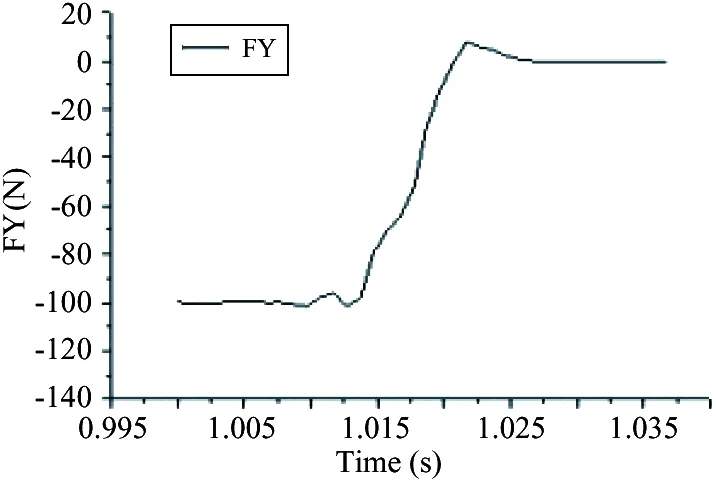
Fig.5 Force in Y direction

Fig.6 Force in Z direction
Rotation speed of the two rollers can be achieved from FEM analysis. As shown in Fig.7, the average rotation speed of hard roller is 12.62 rad/s, and the average rotation speed of soft roller is -12.51 rad/s, thus the rotation speed difference is 0.11 rad/s.
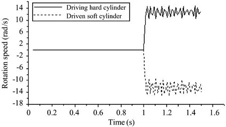
Fig.7 Two rollers’ rotation speed
1.2 Experiment analysis
1.2.1 Experiment
The right two rollers in the experiment apparatus in Fig.8 are used to analyze the motion mechanism of two rollers which elasticity is different greatly, right roller is hard, and the other one is soft. Diameters of the two rollers are all 65mm, and are same with the FEM model.
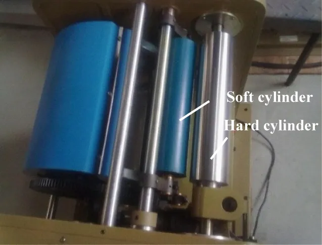
Fig.8 Experiment apparatus
As shown in Table 1, a certain relative sliding exists between the two rollers, and it is consistent with FEM analysis. Deformation of the soft roller, rotation speed of the two rollers, and the relative sliding are increased with the increase of the pressure between the two rollers. That is, with the increase of the rotation speed and soft roller’s deformation, the relative sliding between the two rollers increases too. In this paper, relative sliding is represented by the linear velocity difference.
1.2.2 FEM model verification
A set of data in Table 1 is used to verify the accuracy of the FEM model when pressure is 0.3MPa.
In the FEM model, a displacement of -0.325mm in Y direction is exerted on the hard roller to make it in the state of pressing contact with the soft roller, and its rotation speed is set to be 10πrad/s.
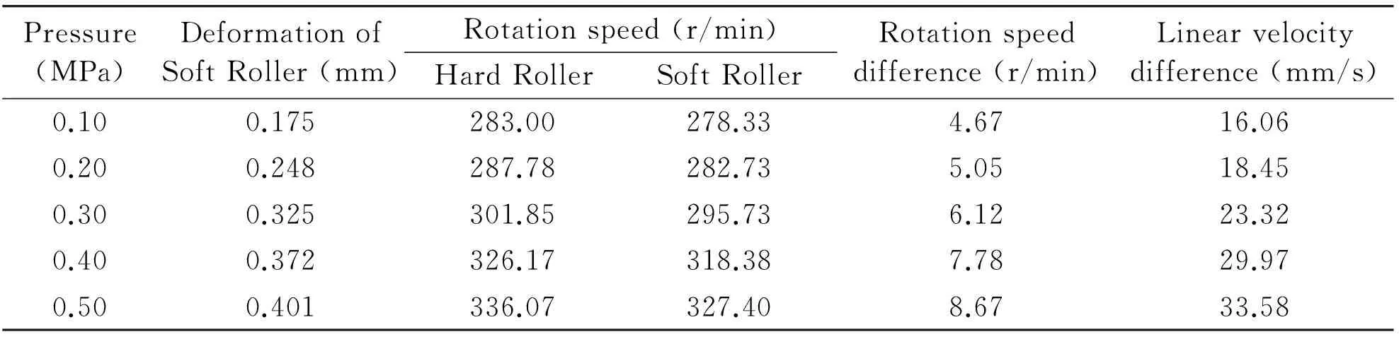
Table 1 Experiment results of two rollers
As shown in Table 2, the speed difference got from the experiment is 6.12r/min, and the speed difference got from the simulation is 5.94r/min. Although a certain error with the experiment condition exists in the simulation model and boundary conditions, the results of simulation and experiment are closed to each other and within the acceptable error range. Therefore the conclusion can be got that the simulation model corresponds to the actual condition, and the analysis result of this model is accurate and reliable.
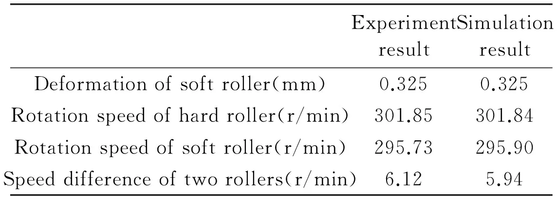
Table 2 Comparison of experiment and simulation analysis
1.3 Influence factors
When the diameter and material of the two rollers are determined, the factors that affect the force and motion of the driven soft roller include the rotation speed of the driving hard roller, and the normal load on the two rollers (radial deformation of the soft roller is decided by it). So in the following analysis the rotation speed of the driving roller and the deformation of the driven roller are changed to analyze the influence of the two factors on the force and motion of the driven soft roller, thus the motion mechanism of the soft roller can be obtained.
1.3.1 Rotation speed of the driving hard roller
Displacement of -0.5mm in Y direction is exerted on the driving hard roller, and its rotation speed is π~10π rad/s.
The soft roller’s tangential force on the initial contact area at different rotation speed is shown in Fig.9. It can be seen that the tangential force increases with the rotation speed, and the maximum value increases from 2N to 23N when the rotation speed increases from π to 10πrad/s. The tangential elastic deformation increases with the tangential force, that means the surface stretching of soft roller when entering into the contact area and the surface compression when leaving the contact area increase too, consequently, the relative sliding increases. As shown in Table 3, with increase of the hard roller’s rotation speed, the relative sliding between the two rollers increases from 2.37mm/s to 43.52mm/s. As shown in Fig.10, the relative sliding increases linearly with the hard roller’s rotation speed, and when the speed reaches to 7π rad/s, the relative sliding increases sharply.

Fig.9 Soft roller’s tangential force
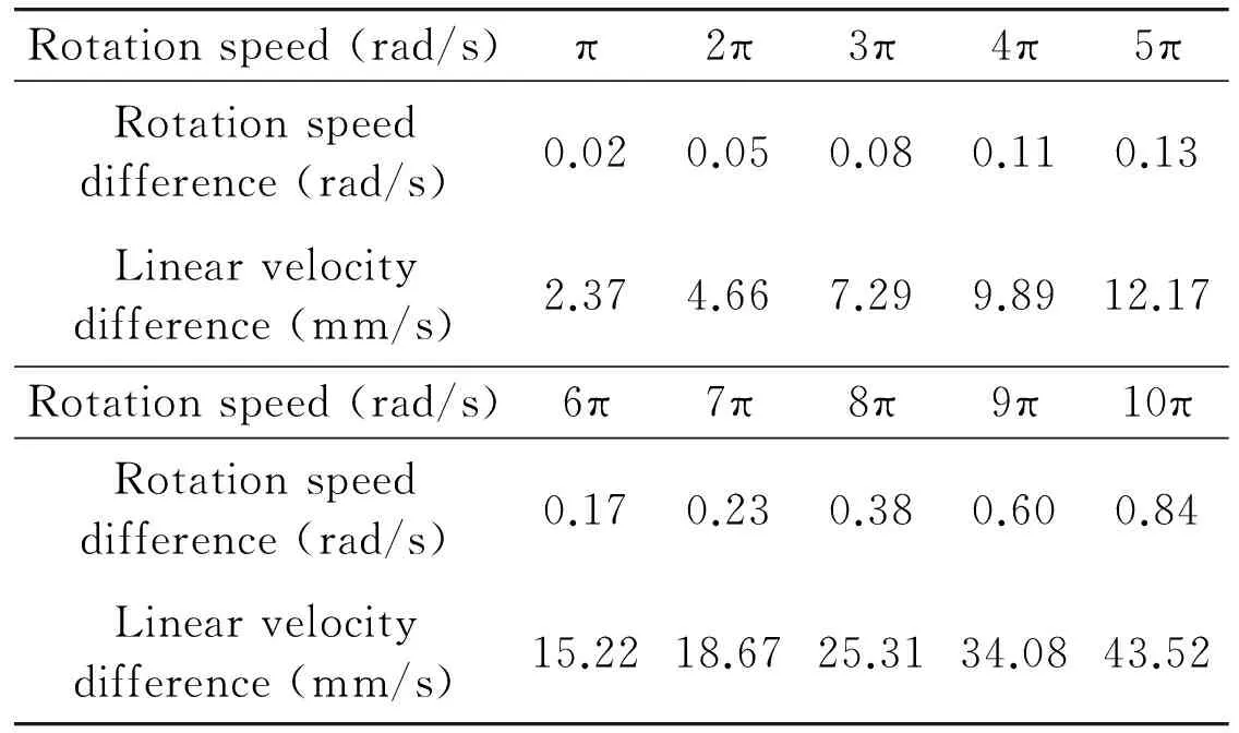
Rotationspeed(rad/s)π2π3π4π5πRotationspeeddifference(rad/s)0.020.050.080.110.13Linearvelocitydifference(mm/s)2.374.667.299.8912.17Rotationspeed(rad/s)6π7π8π9π10πRotationspeeddifference(rad/s)0.170.230.380.600.84Linearvelocitydifference(mm/s)15.2218.6725.3134.0843.52
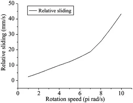
Fig.10 Relative sliding with rotation speed
1.3.2 Deformation of the soft roller
Rotation speed of the driving hard roller is 2π rad/s, displacement of the hard roller in Y direction is from -0.2mm to -0.9mm (it corresponds to the radial deformation of the soft roller).
The soft roller’s tangential force at different deformation is shown in Fig.11. When the radial deformation changes, it is nearly stable, and the maximum value is equal to 5N when the rotation speed is 2π rad/s. That is, at the same driving roller’s rotation speed, the tangential force on the initial contact area of soft roller is almost the same, and the tangential elastic deformation caused by the tangential force is also the same, namely the tangential force has the same influence on the relative sliding.
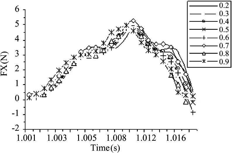
Fig.11 Soft roller’s tangential force at different deformation
Table 4 shows that with the increase of the hard roller’s displacement, that is, the soft roller’s deformation increases, the relative sliding between two rollers increases from 1.98mm/s to 9.60mm/s. And as shown in Fig.12, the relative sliding increases almost linearly with the soft roller’s deformation.
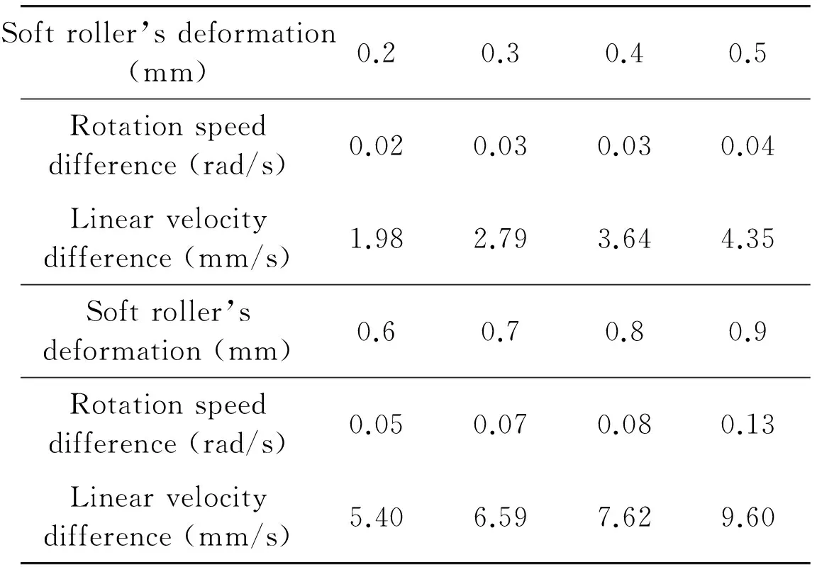
Table 4 Relative sliding with soft roller’s deformation

Fig.12 Relative sliding with soft roller’s deformation
For this condtion, the effect of tangential force on the relative sliding is the same, and the difference of relative sliding is caused by the soft roller’s radial deformation.
1.4 Motion mechanism of two direct-contact rollers
The motion of two direct-contact rollers is mainly decided by the tangential force on the contact area and the deformation of soft roller. When the diameter and material of the two rollers are decided, the tangential force is determined by rotation speed of the driving hard roller, and with the increase of the rotation speed, a larger tangential force on the contact area is needed in order to increase the speed of the driven soft roller, and the tangential elastic deformation increases with the force, then the relative sliding increases. But the tangential force on the contact area of soft roller is approximately the same when the hard roller’s rotation speed is the same while the deformation of the soft roller is different. With the increase of the radial deformation of soft roller, the relative sliding between two rollers increases.
So, it can be concluded that, the relative sliding between two direct-contact rollers with different elasticity, is caused by the tangential elastic deformation and radial elastic deformation of the soft roller.
2 Motion mechanism when two rollers contact indirectly
In actual conditions, maybe the two rollers contact indirectly, and a layer of inter-medium exists between them. For example, in the inking system of a printing machine shown in Fig.1, a layer of ink exists between two ink rollers on the normal working condition, and the two rollers are in the state of indirect contact.
The force and motion of two indirect-contact rollers are analyzed, and compared with the condition of direct contact, the effect of the inter-medium layer on the force and motion of the driven soft roller is achieved.
2.1 FEM analysis
2.1.1 Modeling
FEM model is shown in Fig.13, a rubber layer of 1mm thickness covers the hard roller as the inter-medium between two rollers. And the model of hard roller and soft roller are the same with the above analysis.
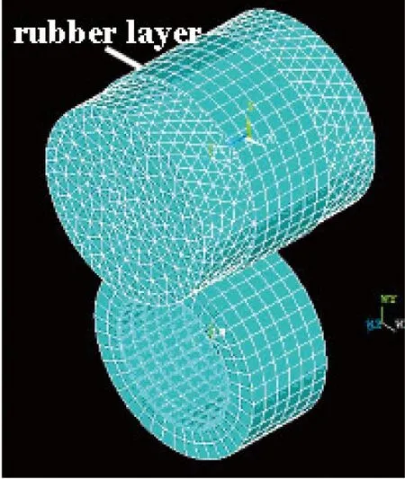
Fig.13 Model of two rollers with a layer of inter-medium
The contact type between outer surface of hard roller and inner surface of rubber layer is binding. And the outer surfaces of the rubber layer and soft roller are a contact pair. The friction coefficient is set to be 0.5.
2.1.2 Force and motion analysis of soft roller
2.1.2.1 Effect of driving roller’s rotation speed on the force and motion
The driving hard roller’s displacement in Y direction is -0.2mm, which can make the two rollers in the state of pressing contact. Rotation speed of the driving hard roller is π ~ 8π rad/s, the hardness of the rubber layer is 50 shore A.
1) Force of the driven soft roller
Soft roller’s tangential force on initial contact area at different rotation speed of driving hard roller is shown in Fig.14. It is similar to Fig.9, and the tangential force increases together with the hard roller’s rotation speed. Fig.15 is the Y directions’ force on the contact area of driven soft roller. The force in Y direction is -27N at the initial moment. With rotation of the two rollers, the rubber layer (inter-medium layer) is compressed to be deformed when it starts to enter into the contact area, then pressure occurrs and exerts on the soft roller, and the Y direction’s force on the contact area of driven soft roller increases to -32N. This is different from the analysis of two rollers on the state of direct contact. With the rotation of the two rollers, the initial contact area gradually turns away from the center squeezing area, so the force in Y direction reduces slowly to zero. Fig.15 also shows that Y direction’s force is not affected by rotation speed of hard roller.

Fig.14 Force in X direction for indirect contact
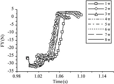
Fig.15 Force in Y direction for indirect contact
2) Deformation of the driven soft roller
Deformation of soft roller is caused by the force in Y direction, and for the 8 conditions, force of soft roller in Y direction is the same (Fig.15), so the deformation is the same. The original radius of the soft roller is 32.500mm, and in Fig.16, the radius before rotation is 32.310mm, and the minimum radius when rotates is 32.297mm. It is consistent with the results of Fig.15, namely, the rubber layer will produce a certain pressure, that will increase the deformation of soft roller.
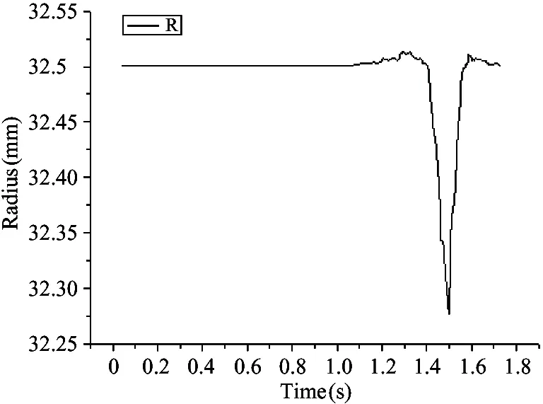
Fig.16 Radius of driven soft roller for indirect contact
3) Relative sliding
As shown in Table 5 and Fig.17, with the increase of the driving hard roller’s rotation speed, the relative sliding between two rollers increases. This result is consistent with the situation of two direct-contact rollers.
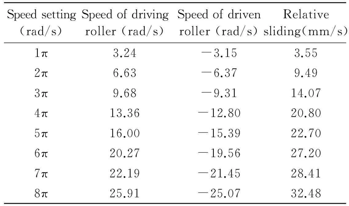
Table 5 Relative sliding with rotation speed for indirect contact
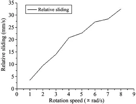
Fig.17 Relative sliding with rotation speed for indirect contact
2.1.2.2 Effect of radial deformation of soft roller on the force and motion
Displacement of the driving hard roller in Y direction is set to be -0.2mm, -0.3mm and -0.4mm to make the hard and soft rollers in the state of pressing contact, that also means the pressure between the two rollers and the radial deformation of the soft roller are changed. Rotation speed of the driving hard roller is 2π rad/s, and the hardness of the rubber layer is 50 shore A.
1) Force and deformation of the driven soft roller
Fig.18 is the soft roller’s force in Y direction on the initial contact area, and with the increase of driving roller’s displacement, force in Y direction increases, and deformation of the driven soft roller increases too, as shown in Fig.19. When the displacement is -0.2mm, -0.3mm and -0.4mm, the corresponding minimum radius of soft roller is 32.297mm, 32.210mm and 32.140mm. As shown in Fig.20, the maximum value of the tangential force is nearly the same, it is consistent with the situation of direct-contact shown in Fig.11. It illustrates that the tangential force of driven soft roller is affected by the driving hard roller’s rotation speed, but not relevant to the deformation of driven soft roller.
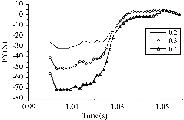
Fig.18 Force in Y direction for indirect contact
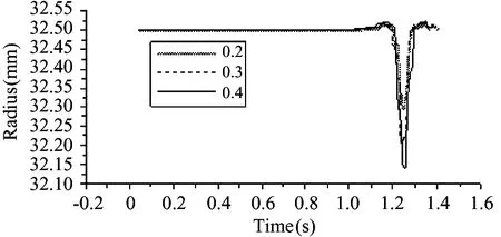
Fig.19 Radius of soft roller for indirect contact
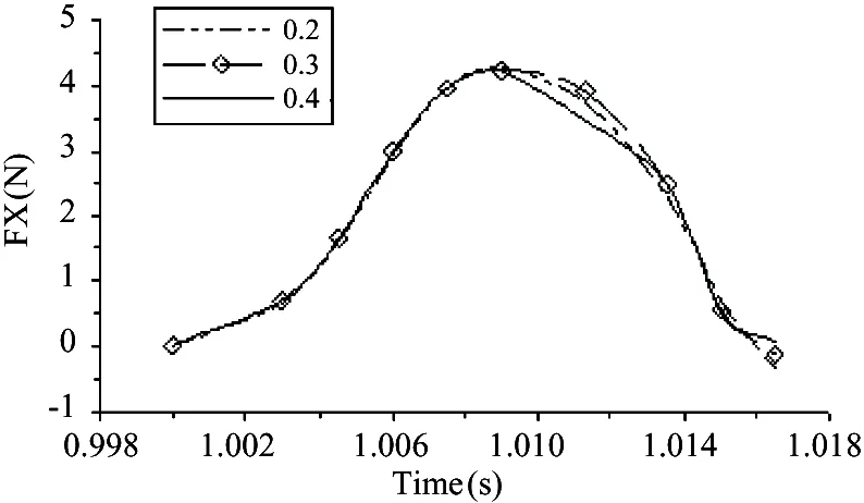
Fig.20 Force in X direction for indirect contact
2) Relative sliding
With the increase of the driving roller’s displacement, that is, radial deformation of the driven soft roller, the relative sliding increases from 9.49mm/s to 11.67mm/s, as shown in Table 6 and Fig.21.
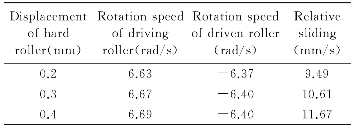
Table 6 Relative sliding with deformation for indirect contact
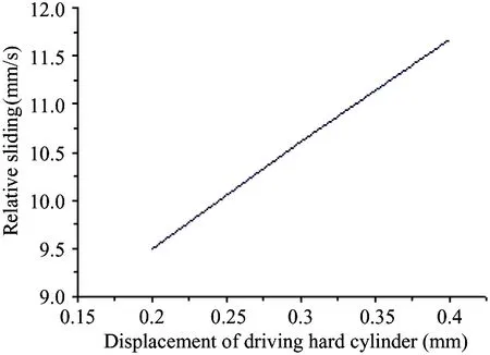
Fig.21 Relative sliding with deformation for indirect contact
2.1.2.3 Effect of rubber layer’s hardness on the force and motion
The hardness of the rubber layer is set to be 40, 45, 50 shore A. The hard roller’s displacement is -0.2mm, and its rotation speed is 2π rad/s.
1) Force and deformation of the driven soft roller
The soft roller’s tangential force at different hardness of rubber layer is shown in Fig.22. The maximum value of the force is the same for different rubber layer hardness. It illustrates that the tangential force of soft roller is not relevant to the hardness of rubber layer. Fig.23 is the soft roller’s force in Y direction. For the same displacement of hard roller, higher hardness rubber layer needs greater force than the lower hardness rubber layer to have the same deformation, thus the corresponding force in Y direction is different. The force at hardness of 50 shore A is bigger than the force at hardness of 40 shore A, but the difference is small,
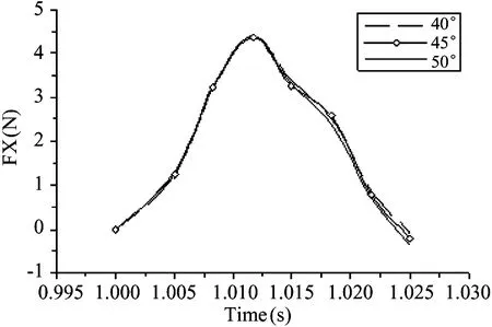
Fig.22 Force in X direction for indirect contact
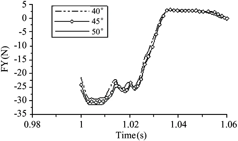
Fig.23 Force in Y direction for indirect contact
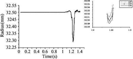
Fig.24 Radius of soft roller for indirect contact
so the deformation of the soft roller is nearly the same, as shown in Fig.24, when the hardness is 40, 45, 50, the corresponding radius of soft roller is 32.319mm, 32.299mm and 32.297mm respectively.
2) Relative sliding
As shown in Table 7 and Fig.25, with the increase of hardness of rubber layer, the relative sliding decreases from 10.05mm/s to 9.49mm/s. For the different hardness of rubber layer, the tangential force and force in Y direction are almost the same, and the tangential and radial elastic deformation of the soft roller are also almost same. But the lower the hardness of the rubber layer is, its tangential elastic deformation is bigger, and the rubber layer and the soft roller are a contact pair, the rubber layer bonds to the hard roller, so it makes the relative sliding between the hard roller and soft roller increases.

Table 7 Relative sliding with hardness for indirect contact
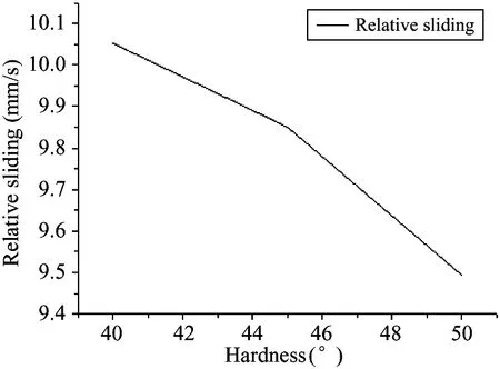
Fig.25 Relative sliding with hardness for indirect contact
2.2 Comparison of direct contact and indirect contact
2.2.1 Comparison of simulation results
In the model of direct contact, the hard roller’s displacement is set to be -0.2mm, its rotation speed is 4π, 5π, 6π, 7πrad/s.
From the analysis, in the model of direct contact, the soft roller is deformed under the press of the hard roller, and the minimum radius of the soft roller is 32.300mm. But the radius is 32.297mm on the same conditions in the indirect model (shown in Fig.16). It illustrates that the rubber layer produces pressure on the soft roller and increases its radial deformation. Table 8 is the results of two roller’s rotation speed in the direct contact model. Fig.26 is the comparison of Table 8 (direct contact) and Table 5 (indirect contact). From Fig.26, the relative sliding of indirect contact is greater than that of direct contact.

Table 8 Rotation speed of two rollers for direct contact
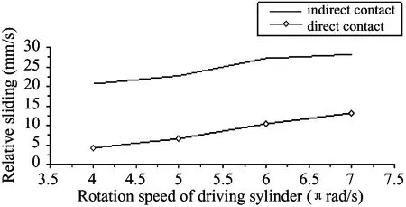
Fig.26 Relative sliding comparison from simulation
2.2.2 Comparison of experimental results
In the above experiment apparatus shown in Fig.8, there is a layer of ink between the two rollers, and the two rollers are in the state of indirect contact. The rotation speed of the two rollers are measured.
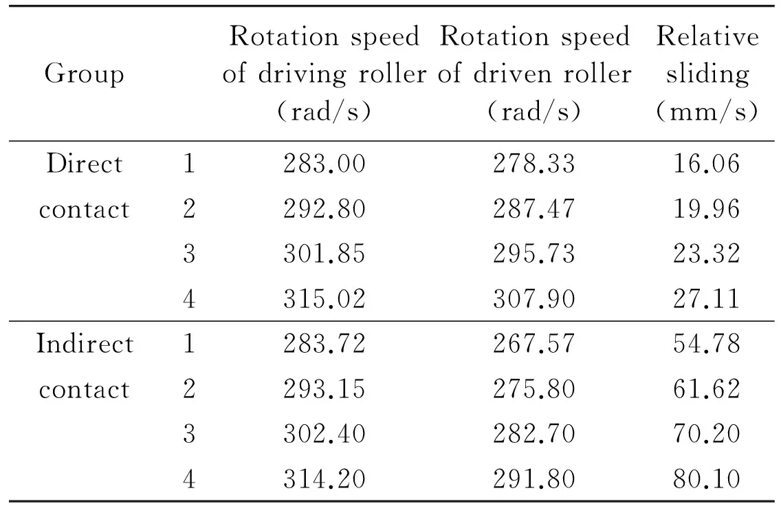
Table 9 Rotation speed of two rollers from experiment
As shown in Table 9, the relative sliding increases with the increase of rotation speed of two rollers on both the conditions of direct and indirect contact, but the relative sliding on the condition of indirect contact is obviously greater than that on the condition of direct contact, as shown in Fig.27. The experimental results are consistent with the results of simulation.

Fig.27 Relative sliding comparison from experiment
2.3 Motion mechanism of two indirect contact rollers
The rubber layer between two rollers is compressed when it starts to enter into the contact area, and the compression makes the rubber layer deform thus there is pressure produced by the rubber layer exerting on the soft roller, that will increase the radial deformation of soft roller, therefore the relative sliding is greater than that on the condition of direct contact. The smaller the hardness of the rubber layer is, the greater the tangential elastic deformation of the rubber layer is, thus the relative sliding between the two rollers is greater.
When there is a soft inter-medium layer between the hard roller and soft roller, the motion mechanism can also be used to interpret the motion characteristics of two soft rollers: when two soft rollers contact each other in the state of pressing, the relative sliding is bigger than the relative sliding when two hard rollers contact or a hard roller and a soft roller contact. And for any conditions, the relative sliding always increases with the decrease of the hardness of the soft roller or the inter-medium layer.
3 Motion characteristics for multiple contact areas
Motion mechanism of two rollers both on the condition of direct and indirect contact is analyzed above. In the actual condition, maybe a roller contacts with more than one roller, for example, in Fig.1, rollers 6 contacts with rollers 3, 9 and 7, so it is necessary to analyze the motion characteristics when there are more than one contact area.
3.1 FEM model
As shown in Fig.28, a model of 5 rollers is established to analyze the force and motion of roller 2. Roller 1 is hard, Roller 2 is soft, and there is a layer of rubber between them, and the model is the same with the above analysis. Roller 3 and 4 are hard, their diameter is 45mm. Roller 5 is soft, its diameter is the same with Roller 2.
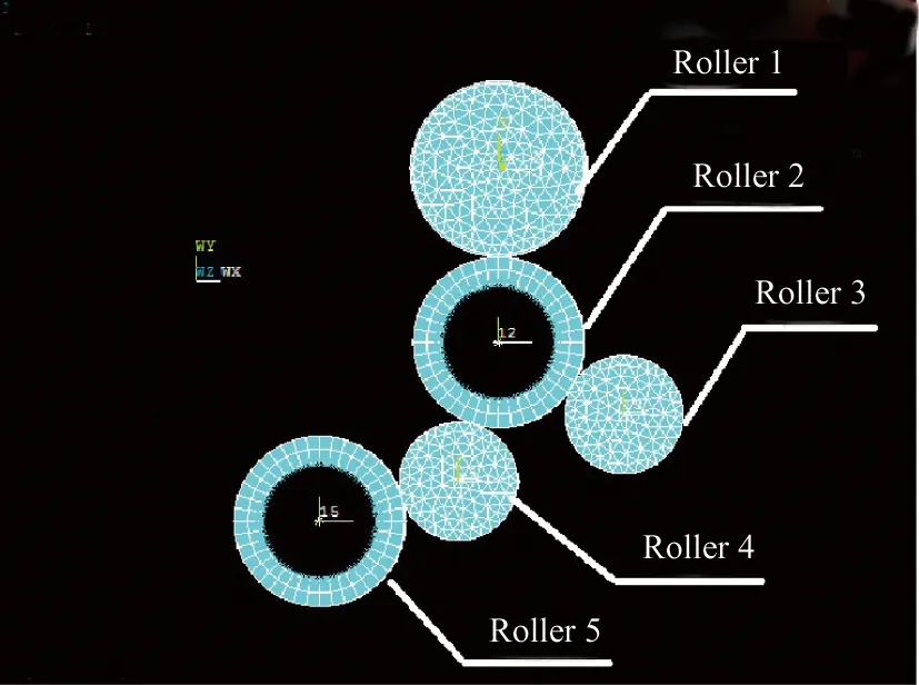
Fig.28 Finite element model for five rollers
3.2 Simulation analysis
3.2.1 Force analysis
Displacement of Roller 1 in Y direction is -0.2mm, its rotation speed is 2π rad/s, the hardness of rubber layer is 50 shore A. All the rollers are in the state of pressing contact.
As shown in Fig.29, the maximum value of tangential force on the initial contact area of Roller 2 is about 7N, and it is about 4N in the model of two roller on the same condition (shown in Fig.14). In the model of five rollers, hard Roller 1 is the driving roller, it drives all the driven rollers by the power transmitted through frictions between rollers, that is, Roller 1 drives Roller 2, Roller 2 drives Roller 3 and 4. So when the rotation speed is 2π rad/s, it needs greater tangential force to drive more rollers, that is why the tangential force in the model of five rollers is greater than that in the model of two rollers. So it can be deduced that with the increase of the number of contact area, greater tangential force is transmitted to drive more rollers, and that will also affect the motion of the rollers.
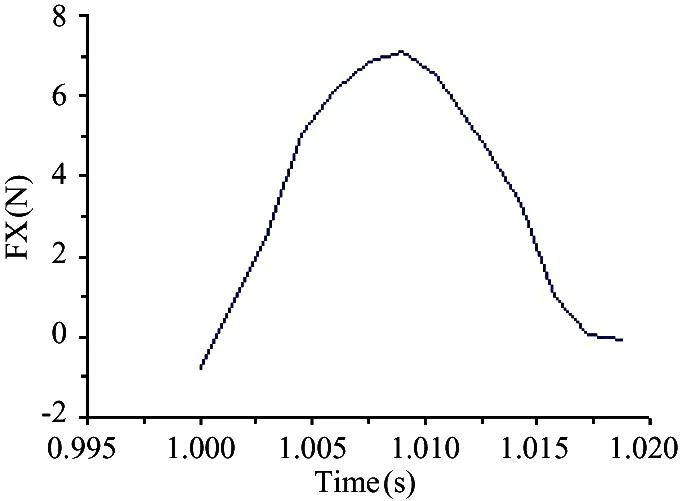
Fig.29 Force in X direction for the model of five rollers
As shown in Fig.30, the force in Y direction is consistent with that in the model of two rollers.
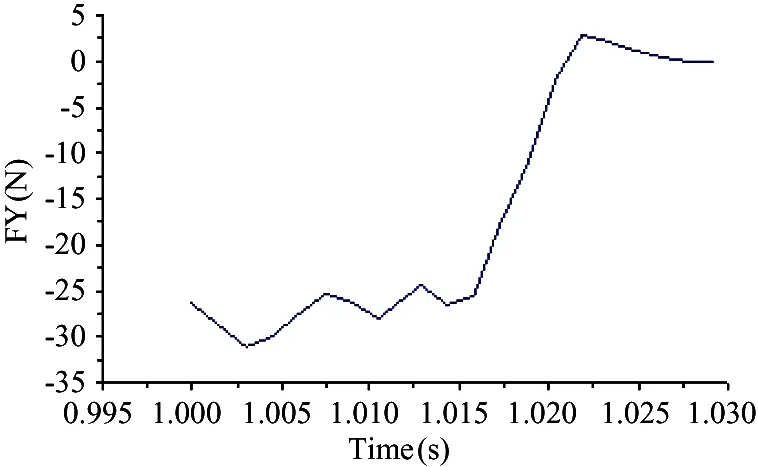
Fig.30 Force in Y direction for the model of five rollers
3.2.2 Motion analysis
Displacement of driving hard Roller 1 in Y direction is -0.2mm, all the five rollers are in the state of pressing contact. The rotation speed of hard Roller 1 is 2π, 3π, 4π rad/s, and the hardness of rubber layer is 50 shore A。
1) Deformation of soft Roller 2
As shown in Fig.31, the minimum radius of soft Roller 2 is 32.294mm. And for the model of two rollers, the minimum radius of soft Roller 2 on the same condition is 32.297mm (shown in Fig.16). So in the model of 5 rollers, that is, there is more than one contact area, the deformation of soft Roller 2 increases because of pressing contact with the other two rollers.
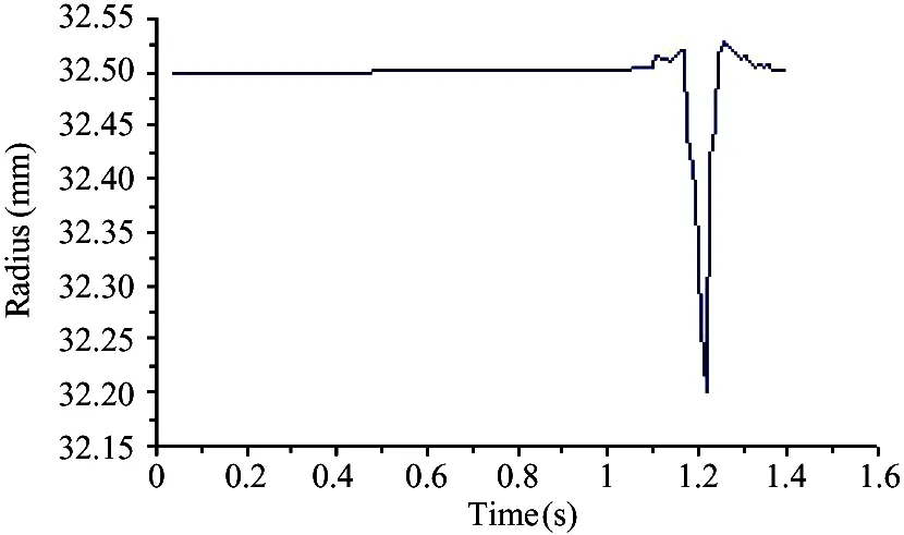
Fig.31 Radius of Roller 2 for the model of five rollers
2) Relative sliding
From Table 10, the relative sliding between hard Roller 1 and soft Roller 2 increase with the rotation speed of hard Roller 1. From Fig.32, relative sliding in the model of five rollers is obviously lower than that in the model of two rollers. In the model of five rollers, there is also pressing contact between soft Roller 2 and hard Roller 3 and 4, and the contact area of soft Roller 2 increases. This will restrain the relative sliding between rollers. So the relative sliding in the model of five rollers is smaller than that in the model of two rollers. And in the model of five rollers, the effect of tangential force on the relative sliding is much smaller than that of the contact area.
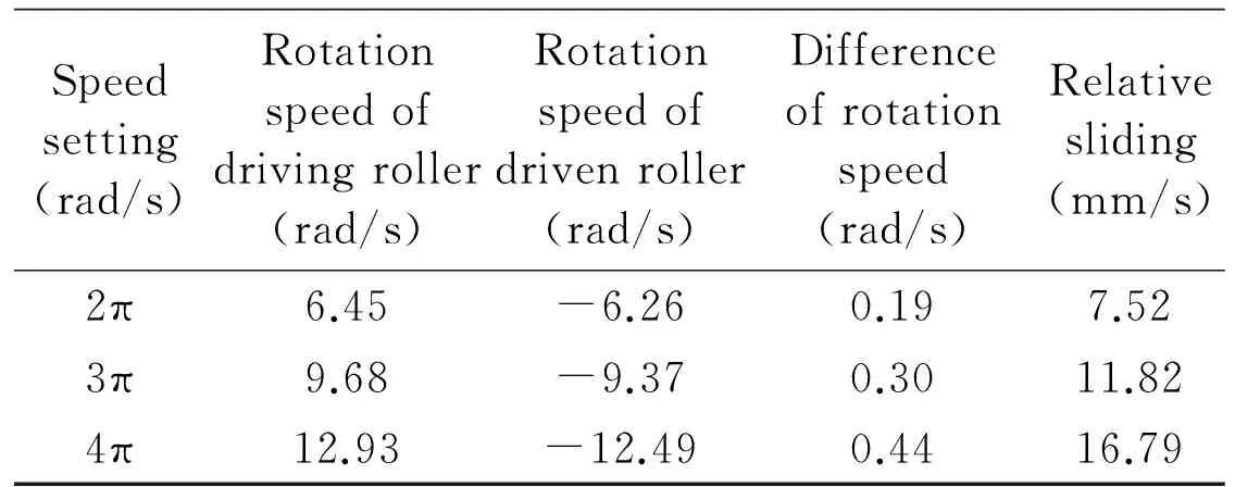
Table 10 Rotation speed of two rollers for the model of five rollers
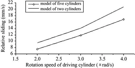
Fig.32 Relative sliding for the model of five rollers
4 Conclusions
Using the method of FEM and experiment, the motion mechanism of two rollers with big difference of elasticity is analyzed. The following conclusion is got from the analysis.
(1) The motion of two direct-contact rollers is mainly affected by the tangential force on the contact area and the radial deformation of soft roller.
(2) When the hard roller and soft roller are in the state of indirect contact, the relative sliding is greater than that on the condition of direct contact. And the smaller the hardness of the inter-medium layer is, the greater the relative sliding between the two rollers is.
(3) When there are more than one roller contacting with the soft roller, with the increase of the contacting rollers, the relative sliding decreases.
In some cases, maybe the rollers not only rotate but also move in the axial direction, so the future research is about the effect of movement in the axial direction on the force and motion of the rollers.
[ 1] Liu Z L. Principles of tribology. Beijing: Higher Education Press, 2009. 97-104
[ 2] Valentin L. Popov. Contact mechanics and friction physical principles and applications. Beijing: Tsinghua University Press, 2011. 7-55
[ 3] Wei L, Liu Q H, Zhang P G. Sliding friction surface contact mechanics model based on fractal theory. Journal of Mechanical Engineering, 2012, 48(17):106-113
[ 4] Wang Z C. A mechanism of rolling friction and the coefficient of rolling friction. Journal of Shanghai Institute of Mechanical Engineering, 1993, 15(4):35-43
[ 5] Wang Y, He Z, Wang G X. A practical friction model. Electric Machines and Control, 2011,15(8):59-63
[ 6] Dong Y C, Cui J K, Li K, etc. Study on sliding ratio of the straight conjugate internal gear pair. Machinery Design and Manufacture, 2006,(7):9-11
[ 7] Li H X. Fundamental Theory and Experiments Study on Involute-circular Gear [Ph.D dissertation]. Chongqing: Chongqing University, 2012:43-50
[ 8] Chen G X, Shi X Y. An experimental study of the relation between friction force and relative sliding speed. Lubrication Engineering, 2002,(3):44-45,48
[ 9] Yang X Q, Li X L. Modern finite element theory and engineering application. Beijing: Beihang University Press, 2007. 138-144
[10] Mao Q D, Li Z Q. Mechanical designer handbook. Beijing: China machine Press, 2007. 22-23
Chu Hongyan, born in 1972. She received her Ph.D degrees in Beijing University of Technology, in 2003. She also received her B.S. and M.S. degrees from Jilin University of Technology in 1994 and 1997 respectively. Her research interests include sheet metal forming, production planning and scheduling, and printing colour quality control.
10.3772/j.issn.1006-6748.2015.04.003
①Supported by the National Science and Technology Supporting Program (2012BAF13B05-1) and the National Natural Science Foundation of China (No. 51105009).
②To whom correspondence should be addressed. E-mail: chuhongyan@bjut.edu.cn Received on Sep. 2, 2014, Zhao Juntao, Cai Ligang
猜你喜欢
杂志排行

High Technology Letters的其它文章
- Magnetometer calibration algorithm based on ellipsoid constraint①
- Two-stage DOA estimation method for passive radar based on sparse representation①
- Study and application of vibrating wire strain gauge in monitoring cable tension of FAST cable-net①
- Service optimization in programmable cloud network①
- Design of bilayer lengthened LDPC codes over expanded graph for relay channels①
- Effect of laser heating on the microstructure and hardness of TRIP590 advanced high strength steel used for roll forming①