Analysis of ink flow channel between two rotating ink rollers①
2015-04-17ChuHongyan初红艳
Chu Hongyan (初红艳)
(College of Mechanical Engineering and Applied Electronics Technology, Beijing University of Technology, Beijing 100124, P.R.China)
Analysis of ink flow channel between two rotating ink rollers①
Chu Hongyan (初红艳)②
(College of Mechanical Engineering and Applied Electronics Technology, Beijing University of Technology, Beijing 100124, P.R.China)
In order to research how the size of the ink flow channel is affected by the interaction of adjacent ink areas, according to the method of fluid-solid interaction, this paper analyzes the size of the ink flow channel of two ink rollers’ rotation. Firstly, this paper simulates the situation of only one ink area. Secondly, this paper simulates the situation of five adjacent ink areas. Then, through comparing the simulation results of two above situations, it’s obvious that the interaction of adjacent ink areas has big effects on the ink pressure and the size of ink flow channel. At last, this paper gets the main factor that affects the size of ink flow channel in the different situations.
offset printing machine, ink roller, ink flow channel, adjacent ink areas, numerical simulation
0 Introduction
With the development of science and technology, the printing industry has developed rapidly in recent years, and the quality of printing product gets more and more attention in our society. In the printing process, a key aspect to ensure the print quality is to maintain the stability, uniformity and moderation of the ink transfer[1].
In the inking system, the ink transfer depends on the pressure between two ink rollers and the rollers’ rotation. The pressure between both rollers squeezes the ink in the circumferential and axial direction. At the same time, the ink will produce correspondingly counterforce to ink rollers to some extent, which will cause changes in the size and the shape of the soft ink roller. That is to say, the corresponding ink flow channel is changed by the ink load, as shown in Fig.1. And this will cause changes in the ink amount of flowing through the ink flow channel[2]. So the research of the size of the ink channel has an important signification to ensure the amount of ink transfer.
According to the method of fluid-solid interaction, Ref.[3] simulates the process by which the ink flows through two mutual squeezing rollers at the initial moment. And through extracting the deformation values of the soft roller, the size of ink flow channel is made sure. But the image of the printing product is different, and the ink amount to be used is also different, so the printing product is divided into a number of regions in horizontal direction, and the region is called ink area[4], as shown in Fig.2. In printing process, the ink amount to be used in ink areas is different, and the ink-feeding in ink areas is different as well, then the adjacent ink area will influence each other.
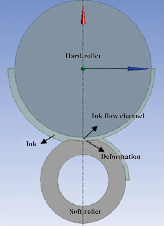
Fig.1 Deformation schematic of soft roller
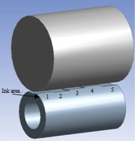
Fig.2 Schematic of different ink areas
1 Fluid-solid interaction theory and research methods
The fluid-solid interaction[5]is a branch of mechanics which combines fluid mechanics and solid mechanics. The important feature is the interaction of two phase mediums. The fluid load causes the deformable solid structure to deform or move, and this kind of deformation and movement affects the fluid flow, so the distribution and size of the fluid load are changed, which is the liquid-solid interaction phenomenon.
The analysis of fluid-solid interaction is divided in two kinds of methods[6]: one-way fluid-solid interaction and two-way fluid-solid interaction. The one-way fluid-solid interaction is suitable for the situation that the solid deformation caused by the fluid is not big, that is to say, the change of fluid boundary is very small. But when the solid deformation caused by the fluid is larger, the fluid boundary is changed, and the fluid distribution is obviously changed, the two-way fluid-solid interaction is more suitable.
According to the one-way fluid-solid interaction method in Ref.[3], this paper researches the process by which ink flows through two mutual squeezing rollers at the initial moment, and analyzes the deformation of soft roller caused by the ink load, and then gets the size of ink flow channel.
1.1 Mathematical model of fluid
Because the ink is continuous medium and incompressible non-Newtonian fluid, the incompressible Navier-Stokes equation is chosen as a computational model[7]. This equation summarizes the universal law of incompressible viscous fluid. Here is the rectangular form of the incompressible Navier - Stokes equations, including continuity equation and momentum equation, expressed as follows:
(1)
(2)
where ρ is fluid density, μ,ν,ω are velocity components on the x, y, z directions, fx, fy, fzare three directions of the volume force, p is isotropic pressure and u is the kinetic viscosity coefficient.
1.2 Mathematical model of solid
The outside of the soft roller is a rubber layer that covers a steel roller. This paper just builds the rubber part only so it belongs to the nonlinear elastic solid.
In the case of deformation, a rectangular coordinate system x-y-z is established. The (x, y, z) is the location of the center of gravity, and point to the normal direction on the front and side face. The force balance equation is as below[8]:
(3)
where σi(i=x,y,z)and τi(i=xy,xz,yz)are the normal stress and shear stress of the corresponding direction; Fi(i=x,y,z)is the external force.
2 Analysis of ink flow channel at the initial time
At the initial time of ink transfer, that is, before the ink flows through two ink rollers, a layer of ink covers the left side of the hard roller, as shown in Fig.3. Then with the rotation of rollers, the ink is transferred from the hard roller to the soft roller. And under the ink pressure and the squeeze pressure between two rollers, the soft roller has a deformation. Then there is a gap called ink flow channel between the two rollers. With the rotation of rollers, the ink flows through the gap, and then a layer of ink is attached to the right side of each ink roller.
In this paper, the soft roller is already deformed under the pressure between two rollers at the initial time. The hard roller is a driving roller, and its radius is 40mm, and it rotates counterclockwise at the speed of 261.8mm/s. The soft roller is the driven roller. Its rubber part is built. The outer radius is 25mm and the inner radius is 15mm. It rotates clockwise at the speed of 261.8mm/s driven by the rotation of the hard roller.
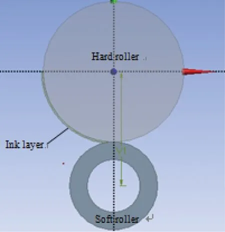
Fig.3 Geometry of rollers and ink at the initial time
According to the one-way fluid-solid interaction method in Ref.[3], this paper analyzes the deformation of soft roller caused by the ink pressure. And the deformation is also the size of ink flow channel. The situation of only one ink area is analyzed. Fig.4 is the ink pressure intensity picture got by using the fluid simulation software CFX, for the situation of 0.242mm ink layer on the left side of the driving roller at the initial time. At the initial time of the ink transfer, the ink pressure gradually increases along the rotation direction of the hard roller. And at the fluid-solid interaction interface the ink pressure reaches the maximum.
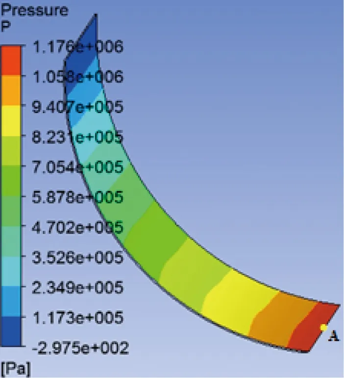
Fig.4 The ink pressure intensity chart
The ink pressure of the fluid-solid interaction interface (as shown in Fig.5) loads on the corresponding
position of the soft roller, as shown in Fig.6, face A is the fluid-solid interaction interface. The deformation of the contact area on the soft roller, that is, the size of the ink flow channel between two rollers, is decided by the pressure on the fluid-solid interaction interface. And pressure F is decided by pressure intensity P on the fluid-solid interaction interface and the area of the interface S, F=P×S.
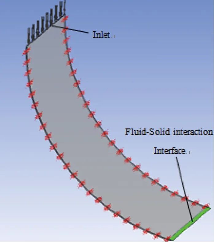
Fig.5 Model of ink layer
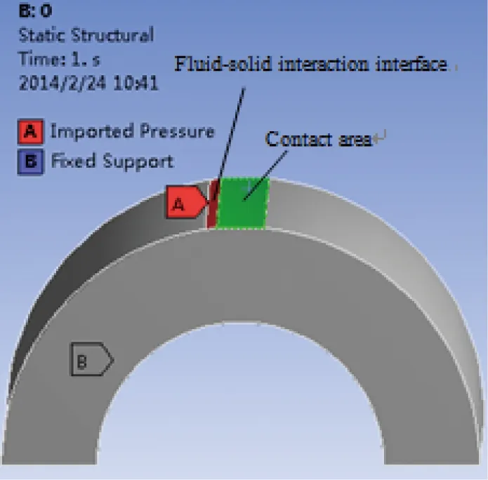
Fig.6 Model of soft roller
Fig.7 is the deformation of the contact area along the Y axis under the ink pressure. Because of the ink pressure, the deformation of the soft roller is along the negative direction of the Y axis, which is why the deformation value is negative. For the situation of 0.242mm ink layer on the left of the hard roller, through extracting the deformation value of the contact area, the deformation average 0.0561mm is got, that is to say, the size of the ink flow channel is 0.0561mm.

Fig.7 Rubber roller’s deformation
3 Effect of the ink thickness on the ink flow channel
In order to analyze how the ink thickness affects the ink flow channel at the initial time, based on the above method, four situations are analyzed and compared, as shown in Table 1.
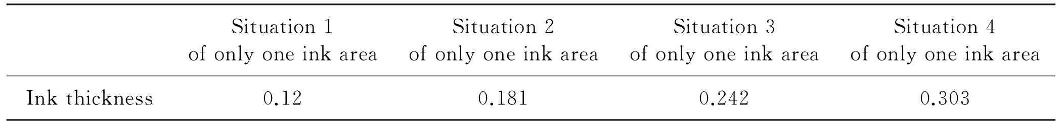
Table 1 Ink thickness at the initial time(mm)
3.1 Ink pressure analysis
The ink pressures of different situations are extracted, as shown in Fig.8. They have the same distribution with Fig.4. As can be seen from Fig.4 and Fig.8, with the increase of the ink thickness, the ink pressure gradually decreases. For example, in different situations, the ink pressure of point A (-0.00247, -0.0399, 0.05)(mm) is as Table 2. It’s obvious that because of the difference of the ink thickness, the ink pressure is much different.
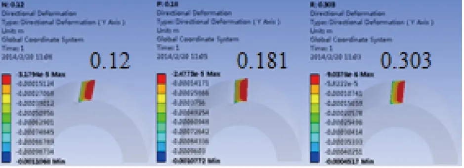
Fig.8 Ink pressure intensity of different situations
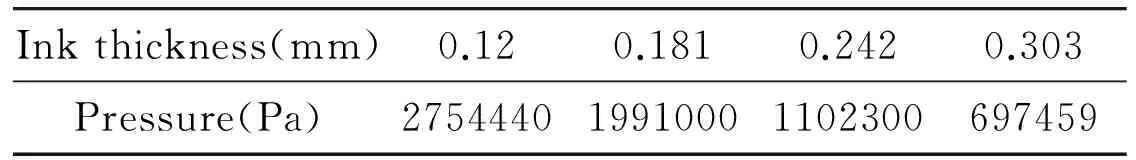
Inkthickness(mm)0.120.1810.2420.303Pressure(Pa)275444019910001102300697459
3.2 Roller deformation analysis
The contact area’s deformations of different situations are extracted, and they have the same distribution with Fig.5. At the initial time of the ink transfer, the larger the ink thickness is, the smaller the deformation of the soft roller is.
The deformation of the contact area is decided by the product of pressure intensity P on the fluid-solid interaction interface and the area of interface S. The larger the ink thickness is, the larger the area of the interface is. But compared with the change of the pressure intensity caused by different ink thickness, the change of the area of the interface is small. So the main influence factor is the intensity of the pressure. The larger the ink thickness is, the smaller the ink pressure is, and the smaller the deformation of the soft roller is.
The deformation values of the contact area in different situations are extracted. Through calculating the average deformation value, the size of ink flow channel is got, as shown in Table 3.

Table 3 Size of the ink flow channel in the different situations
4 Effect of the interaction of adjacent ink areas on the ink flow channel
For the situation of multiple ink areas, the interaction of adjacent ink areas on two rotating rollers is analyzed in this section. According to the analysis result in Ref.[9], considering the rotation speed of ink rollers and the ink length, two situations of five adjacent ink areas are simulated, as shown in Table 4. The first situation is that the adjacent sides of the middle ink area have the same ink thickness and each is larger
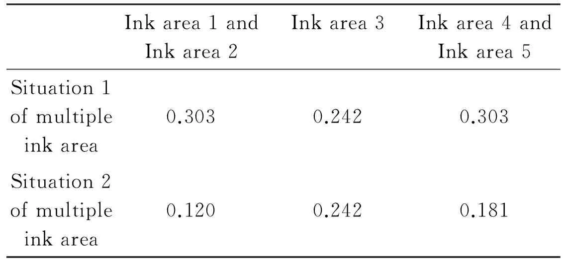
Table 4 The ink thickness at the initial time(mm)
than that of the middle area. The second situation is that the adjacent sides of the middle ink area have different ink thickness and each is smaller than that of the middle area.
4.1 Pressure analysis
Fig.9 and Fig.10 are pressure intensity charts of the ink on the left of the hard roller. In the above figures, along the positive direction of the Z axis, they are the ink area 1~5. As can be seen from above figures, the situation of multiple ink areas has the same pressure distribution with the situation of only one ink area. The larger the ink thickness is, the smaller the ink pressure is. And the larger the ink thickness difference of adjacent ink areas is, the larger the ink pressure difference of adjacent ink areas is. Take situation 2 of multiple ink areas as an example. The pressure at the middle position of every ink area is extracted, as shown in Fig.11.
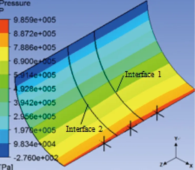
Fig.9 The ink pressure intensity chart of the situation 1 of mulitiple ink area
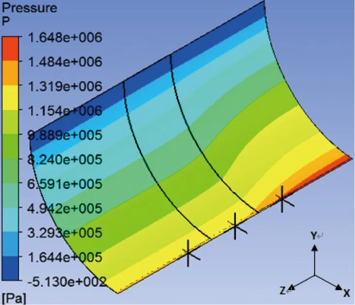
Fig.10 The ink pressure intensity chart of the situation 2 of mulitiple ink area
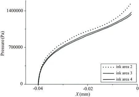
Fig.11 The ink pressure curve of the situation 1 of multiple ink area
Fig.12 and Fig.13 are the axial ink flow speed charts of ink area interfaces. The horizontal axis is the coordinate of X axis in Fig.9 and Fig.10 and the vertical axis is the axial ink flow speed. The pressure difference between the adjacent ink areas can cause axial ink flow. As it can be seen from the figures, ink flows from the ink area that is of larger ink pressure to the ink area of smaller ink pressure, that is, the ink flows from the ink area of smaller ink thickness to the ink area that is of larger ink thickness. And the axial ink flow is the strongest near the fluid-solid interaction interface. In addition, for situation 1 of multiple ink areas, ink area interfaces have the same pressure difference, so they have the same axial ink flow speed. But for situation 2 of multiple ink areas, the ink thickness difference of interface 1 is larger than that of interface 2, so the axial ink flow of interface 1 is larger than that of interface 2.
For the middle ink area, when the ink thickness of adjacent ink areas is larger than that of the middle ink area, the ink of the middle ink area flows to its two adjacent ink areas, the pressure of the middle ink areas releases, and decreases correspondingly. But when the ink thickness of adjacent ink areas is smaller than
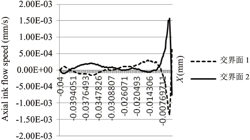
Fig.12 The axial ink flow speed of the situation 1 of mulitiple ink area
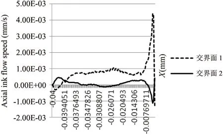
Fig.13 The axial ink flow speed of the situation 2 of mulitiple ink area
that of the middle ink area, the ink of adjacent ink areas flows to the middle ink area, the pressure of adjacent ink areas releases, and the pressure of the middle ink area increases correspondingly.
For example, take a point at the middle position on fluid-solid interaction interface of each ink area, the pressure of this point is shown in Table 5. Comparing Table 5 with Table 2, it can be seen that the situation of multiple ink areas has the same pressure distribution with the situation of only one ink area. The larger the ink thickness is, the smaller the ink pressure is. But because of the axial ink flow, the pressure difference of the adjacent ink areas is very small.
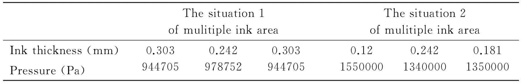
Table 5 The pressure of the middle point on the fluid-solid interaction interface
4.2 Deformation analysis
Fig.14 and Fig.15 are the deformation of the soft roller caused by the pressure of the left ink layer on the hard roller. It can be seen from the figures that the more far away from the fluid-solid interaction interface, the smaller the deformation is. Fig.16 is the deformation distribution curve of the middle symmetrical line on the contact area. The horizontal axis is the coordinate of Z axis, and the vertical axis is the deformation value. Because of the deformation along the negative direction of Y axis, the deformation value is negative.
In Section 3.2 that only considers one ink area, the larger the ink thickness of the ink area is, the smaller the deformation of the soft roller is. But it can be seen from Fig.16 that considering multiple ink areas, the larger the ink thickness of the ink area is, the larger the deformation of the soft roller is.
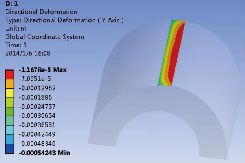
Fig.14 The soft roller’s deformation of the situation 1 of mulitiple ink area
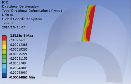
Fig.15 The soft roller’s deformation of the situation 2 of mulitiple ink area
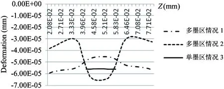
Fig.16 The soft roller’s deformation in the axial direction
The deformation of the contact area is decided by the product of the pressure intensity P on the fluid-solid interaction interface and the area of the interface S. For the situation of only one ink area, compared with the difference of the pressure intensity caused by different ink thickness, the difference of the area of the interface is small. So the main influence factor is the ink pressure intensity. The larger the ink thickness is, the smaller the ink pressure is, and the smaller the deformation of the soft roller is.
But for the situation of multiple ink areas, because of the axial ink flow, the pressure difference of adjacent ink areas is very small. So the main influence factor is the area of the fluid-solid interaction interface. The larger the ink thickness is, the larger the area of the fluid-solid interaction interface is, and the larger the deformation of the soft roller is.
For the middle ink area, the area of the fluid-solid interaction interface is not changed. when it is affected by adjacent ink areas of larger ink thickness, its ink pressure decreases, and the deformation of the soft roller also decreases accordingly; when it is affected by adjacent ink areas of smaller ink thickness, its ink pressure increases, and the deformation of the soft roller also increases accordingly.
The deformation value of the contact area in different situations is extracted. Through calculating the average deformation value, the size of ink flow channel is got, as shown in Table 6.
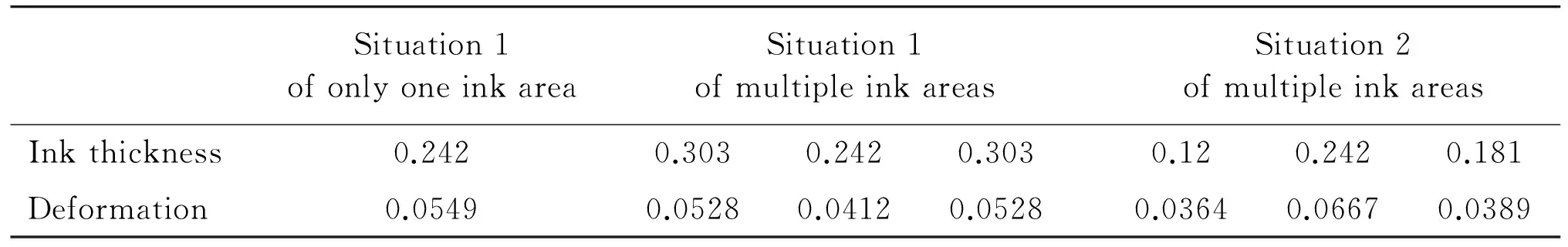
Table 6 The average deformation value of different situations (mm)
4.3 Analysis of ink flow channel at the normal time
At the initial time of ink transfer, soft roller deforms caused by the ink pressure. The ink flows through the gap between two rollers, and covers the right side of each roller. With the rotation of ink rollers, a layer of ink is attached to the left side of soft roller, and participates in the following ink distribution and transfer. The ink thickness of roller outlet at the initial time is as the ink thickness of roller inlet at the normal time, as shown in Fig.17.
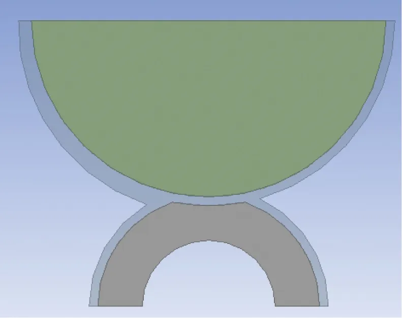
Fig.17 Model of ink and roller at the normal time
According to above fluid-solid interaction method, the size of ink flow channel at the normal time is got. And through comparing the size of the normal time with that of the initial time, it’s obvious that the size difference is very small and is negligible.
5 Conclusions
The research of the size of the ink channel in the printing process has an important signification to ensure the amount of ink transfer. Through analysis of this paper, the conclusions below are got.
(1) The size of the ink flow channel between two ink rollers is decided by the pressure intensity on the fluid-solid interaction interface and the area of the interface.
(2) For the situation of only one ink area, the main influence factor on the deformation of the soft roller is the pressure intensity. The larger the ink thickness is, the smaller the ink pressure is, and the smaller the deformation of the soft roller is.
(3) For the situation of multiple ink areas, the main influence factor on the deformation of the soft roller is the area of the fluid-solid interaction interface. The larger the ink thickness is, the larger the area of the fluid-solid interaction interface is, and the larger the deformation of the soft roller is.
(4) For a certain ink area, when it is affected by adjacent ink areas of larger ink thickness, its ink pressure decreases, and the deformation of the soft roller also decreases; when it is affected by adjacent ink areas of smaller ink thickness, its ink pressure increases, and the deformation of the soft roller also increases.
Reference
[1] Feng R Q. The Printing Principle and Technology. Beijing: Printing Industry Press, 2005. 30-50 (In Chinese)
[2] Zhou H X, Cheng G H. The effect of the inking system caused by the elastic deformation of the ink roller. Print Field, 2007, (10): 58-60
[3] Su L. Simulation Analysis of the Ink Transferring Characteristics of Offset Printing [M.S. dissertation]. Beijing: College of Mechanical Engineering and Applied Electronics Technology, Beijing University of Technology, 2013, 25-38
[4] Cai J. Ink fountain device. Printing Field, 2004, (10): 61-63
[5] Zhang A, Dai S S. The Dynamics of Fluid-solid Interaction. Beijing: National Defense Industry Press, 2011. 9-39 (In Chinese)
[6] Xie Y Y. Fsi Calculation of Research Based on Ansys Workbench and Engineering Applications [Master dissertation]. Taiyuan: College of Chemistry and Chemical Engineering in Taiyuan University of Technology, 2011. 11-25
[7] Anderson J D. translated by Wu S P, Liu Z M. The Basic Technology and Applications of Computational Fluid Dynamics. Beijing: China Machine Press, 2007. 52-60 (In Chinese)
[8] Wu Y F. The Comparison of Two Coupling Approaches on the Analysis of Two-Way Fluid-Solid Interaction [Master dissertation]. Tianjin: School of Mechanical Engineering in Tianjin University, 2009, 10-11
[9] Yu J Y, Liu Z. Simulation analysis of vibrator oscillation of offset printing. Packaging Engineering, 2009, 30(11): 66-72
Chu Hongyan, born in 1972. She received her Ph.D degree in Beijing University of Technology, in 2003. She also received her B.S. and M.S. degrees from Jilin University of Technology in 1994 and 1997 respectively. Her research interests include sheet metal forming, production planning and scheduling, and printing color quality control.
10.3772/j.issn.1006-6748.2015.03.002
①Supported by the National Natural Science Foundation of China (No. 51105009) and the National Science and Technology Support Program (No. 2012BAF13B05).
②To whom correspondence should be addressed. E-mail: chuhongyan@bjut.edu.cn Received on Apr. 3, 2014, Sun Ting
猜你喜欢
杂志排行

High Technology Letters的其它文章
- Probability density analysis of SINR in massive MIMO systems with matched filter beamformer①
- An energy-saving scheduling scheme for streaming media storage systems①
- Design and analysis on four stage SiGe HBT low noise amplifier①
- Diversity-multiplexing tradeoff of half-duplex multi-input multi-output two-way relay channel with decode-and-forward protocol①
- Edge detection of magnetic tile cracks based on wavelet①
- Probabilistic data association algorithm based on ensemble Kalman filter with observation iterated update①