Gigahertz frequency hopping in an optical phase-locked loop for Raman lasers
2024-02-29DekaiMao毛德凯HongmianShui税鸿冕GuolingYin殷国玲PengPeng彭鹏ChunweiWang王春唯andXiaojiZhou周小计
Dekai Mao(毛德凯), Hongmian Shui(税鸿冕),2, Guoling Yin(殷国玲),Peng Peng(彭鹏), Chunwei Wang(王春唯), and Xiaoji Zhou(周小计),2,4,†
1State Key Laboratory of Advanced Optical Communication System and Network,School of Electronics,Peking University,Beijing 100871,China
2Institute of Carbon-based Thin Film Electronics,Peking University,Taiyuan 030012,China
3State Key Laboratory of Quantum Optics and Quantum Optics Devices,Institute of Opto-Electronics,Shanxi University,Taiyuan 030006,China
4Institute of Advanced Functional Materials and Devices,Shanxi University,Taiyuan 030031,China
Keywords: Raman lasers,optical phase-locked loop,frequency hopping
1.Introduction
Raman lasers are essential tools for manipulating and probing cold atoms through stimulated Raman transitions.They have applications in many fields.For instance,in quantum computing,they are employed to generate quantum qubits with atoms;[1]in precision measurement,they are used to create atomic interferometers,and the resulting interference pattern provides information about the physical quantities being measured;[2]in quantum simulation, they enable engineering Hamiltonians that emulate the behavior of quantum systems,such as spin–orbit coupling;[3]and in fundamental studies of quantum mechanics,they are also used to create various quantum optical phenomena, such as electromagnetically-induced transparency(EIT),[4]coherent population trapping(CPT),[5]and more.
Raman lasers consist of two laser beams with a specific frequency interval,which matches the energy gap between two ground atomic energy levels.A large frequency detune from exited energy levels is usually required to eliminate spontaneous emission.[6]and we focus on these cases in this paper.To control the Raman frequency interval, an OPLL is often employed,in which one slave laser is phase-locked to the master laser.[7,8]The slave laser can be tuned by directly changing the reference frequency in the loop, but the tuning range is from approximately tens of megahertz to a few hundred megahertz,mainly limited by the capture range of the digital phasefrequency discriminator (DPFD).In some compact laser systems, the Raman slave laser is reused for a near-resonance purpose.[9]This requires the OPLL to shift the slave laser from the Raman state of large detune to the near-resonance state.Therefore,when the required large detune exceeds 1 GHz,the OPLL is incapable of a direct frequency switch.
One straightforward solution is to employ a frequency divider to perform high-factor frequency division of the beat signal, reducing the frequency into the capture range of DPFD.However, this will deteriorate the phase noise of the Raman lasers by the same factor as the division,since the noise is generally limited by the noise of the reference radio frequency.[10]An alternative solution is to incorporate supplementary optical modulation components.Examples of such components include acoustic-optical modulators(AOMs)and electro-optical modulators(EOMs).However,each of these exhibits the following inherent limitations in addition to extra financial cost.
Regarding AOMs, the double-pass configuration allows for a continuous shift in the laser frequency of tens of megahertz without changing the laser direction.However, the power loss of the laser increases greatly as the frequency shift increases.For instance, a 1.5 GHz AOM (such as the Brimrose brand) experiences over 70% power loss with a single pass.Furthermore, high frequency AOM specifically favors only vertical laser polarization, making it unsuitable for applications involving the perpendicular polarization of Raman lasers.Regarding EOMs,it is relatively convenient to shift the laser frequency by a few gigahertz.[9,11–13]However,both the+1 and-1 order sidebands overlap with the carrier laser,potentially introducing undesired effects that require meticulous handling.[14]Additionally,these sidebands share the same polarization with the carrier laser,also limiting their use with the perpendicular polarization of Raman lasers.To address this,single sideband EOM devices utilize Mach–Zennder interferometers to form destructive interference,effectively suppressing the unwanted sideband or even the carrier.Nonetheless,this approach not only entails limited output power as low as 1 mW to 10 mW,but also requires sophisticated control of the phase delay between the interferometers.[15]
In this paper, we introduce our gigahertz frequency hopping technique within the OPLL.The technique operates on the principle of unlock-and-then-relock.In the unlocked state of the OPLL,both the reference frequency and the slave laser frequency are concurrently switched.This ensures each input of the DPFD remains within its capture range of frequency.To achieve stable relocking,which is mainly deteriorated by the frequency drift of the slave laser,we also employ a sample-hold-amplifier (SHA) circuit to compensate for the drift.We demonstrate the more than 1 GHz frequency hopping with a rapid switching time of 0.5 ms, while maintaining a phase noise of-95 dBc/Hz over the frequency range from 1 kHz to 1 MHz.We apply this method to an atomic gravimeter, achieving a temperature of 1.5 µK for87Rb molasses and 450 µGal/√gravity measurement sensitivity.Furthermore, we validate the technique’s ability for uninterrupted operation spanning 40 hours.
This technique combines the benefits of swift and extensive frequency hopping with the inherent low phase noise characteristic of the OPLL.It allows for the perpendicular polarization of Raman lasers in our application.Without this technique, an additional laser device would be needed since supplementary optical modulation components are unsuitable.Thus, the technique is well-suited for compact Raman laser systems featuring fewer laser sources, holding the potential for advancements in portable instruments.
2.The frequency hopping technique
2.1.Principle of the technique
To facilitate gigahertz frequency hopping, we utilize an unlock-and-then-relock scheme within the OPLL.The core concept involves initiating an unlocking of the OPLL, followed by simultaneous switching of the reference microwave(MW) and the slave laser frequencies.This coordinated switching ensures that the laser frequency hopping counteracts the MW frequency hopping, maintaining a nearly zero post-switch error signal, thus enabling a rapid relocking process.
The principle is illustrated in Fig.1.In Fig.1(a),the slave laser source takes an external cavity diode laser(ECDL)as example,which has two modulation ports,namely,the direct current(DC)modulation(Mod.) port and the piezoelectric(PZT)Mod.port.Both the slave laser and the master laser are coupled into a photodetector through a polarizing beam splitter(PBS),yielding a beat note.This beat note is subjected to processing through subsequent circuits, which provide feedback to both the modulation ports of the slave laser.
The MW and radio frequency(RF)switch circuits are detailed in Fig.1(b).The beat note is frequency mixed with the reference MW of about 6.8 GHz.The resulting intermediate frequency (IF) from the mixer is then compared with the RF of a direct digital frequency synthesis(DDS)through a DPFD,resulting in the requisite error signal.Both the reference MW and the RF can be selected by two RF switches.The error signal is subsequently fed into a fast proportion–integration–differentiation(PID)module.The PID module generates two distinct feedback signals.The fast feedback signal is directly supplied to the DC Mod.port.Meanwhile,the slow feedback signal undergoes processing through a SHA circuit before being looped back to the PZT Mod.port.
The SHA is employed to capture and retain the most recent slow feedback voltage.Within the feedback loop,the previous feedback voltage is added to the fresh PID slow output,creating a new feedback voltage.This process ensures that the PID slow output voltage only counts for the increment voltage relative to the previous output,thus staying close to zero.This facilitates swift and stable relocking.In this way, the SHA compensates for the drift in the required PZT driving voltage.
As depicted in Fig.1(c), the slow feedback signal from the fast PID module is sampled and held by two SHAs and then added up with its next value.The two SHAs are to prevent the formation of a positive feedback path, and are thus triggered to sample in a sequential manner.The inverters are used to invert the phase of the signals.The 1/3 amplifier narrows down the voltage range from±12 V to±4 V, which is the allowed voltage range of the PZT Mod.port.The sample control(CTR)triggers the SHA to sample,and the state CTR controls the voltage to switch between zero and a designated voltage offset, which enables laser frequency hopping by the PZT modulation.The designation of the value offset voltage is determined by the coefficient of the PZT Mod.port,which is typically around 300 MHz/V in our laser.This switch of offset voltages must align with the switches of the MW and RF.Moreover,all the switches are carried out simultaneously and can be regulated by a shared state CTR signal.
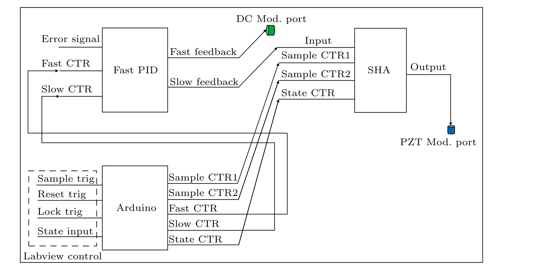
To ensure the smooth and coordinated operation of the circuit components, precise control sequencing is essential.We employ a single-chip microcomputer (Arduino Mega 2560) to generate these control sequences.The Arduino receives four initial control signals and generates five distinct control signals in the appropriate delay and order.As illustrated in Fig.2, the five output control signals comprise the fast CTR and slow CTR,triggering the fast and slow feedback loop locks respectively.The remaining three control signals are depicted in Fig.1(c), which control the offset state and the two SHAs.Among the four input control signals, the reset trig initializes the values of the five Arduino outputs; the lock trig enables the fast CTR and slow CTR in turn,and oversees the unlocking and relocking of the loops; the state input directly controls the output state CTR signal with appropriate time delay, altering the locking point after loop unlocking;and the sample trig triggers the sample CTR1 and sample CTR2 sequentially shortly after the relocking of the slow feedback loop.The four input control signals are from an NI card,which is managed through a LabVIEW program.This Lab-VIEW program can orchestrate the frequency hopping within the OPLL,together with other experimental sequences.
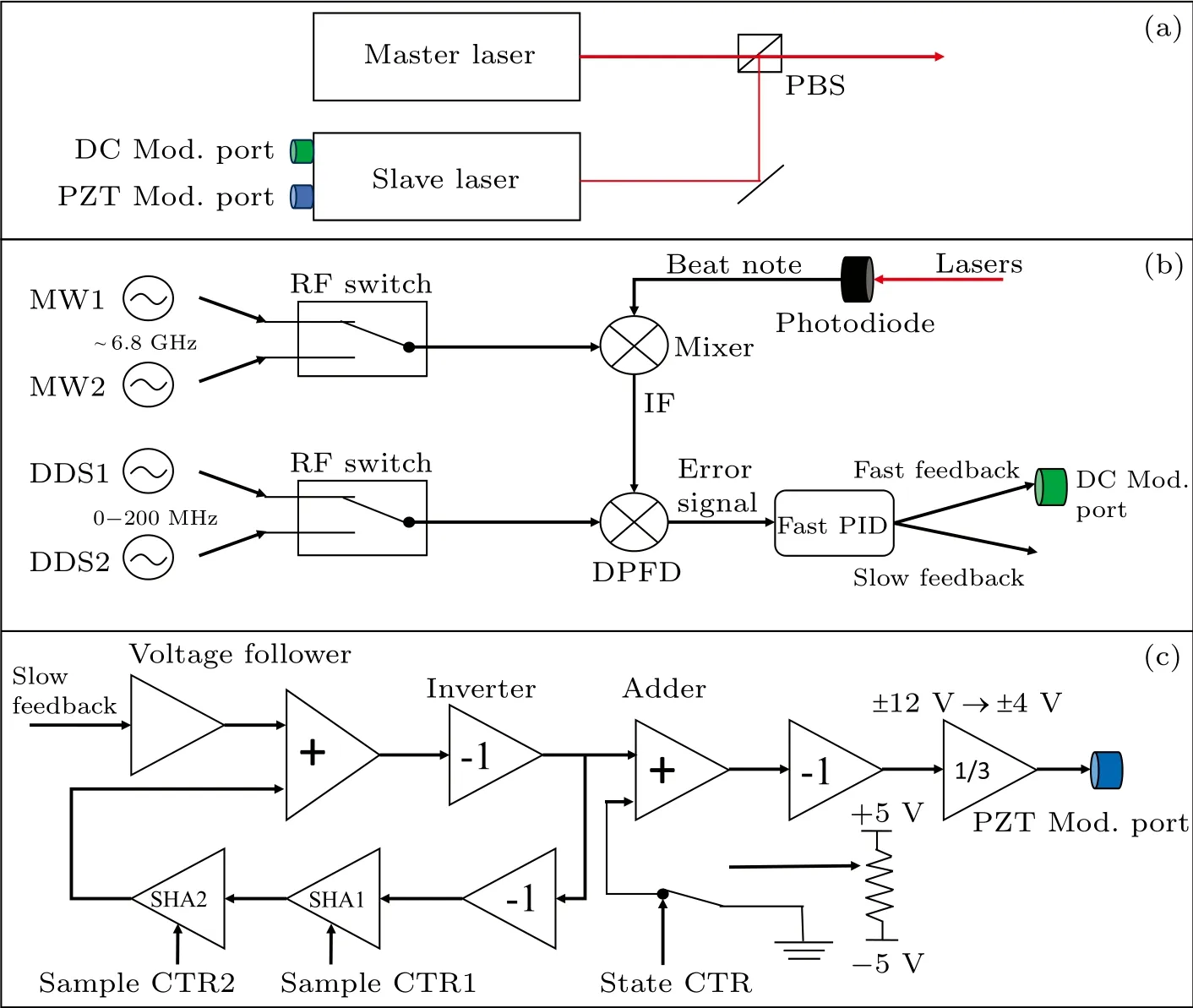
Fig.1.Diagrams of the technique.(a)The lasers in the OPLL.The beat note is generated by two laser devices and the two modulation ports of the slave laser are used for feedback ports.(b)The reference frequency and feedback circuits of the OPLL.The reference MW and RF can be selected by two RF switches.(c)The SHA circuits.The slow feedback signal from the PID adds up with the SHA output,which is then further added to a designated offset voltage,culminating in the ultimate feedback signal into the PZT Mod.port.
2.2.Performance of the technique
With the aforementioned circuits, we focus on assessing the unlock-and-then-relock process.The response performance subsequent to a lock trig signal is captured via an oscilloscope,as illustrated in Fig.3.The rising edge of the lock trig(black line)enables the unlock and relock sequence.The relock trigger is 0.4 ms delayed from the unlock trigger for the fast feedback loop, while it is 0.5 ms for the slow feedback loop.The state switch of the reference frequency and slave laser frequency occurs 0.1 ms after the unlock, as shown by the PZT Mod.line(red line).The lock action exhibits a total delay of under 0.5 ms,as shown by the error signal line(blue line),which is mainly limited by the PZT capacitance.Thanks to the presence of the SHA circuits, the slow feedback signal(green line)remains consistently close to zero,generating minor glitches rather than abrupt changes during the locking operation.This facilitates an exceedingly swift relocking process,estimated at around 50µs,accounting for the switch time of the error signal.
To control the unlock and relock of the OPLL via a transistor–transistor logic (TTL) trigger signal, we have constructed a home-made fast PID module.As shown in the insert of Fig.3,this module enables a feedback bandwidth of approximately 2 MHz,ensuring low phase noise of the Raman lasers,which is at a level of-95 dBc/Hz over the frequency range from 100 Hz to 1 MHz.This characteristic is imperative for upholding the precision of some experiments,such as gravity measurements.

Fig.3.The graph displays the unlock-and-then-relock process.The lines show the error signal(blue line)from the DPFD,the slow feedback signal(green line)and the signal into the PZT Mod.port(red line)following an unlock command initiated by a rising edge signal(black line).The inset illustrates the phase noise of the locked beat note.
3.Application in a compact atomic gravimeter
3.1.Introduction of a compact gravimeter
High-precision,compact cold atom gravimeters and gradiometers are proposed to apply across diverse fields,including geodesy,geophysical,archaeological,mineral exploration,foundational assessment of crucial infrastructure,and gravitymatched navigation.[16–19]The Ramsey–Bord´e interferometer combined with Bloch oscillations driven by a one-dimensional optical lattice is a promising scheme to construct a high precision compact gravimeter.[20,21]In the middle zone of the Ramsey–Bord´e interferometer, the optical lattice is used to coherently levitate or launch atoms to confine the atoms in a small height interval of less than 1 cm.As a result, the size no longer limits the flight time of the interferometer,which is essential to improve the measurement sensitivity.Additionally,in terms of dynamic measurement,the zero time-domain vibration transfer coefficient of the interferometer between the second and the third Raman pulses greatly suppresses the transmission of vibration,[22]leading to the high competence of this approach in vehicles with considerable vibration levels.
In the Ramsey–Bord´e atom interferometer,large-detuned Raman laser pulses are employed in the laser system to drive the stimulated Raman transition of atoms, while the nearresonance laser pulses are employed to cool the atoms, clear the atoms of the unwanted state, and probe the atomic population distribution of the interferometer output.Therefore,within this compact laser system, it becomes necessary to maintain the frequency difference of the detuning.A swift switch between the large-detuned and near-resonance states proves to be a highly effective approach.
3.2.Laser system of the atom gravimeter
Our atomic gravimeter comprises a Ramsey–Bord´e interferometer and one-dimensional optical lattice pulses.Before the interference sequence,87Rb atoms are initially cooled and trapped to create a molasses within an MOT.Subsequently,they undergo alternating interactions with Raman laser pulses andF=2 clear laser pulses.This process is used to select the initial energy state for the atom interferometer.In the middle zone of the interferometer, lattice pulses are employed to manipulate the atoms,extending the free-fall time and consequently enhancing the interference time.Finally, the ratio ofF=1 toF=2 atoms is probed as the interferometer’s output using probe beams.This time sequence is depicted in Fig.4.
The laser frequencies are illustrated in Fig.5(a).The lasers originating from theF=1 state possess constant frequencies.On the other hand, the lasers originating from theF=2 state necessitate a sweeping range of over 100 MHz during the optical molasses sequence.Subsequently,they need to be switched between the Raman lasers(yellow arrow) and the cooling/clear/probe lasers(blue and purple arrows),whose frequency interval exceeds 1 GHz.
The configuration of the laser system except for the optical lattice is illustrated in Fig.5(b).Each of the two laser sources is injected into a tapered amplifier (TA) to generate enough laser power.The master laser is frequency stabilized to the transition lineF=1→F′=0 by modulationtransfer spectroscopy(MTS).The two components of the Raman lasers are combined through a PBS, constructing a perpendicular polarization state.The laser beat signal of the slave laser and master laser is collected via a high speed photodiode, and feedback is provided to the slave laser through our frequency-hopping OPLL.The frequency interval between the repumpF=1 laser and theF=1 laser component of Raman lasers is about 1054 MHz,and is produced by the three AOMs,whose frequency shifts are 229 MHz,275 MHz,275 MHz respectively.Meanwhile, the gigahertz frequency switch of theF=2 component is achieved by frequency hopping within the OPLL.The minor frequency shifts between cooling,clear,and probe lasers are achieved directly by either sweeping or hopping the RF of a DDS, given that these frequency shifts consistently fall within the capture range of the DPFD.
Considering the frequent and rapid switching of laser pulses,often occurring within intervals as short as a few milliseconds,the OPLL must be capable of accommodating substantial hops of more than 1 GHz within 1 ms, which is achieved at 0.5 ms by our well designed frequency hopping OPLL.Also,the frequency hopping OPLL fulfills the required perpendicular polarization Raman lasers.
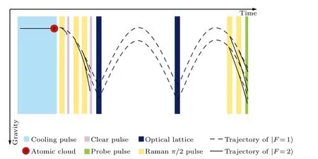
Fig.4.Time sequences of the atomic gravimeter.The valid and dashed curves are classical trajectories of atom wave packages,corresponding to F=1 and F=2 energy states respectively.The yellow bars represent the large-detuned Raman pulses.While the light blue,purple and green bars represent cooling, F =2 state clear and probe laser pulses respectively,they are near-resonance laser pulses.
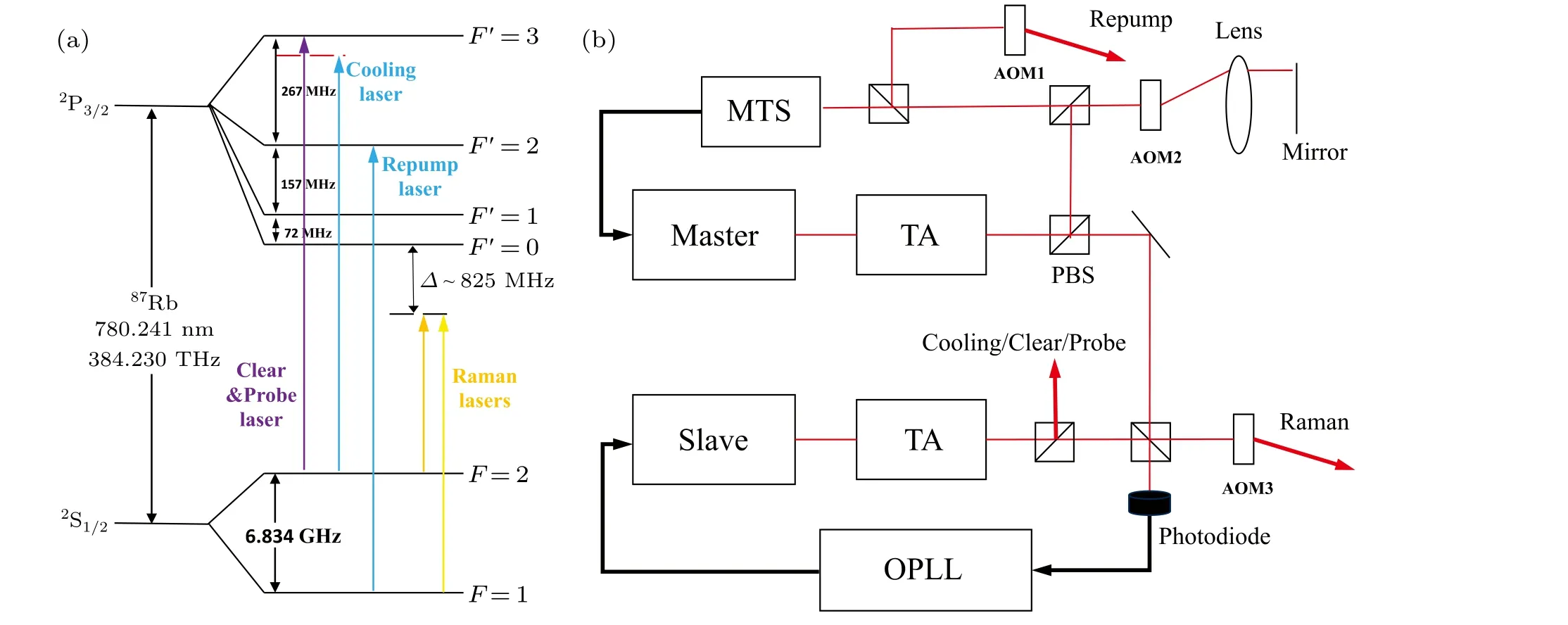
Fig.5.Laser system of the atomic gravimeter.(a)The hyperfine structure of the 87Rb D2 line,and the required laser frequencies for our atom interferometer are illustrated.(b)The configuration of the laser system.The required laser frequencies are fulfilled by two laser sources locked by the OPLL and frequency shifted by several AOMs,whose center frequency shift is 250 MHz.
3.3.Related performance of the gravimeter
We apply the frequency hopping OPLL to the gravimeter,and observe its related performance.In the cooling step, an optical molasses requires the cooling laser to be red-detuned from about 10 MHz to 160 MHz, so the DDS1 (see Fig.1)sweeps a broad frequency range in the OPLL.This broad frequency range is closely linked to the resultant molasses temperature.[10]To estimate the molasses temperature,we employed velocity selective Raman transitions.[23]The Doppler broadening of the optical molasses is firstly measured by the Doppler-sensitive Raman transition;subsequently,the frequency broadening caused by the Raman pulses is measured by the Doppler-insensitive transition.By deducting the frequency broadening from the Doppler broadening, we obtain the velocity spread of the molasses.As shown in Fig.6,in the condition of 150 ms duration of the Raman pulses,the Gaussian fitted spread is 32.5 kHz and 6.6 kHz respectively.The corresponding temperature to the velocity spread has been estimated to be 1.5µK,which is superior to the optical molasses of87Rb atoms.
Throughout one measurement cycle of about 1 s,the frequency hopping exceeding 1 GHz in the OPLL occurs 6 times as the pulses are alternately applied, which is illustrated in Fig.4.Remarkably,we achieve consistent and stable interference fringes.[24]Since the interference phase shift includes the Raman laser phase, the consistent interference fringe means the Raman lasers can maintain a continuous phase,even if the OPLL is unlocked for frequency hopping.This is due to the stable relock of OPLL, in which case only the Raman laser phase is in sync with the reference MW and RF, which can output a consistent phase of waves.
Ultimately, the frequent hopping approach integrated within the OPLL exhibits stability over an extended measurement time.We conducted a continuous gravity measurement using the atomic gravimeter, spanning a duration of approximately 40 hours.The results clearly reflect the Earth’s gravitational tides, with a short term sensitivity of about 450 µGal/The data are presented in detail in Ref.[24].This serves as a testament to the sustained efficacy of the frequency hopping OPLL scheme.
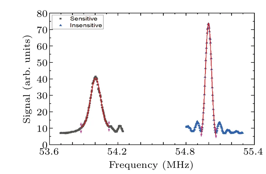
Fig.6.Raman spectrum of the Doppler sensitive (left) and insensitive(right) configuration.The red line is the Gaussian curve fit.The frequency spread is fitted to evaluate the temperature of the atomic cloud.
4.Discussion and conclusion
We demonstrate a gigahertz frequency hopping scheme of an ECDL in an OPLL.The frequency hopping is as fast as a 0.5 ms time delay.The hopping shows stable performance for more than 40 hours, with 6 frequency hops in each measurement of about 1 s.The fast and stable performance is mainly due to the feedforward switch of the PZT voltage and the SHA circuits.The SHA circuits compensate the long-time drift of the required voltage to drive the PZT in the laser, which enables a near-zero feedback voltage for the PID module.
We applied this scheme to our Ramsey–Bord´e-type atomic gravimeter,and it effectively maintains the phase continuity of Raman lasers when switching from other states back to the Raman state.The OPLL is also accompanied by the ability to sweep approximately 150 MHz at each locking point.Remarkably, we attain a 1.5 µK87Rb molasses temperature through this enhanced locking loop.
This scheme is suitable for gigahertz level frequency hopping in compact laser systems, especially when an OPLL is employed.This method can also be extended to all tunable lasers,while it fits the ECDL very well in our experiment.The hopping frequency range can theoretically extend to the entire mode-hop-free area of a tunable laser.The demonstrated methods of SHA circuits and offset voltage feedforward also have a wide range of applications in the frequency control of laser systems.Since the frequency hopping OPLL features fewer laser sources when additional frequency modulation device is not suitable for Raman lasers, it promises advancements in portable instruments.
Acknowledgments
Project supported by the National Key Research and Development Program of China (Grant Nos.2021YFA0718300 and 2021YFA1400900), the National Natural Science Foundation of China (Grant Nos.11920101004, 11934002, and 92365208),Science and Technology Major Project of Shanxi(Grant No.202101030201022), and Space Application System of China Manned Space Program.
杂志排行
Chinese Physics B的其它文章
- Unconventional photon blockade in the two-photon Jaynes–Cummings model with two-frequency cavity drivings and atom driving
- Effective dynamics for a spin-1/2 particle constrained to a curved layer with inhomogeneous thickness
- Genuine entanglement under squeezed generalized amplitude damping channels with memory
- Quantum algorithm for minimum dominating set problem with circuit design
- Protected simultaneous quantum remote state preparation scheme by weak and reversal measurements in noisy environments
- Gray code based gradient-free optimization algorithm for parameterized quantum circuit