Single exposure passive three-dimensional information reconstruction based on an ordinary imaging system
2023-12-02ShenChengDou窦申成FanLiu刘璠HuLi李虎XuRiYao姚旭日XueFengLiu刘雪峰andGuangJieZhai翟光杰
Shen-Cheng Dou(窦申成), Fan Liu(刘璠), Hu Li(李虎), Xu-Ri Yao(姚旭日),Xue-Feng Liu(刘雪峰),‡, and Guang-Jie Zhai(翟光杰)
1Key Laboratory of Electronics and Information Technology for Space Systems,National Space Science Center,Chinese Academy of Sciences,Beijing 100190,China
2University of Chinese Academy of Sciences,Beijing 100049,China
3Laboratory of Satellite Mission Operation,National Space Science Center,Chinese Academy of Sciences,Beijing 100190,China
4Center for Quantum Technology Research and Key Laboratory of Advanced Optoelectronic Quantum Architecture and Measurements(MOE),School of Physics,Beijing Institute of Technology,Beijing 100081,China
5Beijing Academy of Quantum Information Sciences,Beijing 100193,China
Keywords: passive three-dimensional imaging,single exposure,point spread function,compressed sensing
1.Introduction
Three-dimensional(3D)imaging has wide applications in many fields, such as autonomous driving, industrial production, geographic surveying, and life sciences.[1–3]Based on types of light-source and the corresponding working principles, it can be divided into active and passive imaging.Active imaging is the mainstream 3D imaging technology and includes LiDAR,3D holographic imaging,and structured light imaging.However,it cannot satisfy the imaging of low reflective and self-luminous targets,whereas passive imaging technology is not limited by specific target scenes.Various passive 3D imaging methods have already been proposed,such as multi-camera 3D imaging,[4]monocular 3D imaging based on a convolutional neural network,[5]and 3D imaging based on optical coding.[6–9]Monocular passive 3D imaging technologies have made considerable progress in recent years.However, most of them require multiple exposures[2]and codings,which makes the system relatively complex,and a large amount of computation and storage space is required for the algorithm execution.[10]This decreases the measurement speed and cannot meet requirements of real-time dynamic imaging.Thus, the exploration of an efficient, low-data volume, and simplified passive imaging method based on single exposure is currently an urgent problem to be solved.
In recent years, compressed sensing (CS)[11–15]has become a hotspot in the application of image fields.[10,16,17]CS is a signal acquisition theory that breaks the requirements of the Nyquist sampling theorem and can recover most of the original signal under subsampling conditions.With the advent of single-pixel cameras,[18]CS imaging has been researched in depth, including single-photon CS imaging,[19]CS LiDAR,[20,21]and CS imaging combined with deep learning.[22]CS has also enabled considerable progress in multi-dimensional imaging,such as spectral imaging,[23–25]3D imaging,[2,26]and high-speed video imaging.[27–29]
In terms of 3D information reconstruction,Sunet al.used illumination coding in combination with a multi-angle singlepixel detector to collect information on objects and calculated 3D information using the surface gradient method.[30]Yuanet al.proposed an efficient reconstruction algorithm based on single exposure coding full-focus clear images and depth maps.[31]Liet al.used a 3D point spread function (PSF) in optical microscopy to perform fast and accurate imaging of small samples.[32]Although the above 3D imaging schemes have achieved high image quality,limitations such as systemspecific light source dependence, non-single exposure, and multiple coding still exist.
This work proposes a 3D imaging method based on CS,which uses an ordinary two-dimensional (2D) imaging system to establish a 3D imaging method based on passive detection under the condition of single exposure.This method compresses multi-dimensional depth data into a 2D plane,the point spread function (PSF) of the system is used to reconstruct the 3D information of the target from the detected 2D image.Thus,the ordinary 2D imaging system has 3D imaging capabilities.In this work, the relationship between the PSFs of the system and the 2D intensity detection results is theoretically analyzed.Then,the reconstruction measurement matrix is constructed,and the compressive imaging algorithm is combined with 3D information reconstruction to achieve 3D information measurement without coding.Simulation and experiments have shown that this method helps to obtain 3D information under the conditions of ordinary 2D detector,and can achieve millimeter-level vertical resolution under the conditions of single exposure and passive detection.This promotes the development of 3D imaging systems towards miniaturization,simplification,and real-time dynamic imaging.
The remainder of this paper is organized as follows: Section 2 introduces the theoretical method of 3D information reconstruction based on an ordinary imaging system.In Section 3, the design of simulated PSFs is proposed and results from numerical simulations are presented.In Section 4,an experimental system set to demonstrate the passive 3D imaging effect of single exposure based on compressed sensing is reported.In this section, the experimental system is calibrated and the experimental results are discussed in detail.The main conclusions of the study are summarized in Section 5.
2.Theoretical method
An ordinary imaging system with a 3D target is shown in Fig.1.According to the basic principle of an imaging system,a target becomes a clear image at the plane that satisfies the lens imaging formula and a blurred image at the defocus state.The blurring degree of the image is related to the distance from the target to the imaging plane, which can be quantitatively described by the convolution of the original target information and the PSF of the corresponding depth.Therefore, the PSF has a linear coding effect on the target.For 3D target scenes,information from the target at multiple depths is imaged by an optical system and linearly superimposed on the detector plane to form a 2D aliased image.The intensity of every image pixel is connected with the original target information at different depths by the 3D PSFs of the system.This imaging process can be expressed by
wheretn(x′)represents the 3D target with a spatial coordinate ofx′,nis then-th depth layer of the target,Nis the total number of depth layers that need to be reconstructed,I(x) is the image intensity received by the detector with a spatial coordinate ofx,Hn(x′,x)represents the optical transmission relationship of the imaging system at then-th depth,which is the sub-measurement matrix of the current depth,PSFnis the PSF of the imaging system at then-th depth,⊗represents the convolution operation,Ex′is a matrix with the same size as one layer of the target and the element value is 1 only atx′,andℓrefers to the operation of reshaping a matrix into one row and merging different rows.

Fig.1.Single exposure 3D imaging technology based on compressed sensing.

Fig.2.Schematic of the 3D-imaging matrix relationship for single exposure under ideal conditions.The rectangular area in the upper left corner is the convolution diagram of the PSF on different target pixels.
From Eq.(2),after the PSFs are determined,the measurement matrix of the whole system is constructed via a convolution calculation.Further expanding Eq.(2)(from the perspective of pixels)can provide the diagram of the imaging system matrix.The rectangular area in the upper left corner of Fig.2 is the convolution diagram of the PSF on different target pixels.The PSF matrix is called the convolution kernel and is used to construct the current depth measurement matrix.The diffusion processes for different center pixels can be considered as the translation of the convolution kernel.According to the diffusion range (i.e., the red rectangular area at the upper left corner of Fig.2), one row of the sub-measurement matrix can be obtained.After convoluting all pixelsx′in the 3D space, multipleHncan be horizontally merged to obtain the overall measurement matrixH.Figure 2 shows the imaging relationship diagram of the system from the pixel perspective.H1,H2, andHnare the sub-measurement matrices of each depth, and they construct the overall measurement matrixHvia horizontally merging.
As can be observed from Eq.(2) and Fig.2, when the image size of each depth isQ×Q,the image size of the submeasurement matrixHn(x′,x) at that depth isQ2×Q2.Assuming a reconstructed depth layer number ofN, the overall measurement matrixHisQ2×(Q2×N)with a sampling rate of 1/N.The following equation can be obtained by digitizing the graphical description shown in Fig.2:
whereq=Q2is the total number of pixels of the image at each depth.Using the known values ofHandI,the original information of images at different depths can be obtained by solving the equations based on the CS algorithm.Thus,we can use the ordinary imaging system to obtain a 2D aliased image and reconstruct the information of 3D targets.In the CS, the object information is reconstructed by solving the following optimization problems:
where TV(t)is the total variation oft.In this work,we apply total variation minimization using the augmented Lagrangian and alternating direction algorithms(TVAL3)[33]and the sparsity of the 3D objects gradient to solve Eq.(4).
3.Simulation
We first validate the feasibility of the 3D information reconstruction method by simulation.The image size in this simulation is 64×64 pixels,and the number of depth layers to be reconstructed isN=3.Therefore,the size of the generated measurement matrixHis 4096×(4096×3).In the simulation process,we assume the condition of paraxial approximation, and the system PSF in the same depth plane has linear shift invariance.According to the properties of lens imaging and the Fresnel diffraction formula,the transfer function of the system is calculated as follows:
whereUi(xi,yi) is the intensity value at (xi,yi) of the image plane,U0(x0,y0)is the intensity value of the target at(x0,y0),λis the wavelength of the incident light,d0is the object distance,diis the image distance,P(ξ,η)is the pupil function,fis the focal length of the lens,jis the complex factor,andkis the wave number,withk=2π/λ.
The PSF of an optical system can be considered as the image when imaging a point target at a particular depth.By taking the parametersx0andy0in Eq.(5)to be zero,the quadruple integral can be simplified to a double integral
According to Eq.(6), the PSFs of the imaging system at different object distances can be obtained via numerical integration.The PSFs of the imaging system at any depth are isotropic,therefore the main elements of the measurement matrix are axisymmetric with the diagonal of the matrix,as shown in Fig.2.Using the simulated PSFs and the original images for the convolution operation,the original images at different depths are blurred to different degrees, and the 2D detection images of targets at different depths can be simulated.The linear superposition of detection images at different depths is equivalent to the single exposure effect for 3D targets.Then,the 3D information is reconstructed by using the CS algorithm TVAL3.
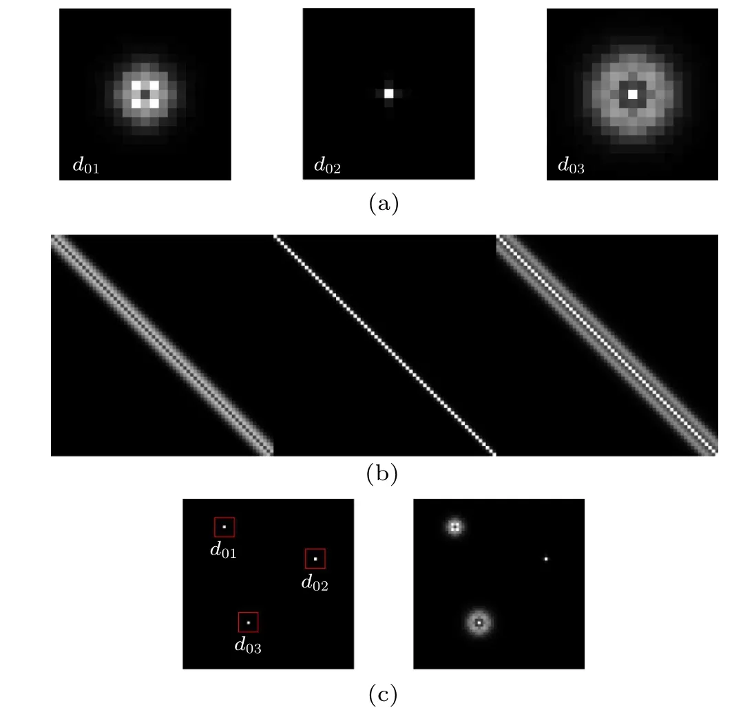
Fig.3.Simulation results of the single exposure 3D information reconstruction.(a) PSFs at different depths; (b) measurement matrix.For convenience,only part of the sub measurement matrices H1,H2,and H3 are displayed.(c)Original clear images of three depth point targets(left),and the 2D aliased image obtained by the imaging system(right).The three target imaging results are normalized individually.
Figure 3 shows the simulation results of the imaging process of several point targets at different depths.The size of the selected convolution kernel is 19×19.It is assumed that the detector can measure information from a single pixel at any depth within the pixel size of 19×19.Figure 3(a)shows the PSFs corresponding to different depths, calculated with Eq.(6).The simulation selects object distancesd01=99.6 mm,d02=100 mm,d03=100.6 mm, image distancedi= 100 mm, lens focal lengthf= 50 mm, wavelengthλ=540 nm,lens aperture is 10 mm,and pupil functionP(ξ,η)=1.Figure 3(b)shows the measurement matrix constructed according to Fig.3(a).For convenience,only parts of the sub-measurement matricesH1,H2,andH3are displayed.The left side of Fig.3(c)shows the original clear images of the point targets at different depths, and the right side shows the actual 2D imaging result of the imaging system.In the simulations,1%noise is added to the detected image.

Fig.4.Simulation results of the reconstruction of point targets at different depths.(a)–(c)Results of 3D reconstruction of simulation image on the right side of Fig.3(c)using the TVAL3 algorithm with the vertical positions of d01=99.6 mm,d02=100 mm,and d03=100.6 mm,respectively.
Figure 4 shows the 3D information reconstruction results, from which the point targets with different depths can be clearly distinguished from the 2D aliased imaging result.In this study, the peak signal-to-noise ratio (PSNR) is used to evaluate the imaging quality.For two monochrome images with a size ofm×n,the PSNR is typically defined by the mean square error(MSE):
wherezandz0are the reconstructed image and the original image, respectively, with coordinates of (i,j), and MAXIis the maximum value of the image,which is 255 in our simulation.Using Eqs.(7) and (8), the reconstructed PSNRs of the three point targets are calculated to be 137.33 db, 153.76 db,and 91.93 db, respectively.This result shows that the single exposure 3D imaging scheme based on CS can achieve clear localization and high-quality reconstruction of point targets at different depth positions.

Fig.5.Simulation results of 3D reconstructions of binary letter targets at different depths.(a)Single exposure 2D imaging result;(b)–(d)3D reconstruction results of the simulation image (a), with the vertical positions of d01 =99.6 mm, d02 =100 mm, and d03 =100.6 mm,respectively.
Figure 5 shows the simulation results of 3D reconstructions of binary letter targets at different depths.The imaging targets are the letters C, A, and S, and their distances from the imaging system ared01,d02, andd03, respectively.The PSFs are the same as those in Fig.3(a).Figure 5(a) shows the 2D aliased image obtained by the imaging system with 1%noise added.Figures 5(b)–5(d)show the reconstructed results at the three depths, and the PSNRs are 29.87 db, 41.78 db,and 28.16 db, respectively.It can be observed that for binary image targets,the reconstruction can still achieve satisfactory results.Therefore, 3D information reconstruction algorithms and schemes based on CS can achieve both high-quality positioning of point targets and high-precision reconstruction of complex images at different depths.

Fig.6.Simulation results of 3D reconstructions of grayscale letter targets with grayscale values changing linearly from top to bottom between 0 and 255: (a)2D aliased image;(b)–(d)reconstruction results at the positions of+8 mm,0 mm,and+19 mm,respectively.
To further verify the 3D imaging ability, we study the imaging effect for multi-depth and multi-level grayscale letter targets.The grayscale letters C, A, and S at depths ofd01=99.6 mm,d02=100 mm,d03=100.6 mm, are used,and the grayscale values of each letter change linearly from top to bottom between 0 and 255.The reconstruction results are shown in Fig.6.Figure 6(a) gives the 2D aliased image obtained by the simulated PSFs.Figures 6(b)–6(d) show the reconstruction results with different depths.It can be seen that the grayscale changes of the letters are accurately reconstructed.The PSNRs of the reconstructed grayscale images are 36.51 db, 42.30 db, and 34.82 db, respectively.These results confirm that the 3D imaging method depending on the ordinary imaging system has good universality,and can complete the acquisition and reconstruction of 3D information for grayscale objects without coding.

Table 1.Reconstructed PSNRs and times corresponding to PSFs of different sizes.
During the simulation,we found that the selection of the PSF sizes would affect the construction of the measurement matrix and the overall reconstruction quality.Under the condition of consistent computing resources, the selection of the PSF size would also have a certain impact on the reconstruction time.We change the size of the PSFs in Fig.3(a) and compare the corresponding imaging qualities to explore the influence of this on the reconstruction quality and to obtain the optimal PSF range.The simulation uses a PSF of 19×19 pixels to blur the original letter target, and then constructs measurement matrices with PSF sizes of 5×5 to 19×19 pixels to reconstruct the image,and studies the PSNRs and reconstruction times.The simulation data are listed in Table 1.
In Table 1,PSNR1,PSNR2,and PSNR3 characterize the reconstruction performance of targets before,on,and after the focal plane,respectively.It can be observed that within a certain range, changing the PSF size has no clear impact on the reconstruction results.Compared to the PSFs of the large area,the PSFs of the small area applied to the 3D reconstruction will degrade the PSNR of the image.This is due to the lack of edge information on the relevant PSF, resulting in a deviation between the accurate measurement matrices and those actually used.Therefore, the size of the PSFs should be as large as possible within the allowable range of the image size to include all the diffusion information.As shown in the last row of Table 1,the reconstruction time is positively correlated with the size of the PSF.Therefore,it is necessary to comprehensively consider the matching relationship between PSF size and reconstruction quality,reconstruction time and computing resources, and select the appropriate size of PSFs to find the best reconstruction scheme.
4.Experimental results and discussion
4.1.System calibration
In this section, we verify the 3D imaging scheme experimentally.According to the proposed 3D imaging principle,obtaining the measurement matrices at different depths in advance is necessary to reconstruct the 3D image information.From the above reconstruction relationship,it can be seen that the reconstruction quality of the system depends on the accuracy of the measurement matrix at different depths, which is the core of 3D information reconstruction, and its performance is determined by the PSFs at the corresponding depths.In order to obtain the most realistic experimental PSFs and to improve the performance of the experimental 3D imaging system,we first obtained the most realistic 3D PSFs of the system through optical calibration to build the measurement matrix.It should be emphasized that the calibration process is performed before imaging,and therefore will not affect the imaging speed performance of this single exposure 3D imaging method.
The calibration system is shown in Fig.7.It consists of a charge-coupled device(CCD,GEV-B1620M-TC000)with a pixel size of 7.45µm, an optical combination lens with focal length of 41 mm and an effective aperture of 3.2 mm,an LCD display,a millimeter-level electric displacement platform,and a computer.The PSF at a particular distance can be obtained by imaging a single pixel highlight point target with the imaging system.In the calibration process, the LCD display exhibits a white single-pixel highlight to generate a point target with a size of 78µm,and it forms an image on the CCD with a size of approximately 16×16 pixels when the LCD is on the focal plane of the imaging system.In the calibration and subsequent imaging process, 8×8 CCD pixels are combined into one pixel to generate a more ideal PSF.During the experimental calibration process,we moved the highlight point target on the electric displacement platform in 1 mm step within the range of 27–71 mm.When it reaches the specified position, the exposure of the point target at the current depth is taken to obtain the speckle image at that depth, which is the experimental PSF of the system at the current depth.To facilitate comparison,the focal plane position is defined as 0 mm,and the direction from the focal plane away from the imaging system is a positive distance,while the opposite direction is a negative distance.

Fig.8.Calibration results of PSFs,at positions+8 mm(a),0 mm(b),and+19 mm(c).
Figure 8 shows the PSFs calibration results of the point target at three different depths of 5 mm, 41 mm, and 60 mm,and at the relative positions of+8 mm, 0 mm, and+19 mm,respectively.The PSFs are used as the convolution kernel to construct the measurement matrix for each depth.We notice that the measured PSFs are not uniformly diffused.There are two main reasons for this.One is that the point target displayed by the LCD is not exactly on the optical axis.The other is that we cannot strictly ensure that the motion direction of the electric displacement platform and the imaging system are coaxial.The combined effect will affect the quality of the measurement matrix to a certain extent.
To investigate the performance of the real imaging system, we perform the simulation described in Section 3 again with the calibrated PSFs.According to the calibration data,the measurement matrix is constructed using a PSF with a size of 19×19 pixels.The 3D targets are the letters C,A,and S located at+8 mm,0 mm,and+19 mm,respectively.Figure 9(a)shows the simulated 2D imaging result.The 3D reconstruction results are shown in Figs.9(b)–9(d), from which we can see that the 3D target information at different depths can be clearly reconstructed into three planes.The PSNRs of the reconstructed images are 30.75 db, 41.25 db, and 26.02 db, respectively.In the practical experiments,ideal PSFs cannot be easily obtained.However,the 3D reconstruction results of the targets are not significantly affected by this.This shows that the measurement matrix constructed by calibrated PSFs satisfies the requirement of CS theory and can be used to achieve high-quality 3D information reconstruction.

Fig.9.Reconstruction results of binary letter targets using calibrated PSFs with depths of+8 mm, 0 mm, and+19 mm: (a)2D aliased image,(b)–(d)reconstruction results.
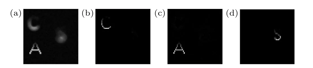
Fig.10.Reconstruction results of grayscale letter targets using calibrated PSFs with depths of+8 mm,0 mm,and+19 mm:(a)2D aliased image,(b)–(d)reconstruction results.
In order to reflect the imaging ability of the experimental system for grayscale targets,we use the experimental PSFs shown in Fig.8 to simulate the imaging for grayscale letter targets.The grayscale letters C,A,and S are located at depths of +8 mm, 0 mm, and +19 mm, respectively.The reconstruction results are shown in Fig.10.Figure 10(a)is the 2D aliased image obtained by using the experimental PSFs.Figures 10(b)–10(d) are the reconstruction results, of which the PSNRs are 35.29 db, 44.71 db, and 31.86 db, respectively.These results confirm that the 3D imaging method can have good reconstruction performance for complex grayscale objects in the real experiment.
4.2.Experiments
After the calibration of the system PSFs, the imaging of actual objects is performed.The experimental imaging system is shown in Fig.11.We also use the LCD display to show images as the objects to be tested to ensure that the imaged objects are accurately aligned with the calibration position.During the experiment, the letters C, A, and S are displayed on the LCD display at different depths, and then exposed by a CCD to obtain a 2D aliased image of the letter targets at multiple depths.There are two cases of focus position in this study,which are discussed as follows: The condition wherein the defocused objects are on the same side of the focal plane is defined as a unidirectional defocus state, and the condition wherein the defocused objects are on opposite sides of the focal plane is defined as a bidirectional defocus state.We conducted the four experiments given in Table 2 for different defocus conditions and position states.

Table 2.Four different experimental defocus states.

Fig.11.Experimental imaging system.
Figure 12 shows the results of experiments 1 and 2,and the 2D imaging results are shown in Figs.12(a) and 12(e).From the reconstruction results in Figs.12(b)–12(d)and Figs.12(f)–12(h),it can be observed that the 3D images were reconstructed using the CS algorithm, which can clearly separate letter targets at different depths and achieve almost fullfocus reconstruction.This demonstrates that our proposed 3D imaging system and reconstruction method can achieve very satisfactory imaging performance in both unidirectional and bidirectional non-equidistant defocus states.

Fig.12.The blurred images and reconstruction results of experiments 1 and 2.[(a),(e)]Images obtained in experiments 1 and 2.[(b)–(d),(f)–(h)]Reconstruction results.In experiment 1,the positions of the letters C,A,and S are+8 mm, 0 mm, and+19 mm, respectively.In experiment 2,the positions are-11 mm,0 mm,and+19 mm,respectively.
Figure 13 shows the 3D reconstruction results under unidirectional equidistant defocus of experiment 3.The fixed letter C is located at 0 mm,and distances of C–A and A–S vary equally from+3 mm to+8 mm.The first column in the figure is the 2D aliased images obtained by a single exposure, and the second to fourth columns correspond to the reconstruction results of different depth information.It can be seen that the reconstruction quality improves as the distance between adjacent depths increases.When the distance between adjacent depths is 3 mm, the reconstruction is unideal.At a distance between adjacent depths of 4 mm,the 3D imaging method described in this study can achieve excellent visual reconstruction results, confirming that its vertical resolution can reach millimeter level in the unidirectional equidistant defocus state and it has strong imaging ability.

Fig.13.Reconstructed images of experiments in the unidirectional equidistant defocus state of experiment 3.The distances of C–A and A–S vary equally from+3 mm to+8 mm,respectively.
Experiment 4 verified the imaging ability under the bidirectional equidistant defocus state.The 2D imaging results are revealed in Figs.14(a) and 14(e), with the defocus distances of±5 mm and±14 mm,respectively.The 3D reconstruction results are shown in Figs.14(b)–14(d) and Figs.14(f)–14(h).When the defocus distance is±5 mm, the reconstructed 3D image quality is unideal.In the state of short-spacing bidirectional equidistant defocus,there is crosstalk in the PSFs at different depths, which hinders the information separation of 3D targets at different depths.When the defocus distance is increased to±14 mm,the reconstruction can complete the 3D information separation of the targets at different depths.From this experiment, it can be concluded that the imaging system can achieve a vertical resolution of 14 mm in the bidirectional equidistant defocus state.

Fig.14.Reconstructed images of experiments in the bidirectional equidistant defocus state: [(a), (e)] 2D images acquired in experiment 4,[(b)–(d),(f)–(h)]reconstruction results.The positions of the letter A in the two experiments are both 0 mm,while those of the letters C and S in the two rows are±5 mm and±14 mm,respectively.
4.3.Average correlation coefficient and vertical resolution
Figure 15 shows the PSFs at depths of 0 mm,±5 mm,and±14 mm.We can see that in the state of bidirectional equidistant defocus,the PSFs of the optical system exhibit similarity at symmetrical positions relative to the focal plane, as shown in Figs.15(a)and 15(c)or Figs.15(d)and 15(f).In this situation,the characteristic difference between the PSFs is unclear,which significantly affects the performance of the measurement matrix and makes it hard to accurately complete the reconstruction of 3D information at different depths.This is an important reason for the difficulty of 3D reconstruction in the bidirectional equidistant defocus state.
Additionally, it can be observed from Fig.15 that there are differences in the radii of these PSFs at different depths.The reconstruction results in Fig.14 show that in the bidirectional equidistant defocus state, the larger the PSF radius difference,the greater the reconstruction accuracy.
In this work,we found that the similarity of PSFs between different depths affects the performance of 3D information reconstruction, and this similarity can be measured using the correlation coefficientρ(A,B),
where cov(A,B)is the covariance of the matricesAandB,andσAandσBare the standard deviations of the matricesAandB, respectively.Since this work involves 3D reconstruction of multiple depth information,there will be multiple correlation coefficients between PSFs.We use the average correlation coefficient(ACC)between PSFs at multiple depths to measure the performance of the 3D information reconstruction system.Calculating the correlation between PSFs at different depths is equivalent to the traditional method of directly examining the correlation of the measurement matrix, as the measurement matrix used for 3D information reconstruction is generated by PSFs at different depths.This method significantly reduces the computational complexity as the scale of the PSF is much less than that of the measurement matrix.

Fig.15.PSFs under the bidirectional equidistant defocus state at different depths: [(a)–(c)]PSFs at depths of-5 mm,0 mm,and+5 mm,[(d)–(f)]PSFs at depths of-14 mm,0 mm,and 14 mm.
Table 3 shows the calculation of the ACC of PSFs between three different depths in the four experiments, which are in good agreement with the reconstruction results given above.For the same defocus states,combined with the experimental reconstruction results,we found that a larger ACC will degrade the reconstruction quality,which further demonstrates that the ACC can be used to evaluate the overall ability of the system to reconstruct 3D information.
In the experiment, we investigated the relationship between the ACC and the distance of adjacent depths in both unidirectional and bidirectional equidistant defocus states.The results are shown in Fig.16, in which the star points are the calculated results,and the blue lines are the fitting curves.As can be analyzed, under the conditions of unidirectional and bidirectional equidistant defocus, the ACC of the system exhibits a monotonic characteristic as the distance between adjacent depths increases.Combining the 3D reconstruction results in Figs.13 and 14, it can be concluded that the reconstruction performance of the system becomes better as the ACC between the PSFs of different target depths decreases.

Fig.16.The variation relationship between the average correlation coefficient (ACC) of PSFs and the distance of adjacent depths in the equidistant defocus state: (a) unidirectional equidistant defocus state,(b)bidirectional equidistant defocus state.
From the reconstruction results, we observe that in the bidirectional equidistant defocus state,the ideal reconstruction effect cannot be achieved until the defocus distance reaches about 14 mm.At this time, the ACC of the PSFs is 0.51.However, in the unidirectional equidistant defocus state, the vertical resolution of the system can reach 4 mm, with the ACC of the PSFs being 0.67.Based on the above experimental comparison, it can be estimated that in the bidirectional equidistant defocus state, the ideal reconstruction quality requires ACC less than 0.5,while in the unidirectional equidistant defocus state,the demand is relaxed to less than 0.7.From the above results, it can be seen that the imaging system in this work can achieve excellent imaging performance under non-equidistant, unidirectional equidistant, and long-spacing bidirectional equidistant defocus states; and the performance needs to be further improved under the condition of shortspacing bidirectional equidistant defocus state.
5.Conclusion
This work proposes a single exposure 3D information reconstruction method based on CS theory, which can achieve passive localization and high-quality reconstruction of 3D target information from intensity aliased information measured by an ordinary 2D imaging system without coding.We have verified the effectiveness of the 3D imaging scheme through simulations and experiments.This method combines the compression sampling ability of CS and the sparse characteristics of 3D targets, utilizes the system measurement matrix generated by calibrated PSFs and the optimization algorithm proposed in this work to achieve millimeter-level vertical resolution.
It is generally considered that a 2D image obtained by an ordinary imaging system without a coding template will lose its depth information.However, the method proposed in this study can reconstruct the blurred 2D aliased image to nearly a full-focus state and separate the 3D target into different depths.Compared with the existing 3D imaging systems, the proposed method does not rely on the active light source and frequently used coding mask,and simplifies the traditional 3D detection process from multiple coding sampling to a single exposure sampling without coding.Therefore,this method overcomes the limitations of complex equipment,light source dependence,active coding,and the slow imaging speed of traditional 3D imaging systems,and promotes the development of 3D imaging systems toward miniaturization, simplification, and real-time dynamic imaging.The needed optical system has no special restriction on application scenarios or imaging distances.We believe it could play an important role in many related applications such as microscopic imaging or long-distance remote sensing.
The vertical resolution of our method is highly related to the 3D PSFs of the optical system, which is decided by the aperture design,aperture size,and focal length.The ordinary simple optical apertures may not be the best choice because of the high similarity between PSFs of adjacent depths.To further improve the vertical resolution,our future work will focus on optimizing the aperture of the imaging system to reduce the ACC of the PSFs and seeking more effective algorithms,such as utilizing deep learning technology.Another issue to be resolved is that as the reconstructed depth number increases,the sampling rate decreases,and the performance of imaging quality and reconstruction speed will be affected.Therefore, further optimization of the reconstruction algorithm can be performed, for example, utilizing 3D information correlation of continuous targets to increase the data sparsity and developing parallel block reconstruction algorithm to reduce the reconstruction complexity.
Acknowledgments
Project supported by the National Key Research and Development Program of China (Grant No.2018YFB0504302)and Beijing Institute of Technology Research Fund Program for Young Scholars(Grant No.202122012).
猜你喜欢
杂志排行

Chinese Physics B的其它文章
- Optimal zero-crossing group selection method of the absolute gravimeter based on improved auto-regressive moving average model
- Deterministic remote preparation of multi-qubit equatorial states through dissipative channels
- Direct measurement of nonlocal quantum states without approximation
- Fast and perfect state transfer in superconducting circuit with tunable coupler
- A discrete Boltzmann model with symmetric velocity discretization for compressible flow
- Dynamic modelling and chaos control for a thin plate oscillator using Bubnov–Galerkin integral method