Rucklidge-based memristive chaotic system:Dynamic analysis and image encryption
2023-11-02CanLingJian蹇璨岭ZeAnTian田泽安BoLiang梁波ChenYangHu胡晨阳QiaoWang王桥andJingXiChen陈靖翕
Can-Ling Jian(蹇璨岭), Ze-An Tian(田泽安)2,,†, Bo Liang(梁波), Chen-Yang Hu(胡晨阳),Qiao Wang(王桥),3, and Jing-Xi Chen(陈靖翕)
1College of Big Data and Information Engineering,Guizhou University,Guiyang 550025,China
2College of Computer Science and Electronic Engineering,Hunan University,Changsha 410082,China
3College of Mathematics and Big Data,Guizhou Education University,Guiyang 550018,China
4College of Mechanical Engineering,Guizhou University,Guiyang 550025,China
Keywords: chaotic system,memristor,intermittent chaos,multi-transient behavior,image encryption
1.Introduction
Since the meteorologist Lorenz discovered the first chaotic system from the weather model in 1963,[1]a large number of scholars began to pay attention to and study the chaotic phenomenon.With the deepening of research,a quantity of chaotic systems have been discovered,such as R¨ossler system,[2]Chen system,[3]L¨u system,[4]Liu system,[5]and Chua system.[6]In 1971, Chua predicted that in addition to resistance, capacitance, and inductance, there should be a passive component for connecting charge and magnetic flux,and named it memristor.[7]Because of its special nature, the hypothesis has been widely concerned and studied by researchers since it was proposed.However, it was not until 2008 that HP Labs made a solid-state memristor,[8]which marks that the research on memristors has officially changed from theory to practice.With the deepening of the research on memristors,[9,10]the special nonlinearity and nonvolatility of memristors have made them widely used in chaos,[11-13]neural networks,[14-20]secure communication,[21,22]memory,[23]neurons,[24]and chaotic oscillators.[25,26]
More and more researchers have found that adding memristors to chaotic circuits will greatly increase the complexity of the system and cause some other behaviors in the chaotic system.For example, a tri-value memristor is added to a chaotic system to make it a hyperchaotic system with hidden and coexisting attractors.[27]Baoet al.obtained hyperchaotic phenomena by paralleling two memristors and the system has extreme multistability,[28]replacing diodes in Chua oscillators with memristors yields more complex dynamic behavior,[29]the introduction of memristors into a three-dimensional (3D)chaotic system produces extreme multistability.[30]
Changing the parameters of a chaotic system can obtain different attractors, and the number of attractors can reflect the complexity of the system to a certain extent.By modifying the control parameters, the system can obtain six different shapes of attractors.[31]In a memristor chaotic circuit,by modifying four system parameters, 15 types of attractors can be obtained.[32]There are also 12 different attractors that can be obtained by modifying only one parameter, including 5 chaotic attractors and 7 periodic attractors.[33]By adjusting one parameter, various attractors can be obtained, which is more conducive to the application of the system in engineering.
Transient behavior refers to the time evolution of a chaotic system before reaching a stable state.Because it can be applied in multiple fields, studying the transient behavior of a chaotic system is more instructive for practical applications.[34]However, most chaotic systems have very few transient behaviors, typically only periodic to chaotic transitions,[35,36]or transitions from chaos to periodicity.[37]Although a memristive chaotic system with four transient behaviors has recently been reported,[34]and scholars have discovered systems with two transient behaviors coexisting,[38]as well as some other special transient behaviors,[39-41]such systems are still rare.Due to its excellent characteristics,it is necessary to study systems with multiple transient behaviors.
Due to the special chaotic sequence and high complexity, chaotic systems are often used in the field of image encryption.[42-46]However, there are few reports on the application of chaotic systems with multiple transient behaviors,so it is necessary to apply systems to the field of image encryption.
In this paper, a voltage-controlled memristor is introduced into the Rucklidge chaotic system,[47]and a new fourdimensional(4D)memristive chaotic system is obtained.The second section mainly introduces the memristor module and system model.Section 3 analyzes the dynamic and transient behavior of the system using methods such as degree of dissipation, bifurcation diagram, and Lyapunov exponent spectra.Section 4 describes the spectral entropy (SE) and C0 complexity[48]of the system.In Section 5, the chaotic system is implemented in the circuit.In Section 6,the application of the system in the field of image encryption is introduced in detail.Section 7 is a summary of the article.
2.System description
A voltage-controlled memristor is used in the document,[49]and its equation is as follows:
whereiandvrepresent the current and voltage across the memristor connection,andA,B,d,e,andfare constants.The Rucklidge chaotic system consists of the following nonlinear self-made ordinary differential equations
wherex,y,zare the state variables of the system,andk,lare constants.First,we introduce the state equation of the memristor into the system 2,then replaceyzterm in system 2 with the outputyW(w)of the memristor and modifyy2to the absolute value ofy.Finally, by modifying the Rucklidge chaotic system to obtain a chaotic system based on memristor,the new 4D memristive chaotic system proposed in this paper is described as follows:
whereW(w)=5w2-3.2,x,y,z,andware the state variables of the system,anda,b,andcare constants.Choosing this parameter can satisfy the characteristics of memristor and make the system get better chaotic characteristics.The equilibrium point of the system can be obtained by setting the following equation:
Obviously, the system has only one equilibrium point O(0,0,0,0),and the Jacobian matrix of the system at this equilibrium point can be obtained as
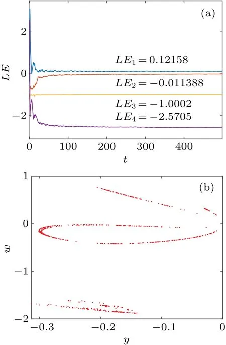
Fig.1.The Lyapunov exponent diagram and the Poincar´e section diagram of the y-w plane of the system (3) at a=2.14, b=-0.2, and c=1.75 with initial values of(1,1,0,1).(a)Lyapunov exponent diagram and(b)the Poincar´e section of the y-w plane.
The characteristic equation corresponding toJPat equilibrium is
wheren1,n2,n3,andn4are shown below:
Takinga=2.14,b=-0.2,andc=1.75 into Eq.(6),the eigenvalue of the system is obtained as follows:λ1=-0.5,λ2=1.4588,λ3=-3.5988, andλ4=-1.The eigenvalues obtained from this equilibrium point are 3 negative roots and 1 positive root, which means that this equilibrium point is an unstable equilibrium point.[50]
With the parametersa=2.14,b=-0.2,andc=1.75 set,the initial value is(1,1,0,1).Set the time step toh=0.01,and the simulation time to 5000 seconds.Use the ode45 solver to obtain a Poincar´e section of the system(3)on they-wplane,as shown in Fig.1(a).The diagram contains many scattered points, with the trajectory of the points being dense and not forming a closed curve.At this time, the Lyapunov exponents of the system areLE1=0.12158,LE2=-0.011388,LE3=-1.0002,andLE4=-2.5705,as shown in Fig.1(b).
The simulated two-dimensional (2D) and threedimensional (3D) phase diagrams obtained under the same conditions are shown in Figs.2 and 3.
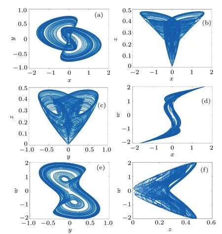
Fig.2.The 2D planar phase diagram of system(3)at a=2.14, b=-0.2,and c=1.75 with initial values of(1,1,0,1).(a)x-y plane;(b)x-z plane;(c)y-z plane;(d)x-w plane;(e)y-w plane;and(f)z-w plane.
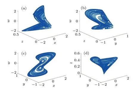
Fig.3.The 3D phase plane of the system (3) at a=2.14, b=-0.2, and c=1.75 with initial values of(1,1,0,1).(a)x-z-w;(b)y-z-w;(c)x-y-w;and(d)x-y-z.
3.Analysis of system dynamic characteristics
This section delves into a comprehensive numerical analysis of the system’s dynamic behavior.We explore the nonlinear dynamics through various perspectives, including Lyapunov exponent spectra, bifurcation diagram, phase diagram,and time domain waveform diagram.Notably,the simulation results presented in this section were obtained using the ode45 solver in MATLAB R2018b.
3.1.Degree of dissipation
The dissipation degree of system(3)can be obtained from the following dissipation calculation formula:
By solving Eq.(8),it is obtained that whena >0.994,div(v)<0,the system is always a dissipative system.In this article,we discuss that under the condition of initial values of(1,1,0,1),anda=2.14,div(v)<0,indicating that the system(3)is dissipative,the phase space volumeV0will contract to the volume elementV(t)=V0e-(a+1.5)twithin timet.
3.2.The effect of a single parameter on the attractor
Figure 4 shows the Lyapunov exponent spectra and bifurcation diagram withbparameters ranging from-0.5 to 5.5 whena=2.14 andc=1.75.From Fig.4(a), it can be seen that whenb ∈(-0.5,-0.35), the system presents a period doubling, and then becomes chaos.Whenb ∈(-0.35,1.07), the system mainly exhibits a chaotic state, but at some points it exhibits quasi-periodic or limit cycles as thebparameter increases.Whenb ∈(1.08,1.96),the system changes from periodic to weak chaos and eventually becomes chaotic,and there will be some values within this interval that are in a single periodic state.Whenb ∈(1.96, 2.16), the system becomes periodic again.Asbcontinues to increase, the system will again become chaotic, which will continue untilb=2.93 when the system enters a periodic or quasi-periodic state.Whenb ∈(3.01,5.5),in this interval,the system is very sensitive to the transformation of thebparameter.A small change in thebparameter may produce different attractors and may switch back and forth between chaos,periodicity,and quasi-periodicity.Specifically,the system is in a chaotic state over a large range,but on some individual values,the system is in a quasi-periodic or periodic state.From the bifurcation diagram,we can see that the corresponding Lyapunov exponent is greater than 0 when the bifurcation diagram is chaotic,and 0 when the bifurcation diagram is periodic.From the diagram,we can see that the Lyapunov exponent spectra can well correspond to the bifurcation diagram,indicating that the system has good chaotic characteristics.
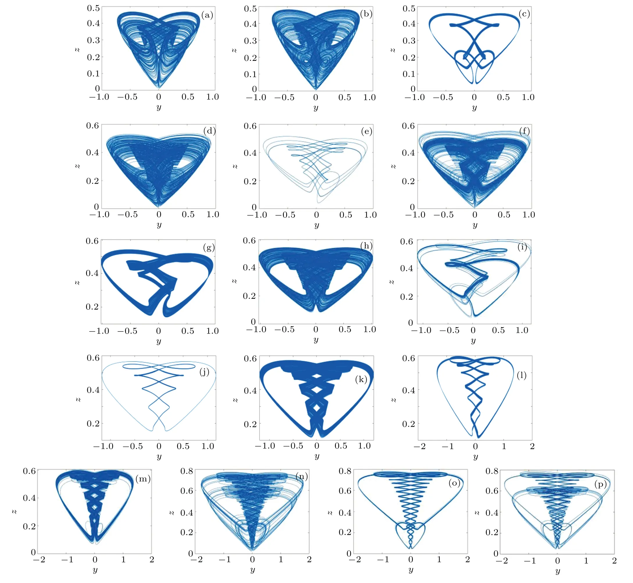
Fig.5.When the parameters a=2.14,c=1.75,and the initial value is(1,1,0,1),different b parameters produce different shaped attractors: (a)b=0.35;(b)b=-0.2; (c)b=0.174; (d)b=0.42; (e)b=0.6; (f)b=0.66; (g)b=1.12; (h)b=1.16; (i)b=1.53; (j)b=2.05; (k)b=2.18; (l)b=3.00; (m)b=3.03;(n)b=4.15;(o)b=4.38;and(p)b=4.4.
Figure 5 and Table 1 show some typical attractors and corresponding Lyapunov exponents spectra and system states as thebparameter increases.
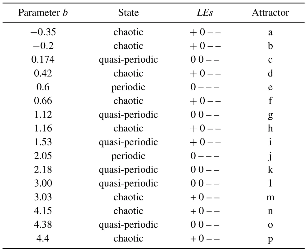
Table 1.When the parameter a=2.14, c=1.75, and the initial value is (1, 1, 0, 1), the corresponding state and attractor shape of different parameter b.
3.3.Transient behavior
Transient behavior is a special phenomenon in chaotic systems, which refers to a fixed initial condition in which a signal exhibits a chaotic or quasi-periodic state for a certain period of time,and then transitions to a different system state.Another type of phenomenon is the alternating repetition of chaos and periodicity in a certain time dimension, which is called intermittent chaos.[51]In this section, set the parametersa=2.14,c=1.75, and the initial values to (1, 1, 0, 1),the simulation step size to 0.01,and the simulation time to(0,5000 s).Use phase diagrams and time domain waveform diagrams to analyze the different transient systems obtained by modifying the parameterb.
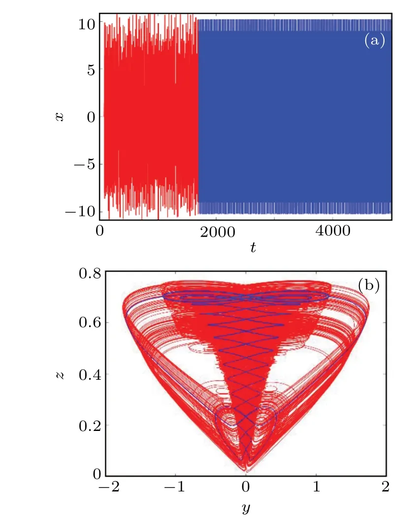
Fig.6.Waveform diagram and phase diagram at b=3.948: (a)waveform diagram with time varying x at t ∈(0,5000)s,where the red part is t ∈(0, 1684) s and the blue part is t ∈(1684, 5000) s; and (b) y-z plane phase diagram.
3.3.1.Transient type I
In the case of parameterb= 3.948, the time domain waveform and the phase diagram of theyzplane of the variablexvarying with time are studied.As shown in Fig.6,whent ∈(0, 1684 s), the overall performance of thextime domain waveform is disordered,so the system presents a chaotic state.Whent ∈(1684, 5000 s), the system changes from a chaotic state to a quasi-periodic state.Therefore, the system has a transition behavior from chaos to periodicity.
3.3.2.Transient type II
Set the parameterb=4.03 and analyze the time domain waveform of the variablexand the phase diagram of theyzplane.As shown in Fig.7(a), it intuitively reflects that the motion state of the system alternates between chaos and periodicity,resulting in significant intermittent chaos.The system changes from the initial chaotic state to a periodic state, then switches according to chaos, periodicity, and chaos, and finally maintains a periodic state Whent ∈(0,566.5)s∪(1063,1242) s∪(1751, 2480) s, the time domain waveform ofxshows a chaotic state.Within this interval, the system (3) is in a chaotic state, and the topological structure of the chaotic state attractor is the same,as shown in the red part of Fig.7(b).Whent ∈(566.5, 1063) s∪(1063, 1242) s∪(2480, 5000) s,the system(3)is in a quasi-periodic state,with the same topological structure of its attractors,as shown in the blue portion of Fig.7(b).Therefore, the system has the characteristic of intermittent chaos.
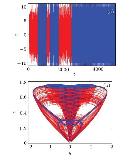
Fig.7.Waveform diagram and phase diagram at b=4.03: (a) waveform diagram with time varying x at t ∈(0,5000)s,wherein the red part is t ∈(566.5,1063)s ∪(1063,1242)s ∪(2480,5000)s,and the blue part is t ∈(0566.5)s ∪(1063,1242)s ∪(1751,2480)s;and(b)the y-z plane phase diagram corresponding to the waveform diagram.
3.3.3.Transient type III
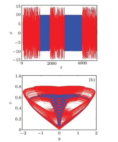
Fig.8.Waveform diagram and phase diagram at b=4.83: (a) waveform diagram with time varying x at t ∈(0,5000)s,wherein the red part is t ∈(0,1228s)∪(1864,2868)s ∪(3980,5000)s,and the blue part is t ∈(1228,1846)s ∪(2868,3980)s;and(b)the y-z plane phase diagram corresponding to the waveform diagram.
When parameterb= 4.83, the system is also intermittent chaos, and the time domain waveform ofxis shown in Fig.8(a).Whent ∈(0, 1228) s∪(1864, 2868) s∪(3980,5000)s,the system is in a chaotic state,and its phase diagram is shown in red in Fig.8(b).Whent ∈(1228,1846)s∪(2868,3980) s, the system exhibits a quasi-periodic state, and the phase diagram is shown in the blue portion of Fig.8(b).Unlike type 2,the periodic attractor of a system is different,and the system will eventually remain chaotic after a period of intermittent chaos.
3.3.4.Transient type IV
Set the parameterb= 1.53 to obtain the time domain waveform ofxand the phase diagram of they-zplane,as shown in Fig.9.Whent ∈(155, 1579) s∪(1680,2404) s∪(2979, 4048) s, the system behaves as a quasiperiodic, as shown in the blue portion of Fig.9(b).Whent ∈(1579, 1680)∪(2404, 2979) s∪(4038, 4253) s∪(4701,4048)s,the system exhibits a chaotic state,and its phase diagram is shown in the red portion of Fig.9(b).Whent ∈(4253,4701) s∪(4808, 5000) s, the system exhibits another quasiperiodic state,as shown in the black portion of Fig.9(b).The whole system presents intermittent chaos.It is worth mentioning that the two quasi-periodic states present a symmetric result, as shown in Fig.9(c).The system as a whole exhibits a state in which quasi-periodic and chaotic systems are transformed into another quasi-periodic attractor twice.
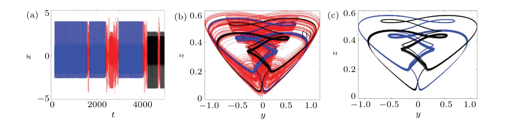
Fig.9.Waveform diagram and phase diagram at b=1.53: (a)waveform diagram with time varying x at t ∈(0,5000)s,wherein the red part is t ∈(2404,2979)s ∪(4038,4253)s,the blue part is t ∈(0,2404)s ∪(2979,4038)s,and the black part is t ∈(4253,5000)s;(b)the y-z plane phase diagram corresponding to the waveform diagram;and(c)phase diagram of two periodic attractors.
3.3.5.Transient type V
Atb= 0.401, the time domain waveform and phase diagram of systemxare made as shown in Fig.10.Att ∈(0,1253)s∪(1706,1875)s∪(2297,2699)s,the time domain waveform is chaotic,and the system exhibits a chaotic state,as shown in the red portion of Fig.10(b).Whent ∈(1253,1706)s∪(1875,2297)s,the system is in a quasi-periodic state,and the phase diagram is shown in the blue portion of Fig.10(b).Whent ∈(2297, 5000) s, the system exhibits another quasi-periodic state,as shown in the black portion of Fig.10(b).Like the two-cycle quasi-periodic attractors of type 4, there is also a symmetry between the two quasi-periodic attractors under this parameter,as shown in Fig.10(c).In the case ofb=0.401,the overall behavior of the system is chaos followed by periodicity, then switching between each other twice, and finally entering another quasi-periodic dynamic behavior.

Fig.10.The waveform and phase diagram at b=0.401:(a)the waveform of x changing over time at t ∈(0,5000)s,where the red part is t ∈(0,1253)s ∪(1706,1875)s ∪(2297,2699)s,the blue part is t ∈(1253,1706)s ∪(1875,2297)s,and the black part is t ∈(2297,5000)s;and(b)y-z plane phase diagram corresponding to waveform diagram.
4.Complexity analysis
Complexity has always been an important indicator in chaotic systems,because in the field of encryption,the higher the complexity, the more secure the system.In this section,we discuss the changes in the complexity of systems witha=2.14,b=-0.2,andc ∈(0,5.5)and initial values of(1,1,0,1)through SE and C0.
SE based on discrete Fourier transform is a measure of the complexity of a chaotic system.The larger the value of SE,the stronger the randomness of the chaotic system.When such a system is used for encryption, information security is higher.The C0 algorithm is based on fast Fourier transform,and both algorithms can be used to describe the complexity of chaotic systems.The variation of SE and C0 values with parametercis shown in Fig.11.Both SE and C0 have the same trend of change, which precisely indicates that both SE and C0 complexity can be used to describe the characteristics of chaotic systems.The maximum values of the chaotic systems SE and C0 proposed in this paper are 0.8543 and 0.7591, respectively, which indicates that the complexity of the system is very high,[52,53]and the high complexity also brings higher security for the practical application of chaotic systems,which is of great significance for the practical application of chaotic systems in the encryption field.
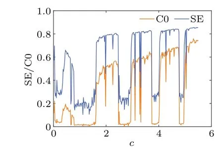
Fig.11.SE/C0 complexity of c ∈(0,5.5)systems.
5.Circuit implementation
In order to further explore system dynamics,corresponding electronic circuits can be designed, which has important physical significance for the application of chaos theory.This article compares the state differential equation with the actual circuit state differential equation to determine the total parameters of the system,making it possible to use fewer electronic components in the design of actual circuits.
The circuit system in this section is designed in Multisim,where the inverse circuit,integrator circuit,and memristor are converted into equivalent circuits using linear circuits,linear capacitors,operational amplifiers AD711JN,multipliers AD633JN,and precision potentiometers.New state variablesux,uy,uz,anduware introduced using
By substitute Eq.(9)into Eq.(3),we obtain
In order to better match the circuit parameters with the system, the time constantτ0=RCis introduced and the time scaleτ0is set to 104.After time change, the relationship betweenτandtis obtained to beτ=tτ0, which can be further deduced as dt=τ0dτ.Therefore,equation(10)can be written as
By applying circuit principles and the constraints of Eq.(11),the circuit equation can be designed as
whereC1,C2,C3, andC4are integral capacitors;g1,g2,g3,andg4are the multiplication gains for each multiplier;Ri(i=1, 2, 3,..., 10) is the corresponding resistance.To obtain the specific parameters of the circuit,combining Eq.(11)and Eq.(12),we obtain
The resistance value obtained by solving Eq.(13) is shown below:
To ensure the unity of circuit parameters,set the multiplication factorg1=g2=g3=g4=0.1 V for four multipliers,and set four integrating capacitorsC1=C2=C3=C4=10 nF.Taking the parametersa=2.14,b=-0.2,andc==1.75 into Eq.(14),we obtainR1=4.67 kΩ,R2=50 kΩ,R3=0.02 kΩ,R4= 3.125 kΩ,R5=R6=R7= 10 kΩ,R8= 3.33 kΩ,R9=20 kΩ,andR10=0.05 kΩ.
The analog circuit built according to Eq.(12) is shown in Fig.11.To determine the system parameters,Ri(i=a,b,c,...,j)=10 kΩ is introduced into the circuit diagram.Figure 12(a) shows the equivalent circuit of the memristor model, and figure 12(b) shows the schematic diagram of the corresponding circuit.
According to the circuit schematic diagram, we build a hardware circuit.Attractors of different planes can be obtained as shown in Fig.13.All experimental results were recorded by an oscilloscope UNI-TUTD2102CM.After eliminating the error between theory and practice,the experimental results obtained are basically the same as the simulation results in MATLAB,indicating that the system is feasible in practical application.
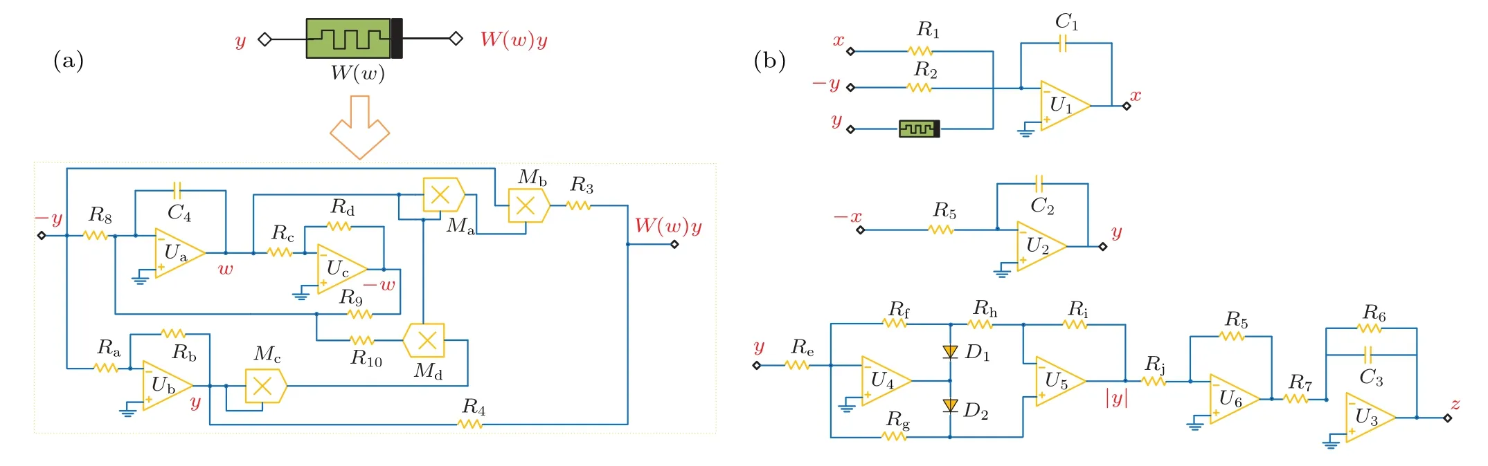
Fig.12.Schematic circuit diagram of chaotic system: (a)memory resistor model equivalent circuit and(b)main circuit.
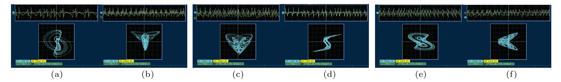
Fig.13.Voltage signal diagram and phase diagram of hardware circuit obtained from UNITUTD2102CM oscilloscope: (a)x-y plane, (b)x-z plane, (c)y-z plane,(d)x-w plane,(e)y-w plane,and(f)z-w plane.
6.Application in image encryption
Compared to text data, image data has the characteristics of a large amount of data, strong data correlation, and a large amount of redundant information, which makes traditional text-based cryptography no longer suitable for image encryption systems.As a nonlinear system, chaotic systems provide chaotic sequences with good randomness due to their processing sensitivity and unpredictability.This is exactly what a good encryption system must have.
6.1.Image encryption scheme
This article uses an encryption algorithm for plain associated scrambled images, as shown in Fig.14.The specific process will be described below.
Step 1 Convert the plain image into a matrixPofM×Nsize.
Step 2 Set the system keyK= (x0,y0,z0,w0,r1,r2),wherex0,y0,z0,w0are the initial values of the chaotic system,andr1,r2are random integers from 0-256.
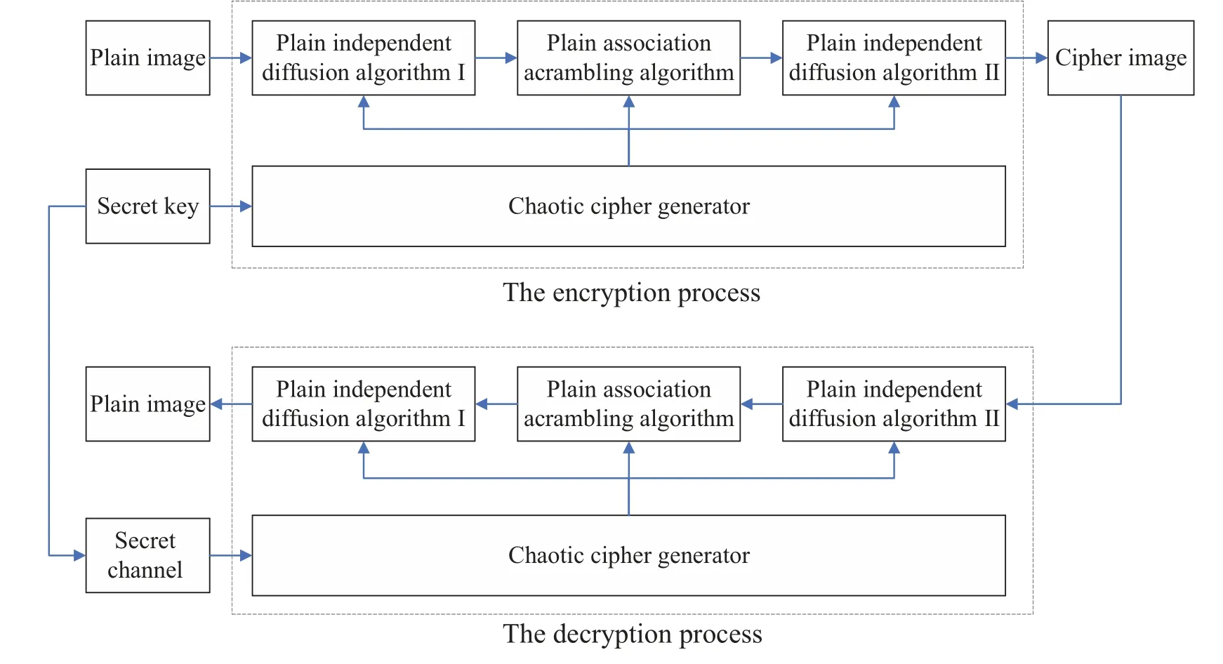
Fig.14.Plain association scrambling algorithm flowchart.
Step 3 Using the random sequence generated by the memristive chaotic system, six pseudo-random matrices are generated,which are sequentially recorded asX,Y,Z,W,U,andV,the size of all matrices isM×N.
Step 4 Using the plaintext independent extension algorithm I,the plaintext image matrixPis transformed into a matrixAusing a random matrixX.
Step 5 The scrambling algorithm for plaintext correlation eliminates the correlation between adjacent pixel points in the original image by disturbing the pixel position.Use the random matricesZ,W,U, andVto traverse all pixel points in imageAin a scanning order from left to right and from top to bottom in the coordinates of theAmatrix, convertingAinto imageB.
Step 6 The plaintext independent diffusion algorithm repeats Step 4,with the difference being that it spreads forward from the last pixel of the image,and uses the matrixYto diffuse imageBfor a second time to obtain the encrypted imageC.
The decryption process is the inverse operation of the encryption process.
Set keyK=(1.3254, 1.5321, 1.2356, 2.3265, 35, 201)and encrypt and decrypt Lena, Baboon, and Pepper images.The experimental results are shown in Fig.15.
Figures 15(a), 15(d), and 15(g) show plain images, figures 15(b), 15(e), and 15(h) show encrypted images, and figures 15(c),15(f),and 15(i)show decrypted images.
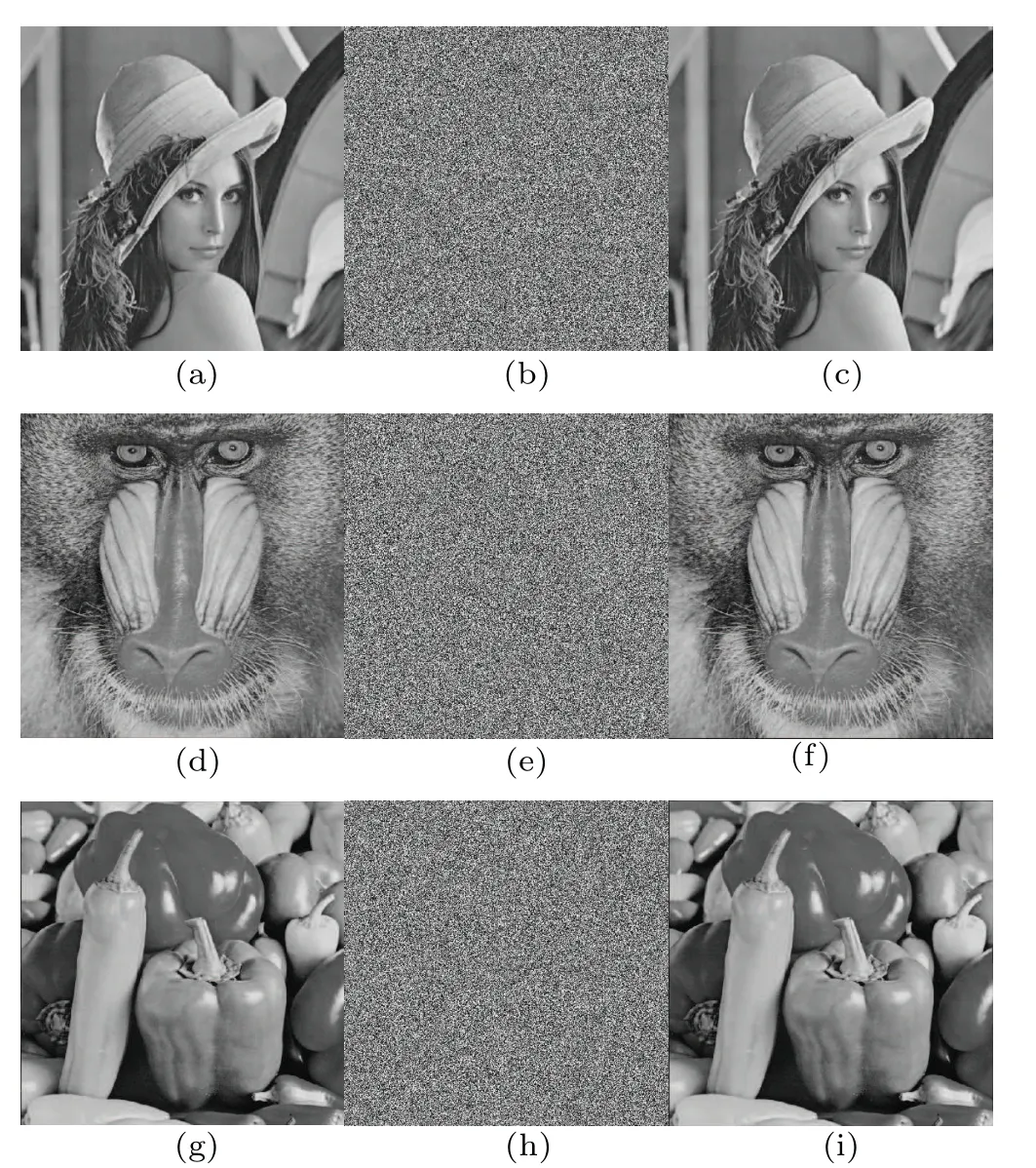
Fig.15.Experimental results of image encryption and decryption: (a)Lena,(d) Baboon, (g) Pepper; ciphered images: (b) Lena, (e) Baboon, (h) Pepper;decrypted images: (c)Lena,(f)Baboon,(i)Pepper.
6.2.Analysis of security performance of encryption scheme
6.2.1.Key space
The key space is a collection of all the keys.In order to resist exhaustive attacks, a good image cryptosystem should have a large enough key space.For the image encryption system proposed in this paper, the keyK=(x0,y0,z0,w0,r1,r2)is the initial value of the system(3)and two random integers of 0-256,where the steps ofx0andw0are 10-16,the steps ofy0are 10-15, the steps ofz0are 10-14, and the steps of two random numbers are 1.Therefore, the size of the key space is at leastS=1.2×1053, and the corresponding key lengthL=log2S ≈176 bit.The large enough key space indicates that the system is an excellent encryption system.
6.2.2.Histogram andχ2statistical value analysis
Generally,ciphertext statistics are mainly discussed from two aspects:the histogram of the ciphertext image and the correlation of adjacent pixels in the ciphertext image.As can be seen from Fig.16,the histogram of the ciphertext image is uniform and flat,while the histogram of the plaintext image fluctuates, indicating that the effective information in the image can be well encrypted.Usingχ2the difference in the number of statistics analyzes adjacent pixel points.Analyze adjacent pixel points using quantitative differences inχ2statistics.The definition ofχ2is
wherefiis the observed frequency distribution andgiis the theoretical frequency.Theχ2test is performed on the image histogram, and the results are shown in Table 2.It can be seen from the table that theχ2statistical values of the three plaintext images are significantly greater thanχ20.01(255) =310.45739,while theχ2statistical values of the ciphertext images are all less thanχ20.01(255),indicating that the ciphertext images are approximately uniformly distributed.
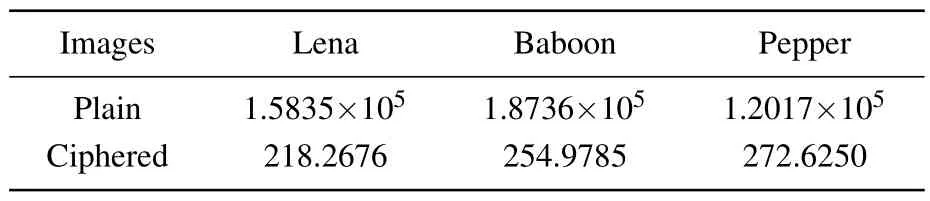
Table 2.Values of χ2 statistics.
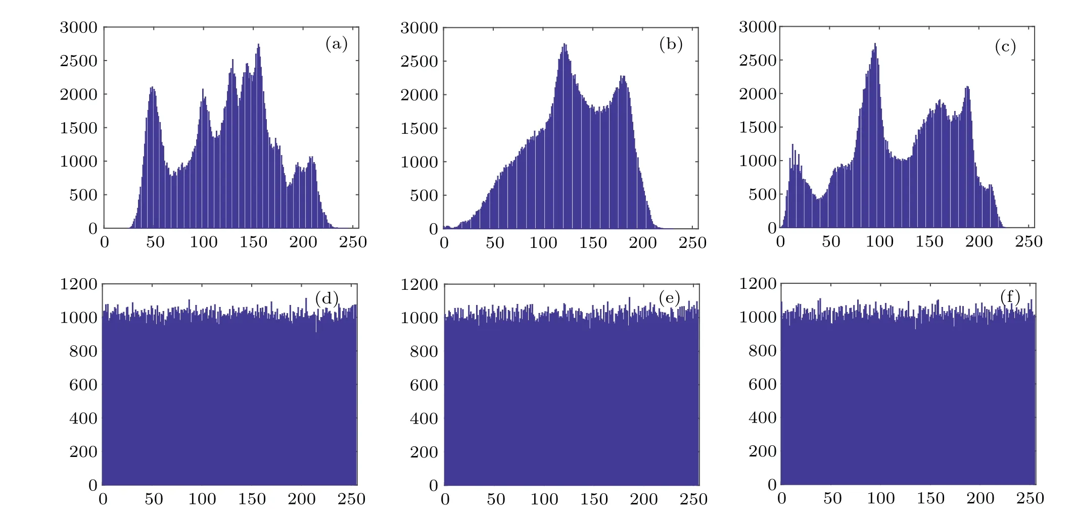
Fig.16.Histograms of plaintext and ciphertext images: histogram of plain image(a)Lena,(b)Baboon,and(c)Pepper; histogram of ciphered image: (d)Lena,(e)Baboon,and(f)Pepper.
6.2.3.Correlation coefficient analysis
Another indicator for evaluating correlation is the correlation coefficient,which mainly reflects the correlation of pixels in different directions of the image.The correlation coefficientDis defined as
wherexiandyiare the gray values of two adjacent pixel points in the image,whileBy changing the value of the sum,the correlation coefficients of the image in different directions are obtained.Table 3 records the correlation coefficients of plaintext and ciphertext images in different directions and compares them with other literature.The comparison reveals a notable distinction in the correlation patterns between adjacent pixels in plaintext and ciphertext images.In plaintext images,there exists a strong correlation between adjacent pixels,indicating their close relationship.Conversely,in ciphertext images,the correlation between adjacent pixels approaches zero,suggesting that these pixels are essentially independent and unrelated to each other.This observation underscores the effectiveness of our proposed encryption method, which demonstrates comparable performance to the other four methods under consideration.
6.2.4.Key sensitivity analysis
Key sensitivity analysis refers to the difference between two ciphertext images when the key undergoes very small changes.After a key change,if there is a significant difference between the two ciphertext images,it indicates that the key is sensitive,andvice versa,it indicates that the key sensitivity is very poor.the key space,change the key at the corresponding magnitude,and encrypt the image.All three parameters reflect the sensitivity of the key.The three indicators and their theoretical values obtained are shown in Table 4.It can be observed that the average and theoretical values of the three indicators are very close, indicating that the key of the image cryptosystem is highly sensitive to encryption processing.
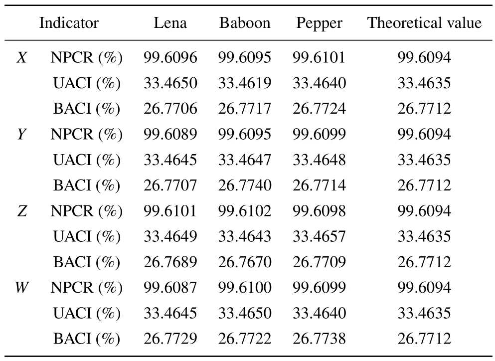
Table 4.Key sensitivity analysis results
NPCR, UACI, and BACI are often used to analyze key sensitivity.The number of pixels change rate(NPCR)is used to compare the values of pixel points at corresponding positions in two images,recording the proportion of different pixel points to all pixel points.The unified average changing intensity (UACI) is used to record the pixel difference value, and then calculate the average value of the maximum difference,block average changing intensity (BACI) calculates the ratio of the average value of several pixel points to the maximum difference between the pixel points.Select a key randomly in
7.Conclusion
In this paper,a quadratic voltage-controlled memristor is introduced into the Rucklidge chaotic system,and a dissipative 4D memristive chaotic system with only one equilibrium point is obtained.Systematic analysis revealed the specific properties of the memristive chaotic system proposed here: (i)high complexity, high values of SE and C0; (ii) single-parameter multiple attractors,16 types of attractors obtained by changing only one parameter, including 8 chaotic attractors, 3 periodic attractors, and 5 quasi-periodic attractors; and (iii) rich transient behavior: among five transient behaviors one is chaotic to periodic and others are intermittent chaos;Two of transient behaviors also exhibit the phenomenon of symmetric periodic attractors.The hardware circuit implementation of this chaotic system proves its feasibility on the physical level.This system is applied to image encryption,with the excellent security proved from the aspects of key space, histogram, and correlation.With its high complexity and diverse transient behaviors,this system can significantly reduce costs in engineering applications while providing valuable guidance for practical implementations.
Acknowledgements
Project supported by the National Natural Science Foundation of China(Grant No.U1612442)and Science and Technology Special Foundation Project of Guizhou Water Resources Department(Grant No.KT202236).
杂志排行

Chinese Physics B的其它文章
- Single-qubit quantum classifier based on gradient-free optimization algorithm
- Mode dynamics of Bose-Einstein condensates in a single-well potential
- A quantum algorithm for Toeplitz matrix-vector multiplication
- Non-Gaussian approach: Withstanding loss and noise of multi-scattering underwater channel for continuous-variable quantum teleportation
- Trajectory equation of a lump before and after collision with other waves for generalized Hirota-Satsuma-Ito equation
- Detection of healthy and pathological heartbeat dynamics in ECG signals using multivariate recurrence networks with multiple scale factors