Dynamics of magnetic microbubble transport in blood vessels
2023-10-11JieChen陈杰ChenghuiWang王成会andRunyangMo莫润阳
Jie Chen(陈杰), Chenghui Wang(王成会), and Runyang Mo(莫润阳)
Institute of Shaanxi Key Laboratory of Ultrasonics,Shaanxi Normal University,Xi’an 710119,China
Keywords: magnetic microbubbles,targeted drug delivery,ultrasound,magnetic field
1.Introduction
Ultrasound combined with microbubble contrast agents has been widely demonstrated as a method of improving the delivery of drugs and genesin vitroandin vivo.However,the technique is limited by the relatively low delivery efficiencies achieved.Encapsulated microbubbles coupled with magnetic nanoparticles are referred to as magnetic microbubbles(MMBs), and are regarded as a recent development with the potential to greatly improve the efficacy of drug delivery and procedure sonoporation.[1–4]The shell elasticity allows volume oscillations in an acoustic field,which can be more easily controlled by an external magnetic field and demonstrate great potential as a drug delivery vehicle and multi-modal imaging tool.[5–7]
Gene transfection enhanced by MMBs was first demonstrated by Strideet al.,[8]and then confirmed by Mulvanaet al.[9]and Vlaskouet al.[10]One possible mechanism is that both the concentration and proximity of the MMBs to the target cells are improved by the magnetic field.[11]However,this assumption needs to be further confirmed[12–14]and more experiments are needed.The effects of nanoparticles on the dynamic and acoustic responses of MMBs have been characterized.[15,16]The harmonic response and cavitation activity have been investigated experimentally.[17,18]Zhaoet al.[19]found experimentally that the magnetic susceptibility is proportional to the square of MMB radii.Meanwhile,MMBs also show powerful potential in tumor therapy and targeted drug delivery.[20,21]Both magnetic nanoparticles and nanodrugs can be released from oscillating MMBs.[12,14]Zhanget al.[2]reported an application in sonothrombolysis and confirmed that MMBs can be retained by a rotational magnetic field against blood flow.Recently, a series of sonodynamic therapies induced by oscillating MMBs in external fields were further verified.[22,23]Several specific devices were designed to maximize the superiority for tumor treatments.[13,24,25]
The kinetics and regulation of MMBs are the basis of its application.To describe the volume oscillations exposed to ultrasound, Mulvanaet al.[16]conducted a preliminary modelling study.A fixed volume fraction of solid nanoparticles was used to examine the influence of an additional magnetic layer.Recently, Zhaoet al.[26]developed a multilayer magnetic shell model and the nonlinear oscillating characteristics were numerically evaluated.However,these studies have their limitations, because they ignore the influence of an applied magnetic field and non-spherical pulsation.Previous numerical studies on bubble dynamics in a magnetic field often were replaced by the dynamic of one or more non-magnetic bubbles in magnetic fluids.In this way, Lind[27]simulated the dynamics of non-spherical MMBs and showed that the magnetic susceptibility difference between bubbles and the ambient fluid can provide an additional means of flow control.Malvaret al.[28]formulated a new version of the Rayleigh–Plesset equation by considering the magnetic stress contribution and proved that the bubble oscillating motion can be controlled and its collapse avoided when a high magnetic field is applied.Chenet al.[29]expanded this work and found that the vibration amplitude could be enhanced by the magnetic field.Unfortunately, the coupling effect between vibration and translation has not been investigated and this incomplete understanding of the transport mechanism of MMBs makes some phenomena observed from experiments difficult to explain.
Mathematical study acts an important role in exploring this mechanism by offering detailed mechanical processes that would be difficult or impossible to seein vitroorin vivo.In this work, theoretical models are established to simulate the dynamics of MMB transport in blood vessels under acoustic pressure and magnetic fields.In addition,some parameters associated with drug release are also simulated, especially the shear stress generated by bubble pulsation, which increases with the intensity of the applied magnetic field.The study attempts to provide insight into the details of MMB motion during targeted transport and support some experimental conclusions.
2.Theory and method
2.1.Translation in blood vessels
MMBs transported in blood vessels are capable of targeted delivery and drug release when driven by ultrasound and magnetic fields.As shown in Fig.1, typical processes were summarized as translation, pulsation and drug release.MMBs can be retained in the tumor region under the guidance of a magnetic field, and perform drug release behavior in ultrasound.
In a steady vessel flow, a single MMB is governed by three forces,expressed as
wheremeffis the effective mass of the MMB including the added mass,and the three terms on the right side of Eq.(1)are the magnetic force,buoyancy and drag force,respectively.
In addition,meffis small enough relative to other factors,which means the terminal velocity can be rapidly obtained.The process of MMB transport in the target region is shown in Fig.2.When MMBs arrive at the targeted region,FMis generated by a linear Halbach array of magnets,which is used in the experiment work of Barnsleyet al.[24]and expressed by
wheremis the total magnetic moment of the magnetic nanoparticles,χbis the magnetic susceptibility of the bubbles,µ0is the permeability of vacuum space,andBis the magnetic induction.The expressionsχb=(6×10⁻⁶m)R2, dB/dz=900e(-0.75zmag/mm)T/mandB= 1.1e(-0.63zmag/mm)Tare cited from the literature.[19,24]
The vessel is assumed to be a laminar cylindrical channel in thex-axis direction,[24]and the liquid flow ratevFis given by
wherevAis the mean velocity andRCis the channel radius.
Taking blood as a Newtonian fluid, the drag forceFDis followed by Stokes’law and given by viscous drag
whereηLis the liquid viscosity,Ris the temporary radius andvis the velocity vector of the transport MMBs.Only the two dominant forcesFMandFDare considered in this model;one can obtain the result by combining Eqs.(1)–(4),given as
IfFMis uniformly distributed in the local region,the component ofvinz-directionvzis approximated as a constant.This method has been verified by simulations and experiments in the literature.[24]
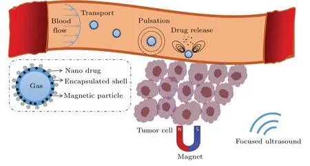
Fig.1.Sketch of MMBs used for targeted drug delivery.

Fig.2.Targeted delivery of MMBs in a flowing channel.The channel radius is RC with a flow in the x-direction, and each bubble is trapped in the target area marked by the shaded region from x0 to xM.Linear Halbach array magnets with thickness dmag are fixed at a distance zmag from the channel center.The dotted lines show the bubble trajectories under the attraction of the magnets.
Primarily, our model is based on the one-dimensional cylindrical channel flow along thex-direction according to Eq.(3), and the magnetic force is applied in thez-direction.There is no driving force in they-direction, so the displacement in they-direction is ignored.Further, the coordinate componentsx(t) andz(t) are obtained by integrating the velocity components in Eq.(5).Taking the original coordinate position as (x0,y0,z0),x(t) andz(t) can be represented as follows:[24]
Due to the strong magnetic force,MMBs are assumed to have no slippery contact with the channel wall.Thereby,the capture efficiency is expressed as[24,25]
2.2.Dynamic model of coupled motion
Previous studies have shown that magnetic nanoparticles have little effect on acoustic response, and MMBs are also not obviously affected by magnetic fields.[16]Donikove’s model[30]describes the vibration of a thin-shell bubble in an infinite liquid,represented as
whereRandR0are the transient radius and the initial radius,respectively.˙Ris the bubble wall velocity, the liquid density and viscosity areρLandηL,respectively,σis the surface tension,Pg0is the equilibrium pressure,γis the polytrophic exponent,Pac(t)=Pasin(2π ft)is the acoustic driving pressure,andSrepresents the role of the encapsulated shell and is described by
whereκ(˙R/R)=κ0+κ1˙R/Ris the shell surface viscosity (in kg·s-1) andζis the shell surface elasticity (in N·m-1).The values of shell parametersκ0,κ1andζare obtained from the literature,[30]and some observations[17,21,30]show that the stiffness and viscosity of the shell are related to magnetic particle concentration.When MMBs move in the vessel,[31,32]the kinetic energy of the system is contributed by pulsation and translation,which is defined as
Considering the work done by pulsation and external forcesFexacting on MMBs, the potential energy[33]of the system is
From the right terms of Eq.(8), ΔPincludes an additional magnetic pressurePM,andPMis given by Lind:[27,34]
whereµ0is the vacuum permeability, andB0is the magnetic field strength and generally taken as 1–2 T.[8,16,27]The magnetic susceptibility difference Δχis a dimensionless value between the MMBs and the ambient fluid.Fexin Eq.(11) denotes the external forces acting on the MMBs,and can be written as
The right terms of Eq.(14) correspond to Levich viscous drag,[35]magnetic force and secondary Bjerknes force,[36]and the bubble volume isVb.
In addition,the Lagrangian quantity of the system is
If other dissipative factors are ignored, the Lagrange equation is expressed as
takingR,x,zand ˙R, ˙x, ˙zas generalized coordinates and velocities,respectively.This operation yields the equations of MMB dynamics
Equations (17)–(19) are the coupled formulas describing the radial pulsation and translation of MMBs in the vessel.The contributions of the magnetic field and vessel wall are considered, such as the magnetic pressure, magnetic force, Bjerknes force,velocity gradient and the system kinetic energy adjusted by the vessel wall, which are the main factors in describing the boundary effect of fluid–solid interaction.This model has a similar form to the non-magnetic bubbles in a magnetic fluid,[28,29]and it also agrees with the reported models of gas bubbles in a channel and near a curved wall.[31,32]For more complex cases, the reflection and absorption of the vessel wall, even for non-spherical jets, remain to be further clarified.
Assuming MMBs vibrating at small amplitudes, the eigenfrequency[37]is obtained by Eq.(17)as
wheref*0andf0correspond to the vessel and infinite environment,respectively.
2.3.Drug release dynamics
Safely increasing transfection efficiencies in sonoporation(the amount of drug uptake by cells)remains an important issue and the shear stress caused by microstreaming has been demonstrated as an effective means.When a drug particle is detached from a MMB, the force balance relationship[12]is satisfied:

The microstreaming, generated by vibrating bubbles when they approach the wall, can be described byψ(r,θ) in spherical coordinates.[38]The dimensionless velocityu*is a function ofθand given by Eq.(24).
whereAis the dimensionless source strength depending on the oscillation mode of the bubble.To simplify the description,a dimensionless radial functionf(r)=is introduced to demonstrate the streamline distribution.
According to Nyborg’s theory,[39,40]if the pulsating bubble is close to the vessel wall,thexcomponent of shear stress on the cells can be quantified by
whereξmis the pulsating amplitude andδ=x/ld.
3.Numerical simulation
The parameters used in numerical analysis are as follows:R0=2 μm,P0=105Pa,ρL=103kg·m-3,σ=0.085 N·m-1,ηL= 10-3Pa·s,Pa= 60 kPa, Δχ= 0.1, andf= 1 MHz.Typical parameters of the shells of MMBs areκ0=1.45×10⁻⁸kg·s-1,κ1=6×10-15kg andζ=0.2 N·m-1.Moreover, the drug particles are simulated withdP= 100 nm,ρP=3×10³kg·m-3andCA=0.5.
3.1.Transport in gradient magnetic field
3.1.1.Magnetic field analysis
The strength and gradient of the magnetic field are essential for MMB localization.Figure 3(a) plots the fitting curve ofBas a function ofzmaggiven asB=1.1e(-0.63zmag/mm) T.It matches the experimental data[24](blue dots in Fig.3(a))very well.The gradient of the magnetic field depends onzmagand is expected to be dB/dz=900e(-0.75zmag/mm) T/m (inset plot in Fig.3(a)).The values ofB·dB/dzare 18 T2·m-1and 53.2 T2·m-1in the literature,[8,11]which agree with our data of 18.1 T2·m-1and 54.6 T2·m-1atzmag= 2.9 mm and 2.1 mm, respectively.The magnetic forceFMacting on MMBs is related tozmagin Fig.3(b).A semilog plot is presented to emphasize the exponential properties ofFMwithzmag.The marked data of 100 μm radius atzmag=4 mm is 2.142×10⁻⁷N, which agrees with experimental observations.[19]TheFMmarked as 8.568×10⁻¹¹N for a radius of 2 μm is about 2500 times for 100 μm.This variation follows the ruleFM~R2due to magnetic nanoparticle numbers.When MMBs are attracted by magnets, their position and acting forces are changed with time.Larger bubbles carry more magnetic particles and produce stronger magnetic force.In Fig.3(c),a bubble with 2 μm radius moves fromz=3 mm toz=0 mm at the latest and takes 0.09 s,which is much longer than a larger one.This suggests that the size sorting of MMBs could be assisted by an external force,[41]and a better operation on aggregation would be realized by the attached magnetic force.Figure 3(d)shows the competition between forces on a bubble with 2 μm radius atz0=3 mm.When the bubble is close to the magnets, the velocity is gradually accelerated by the magnetic force,and the drag force is also increased until terminal equilibrium is reached.As expected, the values of both the added mass force and buoyancy force are smaller than magnetic and drag forces; this observation supports the simplification of Eq.(5).

Fig.3.Responses of MMBs to the linear Halbach array magnets.(a) Character of gradient magnetic field; (b) relationship of FM ~zmag;(c)transport in z-direction guided by magnets;(d)forces acting on a bubble of R=2 μm at z0=3 mm.
3.1.2.Transport trajectory
In a vessel ofRC=0.25 mm,MMBs moving fromx0=0 mm toxM=2 mm along thexaxial direction are manipulated by the linear Halbach array magnets.For mean flow velocities ofvA= 20 mm·s-1and 40 mm·s-1, trajectories are shown in Figs.4(a) and 4(b), respectively, and each horizontal line corresponds to a starting position.As an example for comparison, the black line is retained atx= 2 mm for 40 mm·s-1andx=1 mm forvA=20 mm·s-1.Higher velocityvAproduces a horizontal displacement with a longer distance.Smaller distance to the magnets leads to better capture of MMBs with a shorter horizontal displacement, while higher flow velocity weakens the capture efficiency.The red line in Fig.4(c)is the fitting curve from Eq.(7)that matches the calculated results(statistics from a large number of tracks),indicating that capture efficiency decreases asvAincreases,and the capture behavior observed in experiments can also be quantified by Eq.(7).[24,25]In other words, Eq.(7) can serve as a simple method to predict the capture efficiency without calculating tracks.The distance to the magnets is also an essential parameter in MMB capture.The relationship between translation velocityvzand separation distancezmagis shown in Fig.4(d), Eq.(5) shows an exponential relationship between them,and the marked data represent the speed at several specific distances.Above all, the trajectories of MMBs can be established by the model shown in Eq.(6), and the capture efficiency between calculation and the analytical formula has been well verified.
3.1.3.Capture efficiency
MMBs can be localized at the target region when they are attracted by a gradient magnetic field.Capture efficiency is studied by Eq.(5) using the control variable method.These parameters include the component of transport velocity in thezdirectionvz, mean velocityvA, vessel radiusRCand magnet lengthxM;the results are shown in Figs.5(a)–5(d).WhenRC=0.25 mm,the efficiency increases with improvedvzandxM(Figs.5(a)and 5(b))and decreases withvA(Fig.5(c)),so a higher moving velocity and longer magnets can be more efficient,whereas a stronger flow velocity has the opposite effect.However, ifvAandxMare constant, smallerRCand largervzare more effective as shown in Fig.5(d).

Fig.4.Transport properties of MMBs in a blood vessel.(a)and(b)The trajectories in the x–z plane at zmag=3.25 mm,vA=10 mm·s-1 and 20 mm·s-1,respectively;(c)capture efficiency related to vA;(d)vz determined by zmag.

Fig.5.Capture efficiency of MMBs.(a) RC =0.25 mm, xM =2 mm; (b)vz =3 mm·s-1, RC =0.25 mm; (c)xM =2 mm, RC =0.25 mm;(d)vA=20 mm·s-1,xM=2 mm.
3.2.Pulsation in uniform magnetic field
3.2.1.Pulsation in unbound case
To study MMBs pulsating in a uniform magnetic field,first, the unbound case without the vessel wall constraint was simulated.TheR–tcurves with code testing are shown in Fig.6(a); the parameters used here areR0= 1.4 μm,f= 3 MHz andPa= 100 kPa.The prediction of the proposed model (green line) matches well with the data (red circles) in the literature.[30]To highlight the effect of the shell,an unshelled bubble was used for comparison data(blue line).The shell effect reduces the amplitude and increases the harmonics.[42]Figure 6(b) shows the vibration of MMBs(R=2 μm,Pa=60 kPa andf=1 MHz) in magnetic fields ofB0=1 T,1.5 T and 2 T.The vibration amplitude increases withB0and one possible mechanism is that magnetic field promotes acoustic response.Similar results were found in Lind’s theoretical analysis of non-spherical bubbles in a magnetic liquid,[27]and it is also supported by violent bubble oscillation manipulated by external fields in a magnetic fluid[28,29]and electric medium.[43]Moreover, after removing the ultrasonic field at 6.5 μs, damping oscillations of MMBs are also displayed, and the final static radius is increased with the intensity of magnetic field.
As shown in Fig.6(c), the oscillation amplitude near the resonance frequency increases significantly with magnetic field intensity.ConsideringB0=0 T,the maximum amplitude corresponding to the frequency is 2.6 MHz,which agrees with the 2.63 MHz calculated by Eq.(24) usingζ=0.2 N·m-1.Meanwhile,the resonant peak shifts from 2.6 MHz to 1.4 MHz after applyingB0=2 T, and the resonance frequency drops because the magnetic field increases the final static radius.Figure 6(d) depicts the curve of magnetic pressurePMfor Δχ=0.01, 0.05 and 0.1; the larger the susceptibility difference is, the fasterPMincreases withB0improvement.Conversely, bubbles in liquid oxygen with susceptibility 0.0035 have a smaller magnetic pressure of 1.4 kPa atB0=1 T,[34]which directly supports the idea that magnetic pressure is determined by the magnetic field and susceptibility difference between MMBs and the ambient fluid.
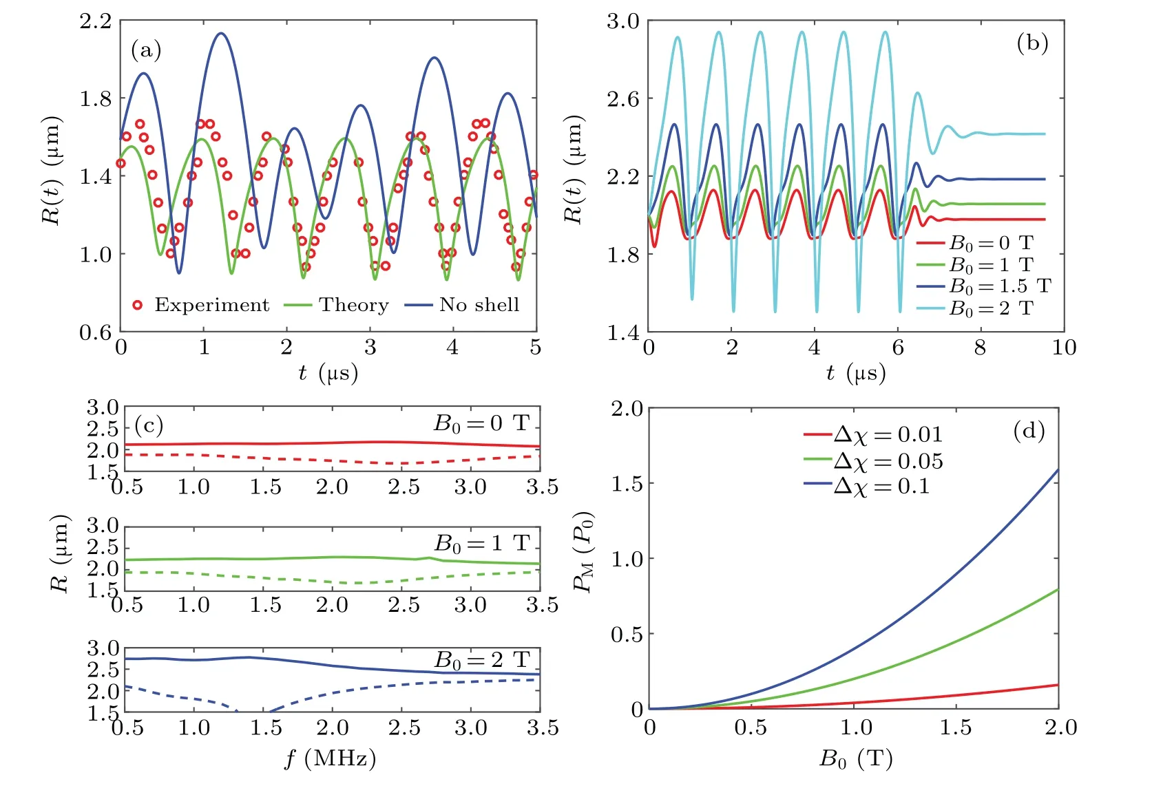
Fig.6.MMBs vibrating in a uniform magnetic field.(a) Code testing and MMB analysis in B0 =0 T (f =3 MHz, Pa =100 kPa); (b) R–t curves adjusted by the magnetic field(f =1 MHz,Pa=60 kPa);(c)oscillating amplitude in B0=0 T,1 T and 2 T(Pa=60 kPa),Rmax (solid line)and Rmin (dashed line);(d)PM determined by B0 and Δχ.
3.2.2.Resonance frequency
First,the shell effect on resonance frequencyf0is shown as an unbound case in Fig.7(a).The hybrid shell has higher surface elasticity compared with an uncoated bubble and yields a higherf0.The prediction of the green line withζ=0.3 N·m-1aligns with the experimental data,[44]and the discrepancy decreases with increasing bubble size.Moreover,f0can also be used to evaluate the shell elasticity.[45]As shown in Figs.7(b) and 7(c), a largerRCand further distanceldyield a lower resonance frequency.Moreover,f*0/f0decreases greatly with increasingRand the observed rule is consistent with the literature,[46,47]indicating the reliability of this model.

Fig.7.Resonance frequency of single MMBs.(a)Unbound;(b)in the vessel center;(c)close to the vessel wall.
3.2.3.Pulsation near vessel wall
Oscillating MMBs near the wall were used to verify the validity of the model.The red circles in Fig.8(a) represent the data carried by Garbin[48]and the green line is the predicted result of this model.The two results almost coincide and the deviation may be attributed to uncertainldor nonspherical pulsation.In contrast, a bubble far away from the wall is seen as a free one, shown as a blue line; a shorter period and larger amplitude imply that boundary constraints suppress oscillations.[49,50]As shown in Fig.8(b),the boundary constraint causes a resonance frequency decrease,and the magnetic field obviously alters the oscillatory response when compared with the unconstrained case as shown in Fig.6(c).
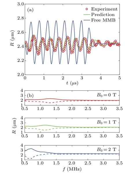
Fig.8.Pulsation of MMBs near the vessel wall.(a) Compared with Garbin’s experimental data;[48] (b) oscillating amplitude in various magnetic fields,Rmax (solid line)and Rmin (dashed line).
3.3.Coupled motion
The coupled motion of MMBs near the vessel wall is shown in Fig.9(a).The three cases have similar trends.There is a much stronger response in the case of both fields than in the other cases,which could be ascribed to the synergistic manipulation.On the other hand, the pulsation in both fields is consistent with the non-spherical jet behavior near the vessel wall,[27]indicating that the volume vibration is improved,and then non-spherical deformation and jet generation.However,further studies on jet behavior go beyond our spherical hypothesis of MMBs.If the MMBs are far from the vessel wall andld=20 μm, Fig.9(b) displays the translational motion.The motion toward the wall is weaker in the acoustic field than in the magnetic field, which can be described by the Bjerknes force decays with (ld)2.The difference between the red and blue lines is attributed to the fact that the Levich drag in both fields is twice the Stokes drag in the magnetic field.Therefore,a rapid translation of the red line is observed at the initial stage and then the blue line approaches quickly as the MMBs approach the wall.This indicates that the translation of MMBs away from the vessel wall is mainly controlled by the magnetic force, while near the wall it is the Bjerknes force.Moreover,the combined application of magnetic and ultrasonic fields is shown with a shorter horizontal distancex(t).The capture of MMBs can be improved by the synergistic effect between magnetic force and Bjerknes force.
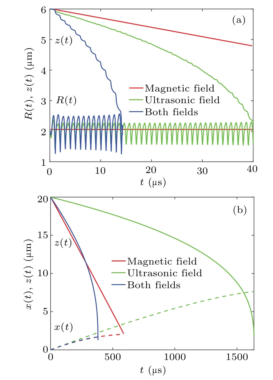
Fig.9.Coupled motion of MMBs approaching the vessel wall.(a)Close to wall;(b)far from wall.
3.4.Transport distance of drug particles
MMBs carrying drugs and magnetic nanoparticles have the potential to improve localized drug delivery and tumor therapy.[11–13]It is assumed that the slight deformation of the vessel wall is replaced by a rigid wall.In Fig.10(a),the evolution of transport distance vs.time by solving Eq.(18) and Eq.(23)is compared with the reported trajectory.[12,14]Overall,the similar trend in both results confirms that the model can predict the drug release well.Figures 10(b),10(c),10(d)show the influences ofB0,PaandR0on the transport distance, respectively.A stronger magnetic field,higher acoustic pressure and suitable bubble radius provide a further transport distance and allow better drug release.The ultrasound triggers MMBs with violent vibrations and liquid microstreaming improves the drugs separated from MMBs.For the latter two graphics,the displacement of released drug particles corresponds well with Guillaume’s observations,[14]and the existing difference may be explained by the simplified velocity distribution and non-spherical oscillation.
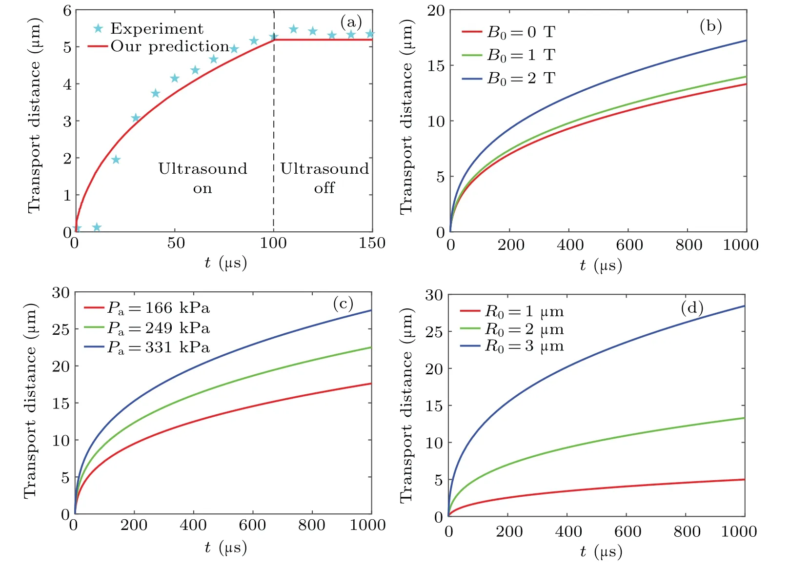
Fig.10.Transport distance of drug particles.(a)Compared with experimental data in the literature,[25] (b)effects of intensity B0,(c)effects of driving pressure at B0=0 T,(d)effects of MMBs radius at B0=0 T.
3.5.Acoustic streaming

Fig.11.Mechanical effect associated with vibrating MMBs near the vessel wall.(a) Streamline distribution; (b) spatial dimensionless velocity;(c)shear stress associated with MMB position(f =1 MHz);(d)shear stress determined by acoustic driving frequency f and B0 at x/R0=0.4,ld=R0.
Acoustic streaming pattern and direction are usually related to the acoustic driving frequency and amplitude.Streamlines help clarify the trajectory of drug release.[14]Simulated results are shown in Fig.11(a).Compared to Marmottant’s pattern,[51]our calculation provides a surprisingly similar streamline distribution away from the bubble center.It is beneficial to understand the process of drug particle release from oscillating MMBs.The non-dimensional release velocityu*as a function of spatial angleθis shown in Fig.11(b).The release velocityu*is strongly dependent on the streaming direction and distribution;its maximum value is obtained atθ=0.Figure 11(c)is shear stress distribution on vessel wall when the bubble oscillates at a distanceld,the negative stress means an opposite direction.At the position ofx/R0=0.3,the variation in shear stress with driving frequency is shown in Fig.11(d);the maximum value corresponds to the resonance frequency being driven.This indicates that the combined magnetic and ultrasonic fields could improve shear stress,which may generate sonoporation to enhance transfection,[8,27]and the sonothrombolysis test implies that a better lysis rate is achieved by more cavitation nuclei retained in magnetic targeting region.[11]
3.6.Therapy effect analysis
As noted above, the behavior of MMBs driven by external fields was numerically analyzed, and the results are consistent with the experimental data in the literature.Experiments[8,11,12]reported that the differences in aggregated drug particles in the tumor area caused by external fields eventually lead to different therapeutic effects.[12,13]Lind[27]suggested that a stronger jet formed by the combined application of acoustic–magnetic fields and the generated highspeed collapse is most likely to maximize cell poration and gene/drug delivery.Our observations indicate that the magnitude of shear stress near the vessel wall was increased under applied external fields.In contrast, a uniform magnetic field is verified to weaken the oscillating gas bubble without coated magnetic particles, and is supported by inhibition of sonoluminescence[52–54]and reduction of the blood–brain barrier opening volume.[55]These facts could serve as contrary evidence to approve the model in this work; fiercer pulsation of MMBs is achieved by combined acoustic and magnetic fields.A higher shear stress caused oscillating MMBs in the combined acoustic and magnetic fields, which aligns with the results[11–13]in sonothrombolysis and tumor therapy.The magnetic force makes more MMBs stay in the target area and magnetic pressure improves the pulsation amplitude.The higher shear stress on the vessel wall is expected to enhance drug delivery efficiency.
4.Conclusions
An analytical model of single MMBs, which are transported in blood vessel and exposed to ultrasound and magnetic fields, was established.Our simulation includes translation,vibration and coupled motion of both.Vibration streaming,shear stress and their effects related to particle capture are also predicted.The results suggest that both transport and pulsation are well manipulated by the magnetic field due to the magnetic force and magnetic pressure.The effects of the vessel wall and external fields on the resonance frequency are further evaluated.Acoustic streaming near the vessel wall is demonstrated;some parameters related to drug release are quantified and consistent with the experimental data in the literature.In summary,a combined application of ultrasound and magnetic fields not only improves the capture of MMBs in the targeted region but also increases the shear stress near the vessel wall,which may enhance the permeability of the tissue,thus leading to better drug uptake.These results provide better understanding of the mechanism of MMBs in clinical applications and can be used to optimize the delivery strategy.
Acknowledgement
Project supported by the National Natural Science Foundation of China (Grant Nos.12074238, 11974232, and 11727813).
猜你喜欢
杂志排行

Chinese Physics B的其它文章
- Dynamic responses of an energy harvesting system based on piezoelectric and electromagnetic mechanisms under colored noise
- Intervention against information diffusion in static and temporal coupling networks
- Turing pattern selection for a plant–wrack model with cross-diffusion
- Quantum correlation enhanced bound of the information exclusion principle
- Floquet dynamical quantum phase transitions in transverse XY spin chains under periodic kickings
- Generalized uncertainty principle from long-range kernel effects:The case of the Hawking black hole temperature