Effect of TbF3 diffusion on the demagnetization behavior and domain evolution of sintered Nd–Fe–B magnets by electrophoretic deposition
2023-10-11XueJingCao曹学静ShuaiGuo郭帅YuHengXie谢宇恒LeiJin金磊GuangFeiDing丁广飞BoZheng郑波RenJieChen陈仁杰andRuYan闫阿儒
Xue-Jing Cao(曹学静), Shuai Guo(郭帅), Yu-Heng Xie(谢宇恒), Lei Jin(金磊), Guang-Fei Ding(丁广飞),Bo Zheng(郑波), Ren-Jie Chen(陈仁杰), and A-Ru Yan(闫阿儒)
1CISRI and NIMTE Joint Innovation Center for Rare Earth Permanent Magnets,Ningbo Institute of Material Technology and Engineering,Chinese Academy of Sciences,Ningbo 315201,China
2CAS Key Laboratory of Magnetic Materials and Devices,Ningbo Institute of Material Technology and Engineering,Chinese Academy of Sciences,Ningbo 315201,China
Keywords: sintered Nd–Fe–B magnet,electrophoretic deposition,grain boundary diffusion,domain evolution
1.Introduction
Popularizing energy-saving rare earth permanent magnet motors and developing renewable wind power generation are effective ways to realize green and sustainable development.Nd–Fe–B permanent magnets are extensively applied in traction motors and wind power turbines owing to their excellent intrinsic magnetic properties, such as a high magneto-crystalline anisotropy field and maximum magnetic energy product.[1,2]The addition of heavy rare earth (HRE)elements (Dy and Tb) is a useful method to achieve high coercivity,which can meet the requirements of high-temperature applications.[3,4]
The nucleation mechanism of reverse domains was thought to be the predominant mechanism of magnetization reversal for sintered Nd–Fe–B magnets.The nucleation sites are usually the grain boundaries and the surface of Nd2Fe14B grains, regions where the localized magnetocrystalline anisotropy field(HA)is much lower.[5,6]Therefore,it is expected that substitution of HRE elements mainly occurs at grain boundaries and the outer region of Nd2Fe14B grains.The grain boundary diffusion method has been widely reported: HRE elements diffuse from the surface to the interior of magnets primarily through grain boundaries, and then substitute for Nd in the outer region of matrix grains in this process.[7–9]Therefore, HRE elements introduced by grain boundary diffusion treatment can effectively harden the lower-HAregions and substantially reduce the content of HRE elements in the preparation of high-coercivity magnets,but with a slight decrease in the remanence.[10–15]
It is well known that the coercivity of Nd–Fe–B permanent magnets is a parameter that is sensitive to microstructure.The relationship between the microstructure and the coercivity of sintered Nd–Fe–B magnets has been experimentally clarified.According to Refs.[16,17],both the higherHAof a HRE-rich core–shell structure and the continuous Nd-rich grain boundary phase are conducive to improved coercivity.Furthermore,micromagnetic simulation indicated that the coercivity of grain boundary diffusion-processed sintered Nd–Fe–B magnets was not influenced by the HRE concentration in the core region when the thickness of the HRE-rich shell was more than about 15 nm,but only theHAof the HRE-rich shell determined the coercivity of the diffused magnets.[18]
Magnetic domain observation is helpful for understanding the magnetization reversal mechanism of sintered Nd–Fe–B magnets.The observation of domains with applied magnetic fields at elevated temperature indicated a decrease in the coercivity of sintered Nd–Fe–B magnets at high temperature,attributed to the reduction ofHA.[19]There has been much research on Tb diffusion in different forms, such as inorganic Tb compounds, Tb metals and Tb-containing alloys.[10,20–25]However,under an applied magnetic field,how magnetization reversal and its propagation process occur and the impact of Tb diffusion on the magnetization reversal process have not yet been sufficiently discussed.Therefore,it would be worthwhile to intensively research the demagnetization mechanism of annealed and TbF3-diffused sintered Nd–Fe–B magnets in order to fully understand the coercivity mechanism and maximize the coercivity.In this paper, using a magneto-optical Kerr microscope and the step method, we systematically investigate the influence of Tb diffusion on the dynamic domain evolution and demagnetization behavior of sintered Nd–Fe–B magnets, further illuminating the correlation between microstructure and magnetic properties and leading to a full understanding of the mechanism of coercivity enhancement.
2.Experimental details
Sintered Nd–Fe–B magnets without added HRE elements of composition (Pr, Nd)30M1.25FebalB1(M=Al, Cu or Co,wt.%)were prepared using the powder metallurgical method.The as-sintered magnets without any post-sintering heat treatment were cut into small pieces with a thickness of 3 mm.The magnets as the anode and steel plates as the cathode were both immersed in an ethanol-based TbF3suspension.Electrophoretic deposition (EPD) was carried out at a DC voltage of 30 V–100 V for different times to control the thickness of the TbF3coating.After the EPD process, even TbF3coatings covered the whole surface of the as-sintered magnets.For comparison,the TbF3-coated magnets and the as-sintered magnets were all treated at 900°C for 10 h and subsequently annealed at 490°C for 2 h in a vacuum; these are called the TbF3-diffused samples and the annealed samples,respectively.
The magnetic properties were measured by a NIM-500C magnetic measuring device and the minor loops under various applied fields were obtained using a physical properties measurement system(PPMS-9,Quantum Design).Backscattered electron images and elemental distributions were acquired using a scanning electron microscope(SEM)(Quanta FEG 250)equipped with an energy dispersive x-ray spectrometer(EDS)(Oxford INCA system).Magnetic domain observations in exactly the same area were done using a magneto-optic Kerr microscope(Evico Magnetics GmbH).The range of the applied magnetic field in the horizontal direction was from 1300 mT to-1300 mT.
3.Results and discussion
Figure 1 shows the demagnetization curves of the annealed sample and the TbF3-diffused sample at room temperature.It is clear that the coercivity of the annealed magnet is 15.3 kOe, while the TbF3-diffused magnet shows a much higher coercivity of 25.2 kOe.Compared with the annealed sample, the increase in coercivity is 9.9 kOe and the reduction in the remanence after TbF3diffusion is about 0.8 kGs.During diffusion, Tb atoms substituted for Nd in the matrix grains,resulting in a reduction in the remanence due to antiferromagnetic coupling between Fe and Tb.The remanence was measured when the surface layer had not been removed.The squareness value of the TbF3-diffused sample decreased due to the inhomogeneous distribution of Tb element.The demagnetization curves indicate that the coercivity can be enhanced efficiently using TbF3diffusion by the EPD method.
Figure 2 shows cross-sectional SEM images and the EDS concentration line profiles of Pr,Nd,Tb and Fe across the matrix grain of the TbF3-diffused magnet.We can see that the Tb-rich core–shell structure, which was clearly visible in the back-scattered image as a gray reaction phase surrounding the dark Nd2Fe14B grains,is well developed after TbF3diffusion.The thickness of the Tb-rich shell near the surface is about 1.9 μm,as shown in Fig.2(a).Because of the Tb element gradient diffusion,the size of the Tb-rich core–shell structure inside the magnet is dependent on the distance from the surface.The thickness of the Tb-rich shell gradually becomes thinner with increasing depth.The Tb-rich core-shell distribution in the TbF3-diffused magnet was maintained to a depth greater than 500 μm.
From the Tb concentration line profile across the whole grain,we find that there are strong Tb Mαpeaks in the outer region of the matrix grain (Fig.2(b)).This indicates that Tb diffused into the magnet and formed a Tb-rich(Nd,Tb)2Fe14B core–shell phase.To detect the distribution of Tb in the grains,the EDS results from the outer region to the core region of the matrix grain are shown in Fig.2(c).The Tb concentration presents a gradient distribution,and gradually decreases from the shell to the core areas of the grain,ranging from 4.73 wt%to 0.08 wt%.That is to say, Tb element hardly entered the center of the main phase and was not uniformly distributed in the grain,which can effectively reduce the amount of HRE elements.The higherHAof the Tb-rich shell may impede the nucleation of reverse magnetic domains in the matrix grains,promoting the increase in coercivity.[4,6]
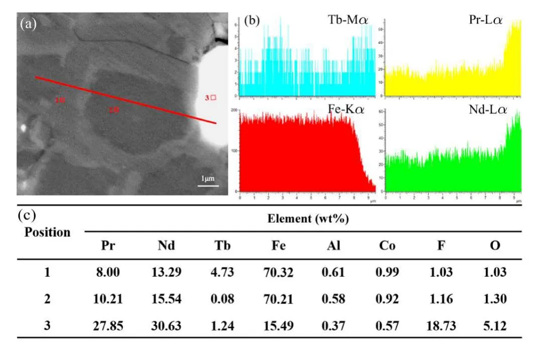
Fig.2.(a)Cross-sectional SEM image of the TbF3-diffused sample.(b)The EDS concentration line profiles of Pr,Nd,Tb and Fe taken from the red line in part(a).(c)The EDS element analysis results for the selected areas in part(a).
To further study the magnetization reversal process in sintered Nd–Fe–B magnets, the domain evolution of thein situKerr domain images with different applied magnetic fields for the annealed sample and the TbF3-diffused sample was observed using a magneto-optical Kerr microscope.Thecaxis of the annealed sample and the TbF3-diffused sample was both in-plane.During observation,the applied magnetic field was ramped manually from +1300 mT to-1300 mT.Figure 3 shows the SEM image and thein situKerr domain images of the annealed magnet at different applied fields.As shown in Fig.3(a), in the annealed magnet, the grain boundary phase is not continuous, and many adjacent hard magnetic grains have direct contact with each other.In the Kerr domain images, the direction of the external magnetic field applied on the sample is antiparallel to the magnetization direction of the magnet.Before observation with the magnetooptical Kerr microscope,the sample was first magnetized with a 5 T applied magnetic field using a pulse magnetizer.After magnetization by a 5 T external field, almost all grains exhibit single-domain state.However,there are still a few grains with multi-domain structure, mainly because of the absence of the grain boundary phase in the polished grains near the surface.During demagnetization,while the applied magnetic field changed to+700 mT nucleation of the first reversed domain was observed, and then the domain state in one grain transformed from the single-domain state to the multi-domain state,as shown in Fig.3(c).In the magnetization reversal process, these low-coercivity multi-domain grains had a higher potential to act as initiators,where the reversed domains would prefer to form.The reversed domains grew and spread through many adjacent grains when the applied field was further decreased to-150 mT,as indicated by the dashed-line ellipses in Fig.3(f).Cascade-type domain propagation was observed and the degree of simultaneous magnetization reversal increased as the applied field was lowered.At an applied field of-300 mT,some grains were inversely saturated.All grains were inversely saturated upon subjecting the sample to a field value of-1200 mT(Fig.3(j)).
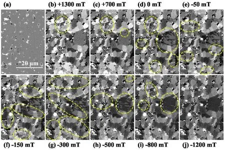
Fig.3.The annealed sample: (a)cross-sectional SEM image and(b)–(j)in situ Kerr domain images at different applied fields.
As shown in Fig.4(a), in the TbF3-diffused sample, the Tb-rich(Nd,Tb)2Fe14B shell structure is well developed in the outer region of the hard magnetic grains.Furthermore,the Ndrich grain boundary phase is more continuous and thicker than that of the annealed sample.During the substitution of Tb for Nd in the Nd2Fe14B grain to form the Tb-rich(Nd,Tb)2Fe14B phase,excess Nd was ejected from the matrix grains and preferred to move to the grain boundaries.As a result,the ejected Nd made the grain boundary phase become more continuous and thicker during the TbF3diffusion process.However, in thein situKerr domain images there is no significant difference between the core and shell areas in a single grain distinguished from the domain contrast because of the low sensitivity of the magneto-optic Kerr microscope.[26]The TbF3-diffused magnet showed a distinct difference in the magnetization reversal and domain propagation process compared with the annealed magnet.In the remanent state, no formation of reversed domains was observed(Fig.4(c)).Unlike the case of the annealed magnet, the first magnetization reversal in the TbF3-diffused magnet appeared at a field of-200 mT,and the magnetic domain state in one grain changed from the single-domain state to the multi-domain state, as marked with dashed-line ellipses in Fig.4(d).This reversal occurred at a larger field than for the annealed magnet.The reverse grains were weak points, from where the magnetization reversal propagated to their adjacent grains.While the applied field further changed to-450 mT, the reverse magnetic domains gradually spread inside the same grains,and the number of grains with reversed domains increased.The reversed domains continued to expand and spread to the adjacent grains at a larger applied field, i.e.,-550 mT (Fig.4(f)), the field at which some grains were reversely saturated compared with the annealed sample.At higher applied fields, cascade domain propagation is observed in a few grains (Figs.4(g) and 4(h)).At the same time, the number of neighboring grains influenced by the simultaneous magnetization reversal in the TbF3-diffused sample was smaller than in the annealed magnet, indicating that the degree of simultaneous magnetization reversal was reduced for the TbF3-diffused magnet with high coercivity.Under the maximum applied magnetic field of the magneto-optic Kerr microscope, all grains were saturated inversely (Fig.4(j)).Compared with Figs.3(a) and 4(a), the microstructure of the magnets changes obviously after TbF3diffusion,therefore,the external field at which the first magnetization reversal and simultaneous magnetization reversal occurred is dependent on the microstructure of the magnets.The Tb-rich (Nd, Tb)2Fe14B shell with a much higher magnetocrystalline anisotropy field formed in the outer region of the hard magnetic grain after diffusion prevented the nucleation and propagation of the reversed domain in the Nd2Fe14B grains.The external magnetic field applied during demagnetization for the TbF3-diffused sample was much larger than that for the annealed magnet,leading to a higher coercivity.
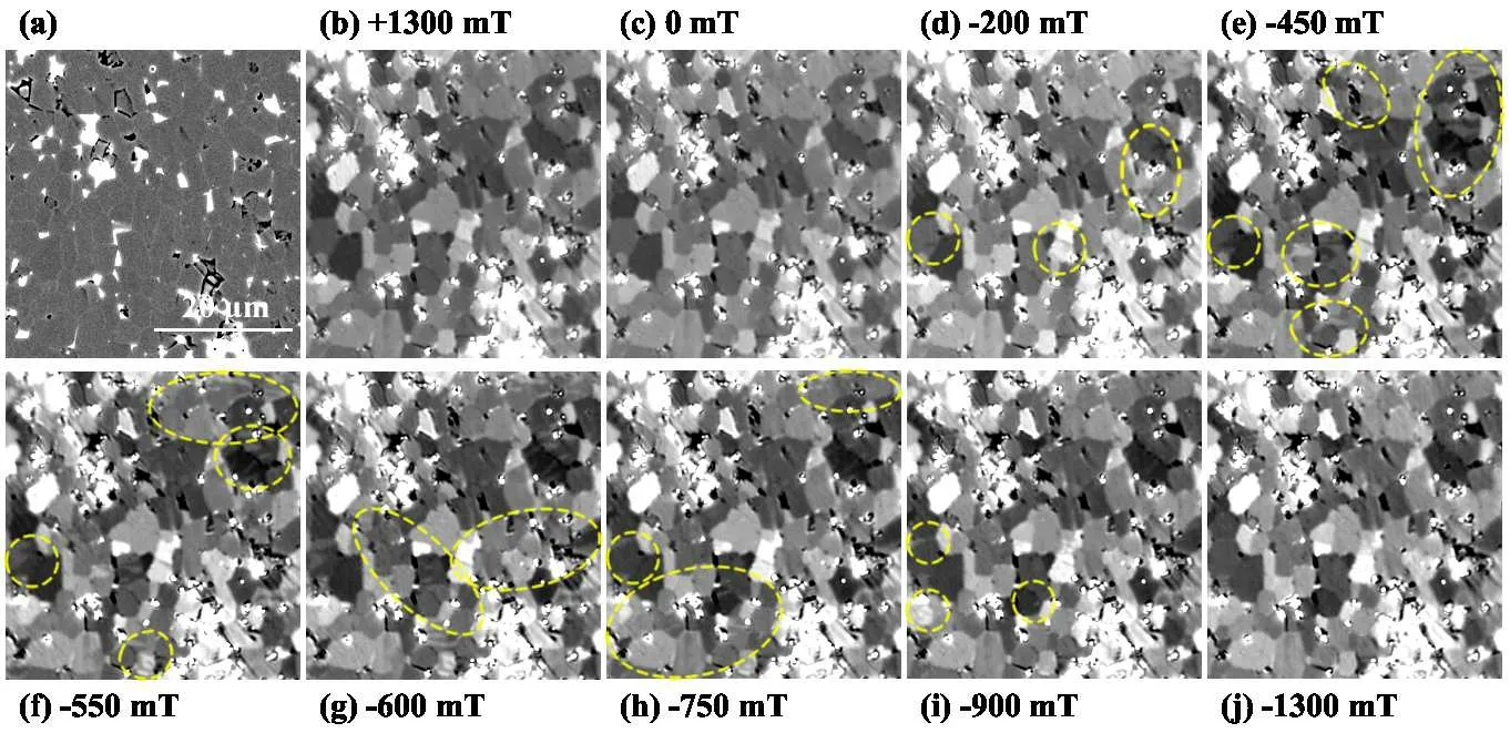
Fig.4.The TbF3-diffused sample: (a) cross-sectional SEM image and(b)–(j)in situ Kerr domain images at different applied fields.
Figure 5 shows the minor loops during demagnetization of (a) the annealed and (b) the TbF3-diffused magnets measured by the step method.The samples were first fully magnetized with an applied magnetic field of 5 T before the demagnetization measurements.In the annealed magnet, when the external magnetic field was near 0 T or the field was less than-1.6 T, the minor loops under each applied field show a similar shape.In these loops, the values of the polarizationJ(Happl) and the remanenceJr(Happl) in the same cycle under the magnetic field(Happl)are almost the same.The same polarization indicates that once the magnetization reversal occurred at the applied fieldHapplit retains the magnetic structure even if the external field drops to zero.However,under an applied field of-1.0 T to-1.6 T,the shape of the loops changes slightly.When the polarization decreased toJ(Happl)with an applied fieldHappl,the polarization obviously increases to the remanence atJr(Happl).The physical explanation for this increase in polarization is that it stemmed from the reproduced domain wall motion(RDWM),JRDWM,in accordance with the results of susceptibility measurements.[27]Some regions returned to multi-domain state while the external field was lower than the demagnetizing field.The reproduced multi-domain regions (RMDR) was generated by nucleation of the magnetization reversal center and the continuous propagation of the reversed region to their neighboring area.In contrast,the minor loops of the TbF3-diffused sample in Fig.5(b) only had small RDWM,especially under an applied field of-2.2 T to-3.0 T,and the increases inJRDWMwere different from those of the annealed sample.
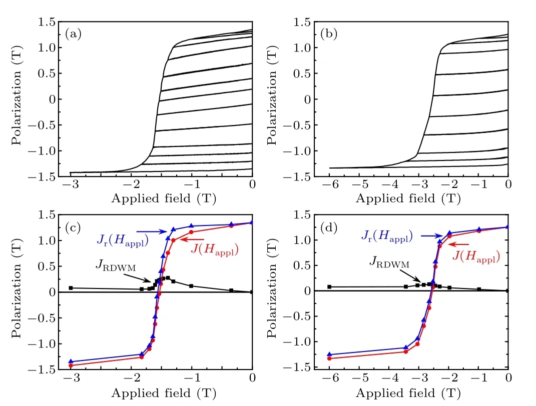
Fig.5.Results of step method measurements in(a)the annealed sample and(b)the TbF3-diffused sample,as well as the separated RDWM using the equation JRDWM =Jr(Happl)-J(Happl) for (c) the annealed sample and(d)the TbF3-diffused sample.
Figures 5(c) and 5(d) show theJRDWMvalues calculated fromJRDWM=Jr(Happl)-J(Happl) in the measured loops,shown in Figs.5(a) and 5(b) for the annealed and TbF3-diffused magnets.TheJRDWMvalues exactly correspond to the polarization change caused by RDWM as indicated in the minor loops.The results show clearly different behavior in the RDWM between the annealed and TbF3-diffused magnets.In the annealed sample,JRDWMwas very small for applied fields from 0 T to-1.0 T,but increased in applied fields below-1.0 T and showed a largeJRDWM.TheJRDWMgradually decreased when the applied field reduced from-1.4 T to about-1.6 T.In contrast to the annealed sample,JRDWMof the diffused sample was small during demagnetization.The maximumJRDWMdecreased with increasing coercivity in the annealed sample(JRDWM=0.29 T)and the TbF3-diffused sample (JRDWM=0.13 T).The fraction of the maximumJRDWMto the saturation polarization(Js),JRDWM/Js,was utilized for defining the maximum volume fraction of the regions where the multi-domain structure returned during demagnetization.The sample which had a big RMDR volume ratio presented a relatively largeJRDWMand small coercivity.This was because when the value ofJRDWM/Jsin the sample was large,the volume ratio of the reproduced multi-domain regions was large; therefore the process of expansion to the surrounding area from the magnetization reversal region was easy.The increased coercivity in the TbF3-diffused magnet can be mainly attributed to the more difficult nucleation of magnetic reversed portions due to the increasedHA.
4.Conclusion
The magnetic properties, microstructure and domain structure of sintered Nd–Fe–B magnets with and without TbF3diffusion by electrophoretic deposition technology were studied.After TbF3diffusion, the coercivity was significantly enhanced from 15.3 kOe to 25.2 kOe.The Tb-rich (Nd,Tb)2Fe14B shell phase in the outer region of the matrix grains was well developed in the TbF3-diffused sample.The first magnetization reversal and the dynamic successive domain propagation process were found using a magneto-optical Kerr microscope.In the annealed magnet, cascade propagation of the reversed domain throughout many neighboring grains was observed.In contrast, the magnetization reversal appeared at a larger applied field and the degree of simultaneous magnetization reversal decreased in the TbF3-diffused magnet.By the step method, domain wall motion was observed, and domain wall motion was generated in the RMDR during demagnetization after full magnetization.The maximumJRDWMdecreased with increasing coercivity, and varied fromJRDWM=0.29 T for the annealed sample toJRDWM= 0.13 T for the TbF3-diffused sample.The increased coercivity in the diffused sample is mainly attributed to the more difficult nucleation of the magnetic reversed region owing to the enhancement of the magneto-crystalline anisotropy field by Tb diffusion.
Acknowledgments
Project supported by the National Natural Science Foundation of China (Grant No.52101238), the “Pioneer” and“Leading Goose” Research and Development Program of Zhejiang (Grant No.2021C01190), and Major Project of Ningbo Science and Technology Innovation 2025 (Grant No.2020Z046).
杂志排行

Chinese Physics B的其它文章
- Dynamic responses of an energy harvesting system based on piezoelectric and electromagnetic mechanisms under colored noise
- Intervention against information diffusion in static and temporal coupling networks
- Turing pattern selection for a plant–wrack model with cross-diffusion
- Quantum correlation enhanced bound of the information exclusion principle
- Floquet dynamical quantum phase transitions in transverse XY spin chains under periodic kickings
- Generalized uncertainty principle from long-range kernel effects:The case of the Hawking black hole temperature