Rotor performance enhancement by alternating current dielectric barrier discharge plasma actuation
2023-03-09GuangyinZHAO赵光银ChangWANG王畅YongdongYANG杨永东GuoqiangLI李国强andZheyuSHI史喆羽
Guangyin ZHAO(赵光银),Chang WANG(王畅),Yongdong YANG(杨永东),Guoqiang LI(李国强)and Zheyu SHI(史喆羽)
China Aerodynamics Research and Development Center,Low Speed Aerodynamics Institute,Mianyang 621000,People’s Republic of China
Abstract An experimental system was established to explore the plasma flow control effect for helicopter rotors in hover mode.With the plasma actuator applied at the leading edge of the rotor blades,alternating current dielectric barrier discharge(AC-DBD)plasma actuation was generated by a sinusoidal AC high-voltage generator.By direct force measurement,the influence of actuation parameters on the aerodynamic performance of the rotor was investigated at a tip Reynolds number of 1.7×105.AC-DBD actuation can delay the blade stall to more than 3° with a 20%increase of about in the thrust coefficient at the post-stall pitch.At a constant motor power driving the rotor,AC-DBD actuation could reduce the rotor’s torque at the stalled pitch and increase the rotational speed of the rotor.Also,AC-DBD actuation could maintain a relatively high hover efficiency of the rotor at large collective pitches.In a wide range of actuation parameters,AC-DBD plasma actuation could improve the rotor’s aerodynamic performance at large blade pitches.High-speed photography of the tuft motion on the blade’s upper surface showed that AC-DBD plasma actuation could promote the reattachment of the blade’s separation flow.
Keywords:rotor,flow control,plasma actuator,dielectric barrier discharge,force measurement
1.Introduction
When a helicopter is flying forward,the retreating blade is working at large angles of attack to maintain aerodynamic balance with the forwarding blade.The greater the forwarding flight speed,the larger the angle of attack of the retreating blade.Thus,the rotating blades can easily enter a dynamic stall state,especially in the case of a helicopter flying at a high speed or with a heavy load.
Flow separation or dynamic stall occurring on the rotor blades is an important limiting factor for helicopter performance.It will lead to an increase in rotor power requirement,blade flutter and a reduction in the rotor/body coupling dynamic stability of the helicopter,limiting its flight envelope[1,2].If the flow separation of the helicopter’s rotors is restrained,the collective pitch of the rotor can be further increased and the maximum available lift force can be also enhanced.
Compared with a fixed wing,flows around a rotor blade are more complex and unsteady.The incoming flow velocity and angle of attack for each blade is changing in forward flight,which requires the flow control method to have the function of adjusting actuation parameters in real time.Common flow control methods[3]and the progress of their development for airfoil dynamic stall control are reviewed in[4,5].
Plasma actuation mainly uses a high voltage acting on a plasma actuator to break down local gas,and the charged particles move under the electric field,often accompanied by the emission of light and heat.Typical plasma actuations usually include surface-arc actuation mainly used for shock control,plasma synthetic jets mainly used for high-speed control and dielectric barrier discharge(DBD)actuation mainly used for low-speed separation control.Compared with other flow control techniques,a plasma actuator has the advantages of very short response time,simple construction,low weight,wide frequency bandwidth control authority and low energy consumption.
The use of DBD plasma actuators for flow control has been extensively studied over the last 15 years.However,research on surface DBD plasma actuation for separation control has mainly focused on static airfoils.Research into DBD plasma actuation for dynamic stall control started 15 years ago[6],mainly for two-dimensional oscillating airfoils[7–9].However,flow control of the rotor blade stall has not been widely studied.
A team at Northwestern Polytechnical University in China carried out preliminary flow field measurements on plasma flow control of rotors and obtained the flow field changes before and after plasma actuation[10].Starikovskiyet alused nanosecond pulsed surface DBD actuation to increase the lift of a rotor in hovering mode[11].Within the actuation frequency range of 300–2000 Hz,the maximum lift coefficient could be increased by 50% at most.
Recently,DBD plasma actuation was used for leadingedge separation control on a 300 kW rotor with a blade chord length of around 1 m at a Reynolds number(Re)of∼1.6×10⁶.It was found that the power coefficient improved under actuation at low tip speed ratios[12].Greenblattet alapplied pulsed plasma actuation for rotor performance enhancement,and the effect of pulse-modulated actuation was evaluated at tipRe=1.0×10⁵and 1.5×10⁵[13].The flow control effect showed a mild sensitivity to reduced frequency and a small effect of the duty cycle(DC).
So far,there have been only preliminary investigations on rotor flow control using DBD plasma actuation.The influence of actuation parameters needs to be further revealed.In this work,a test system for a plasma-assisted rotor is established,and the influence of plasma actuation parameters on the aerodynamic performance of the rotor in a hovering state is investigated.
2.Experimental setup
The test was carried out on the Φ1.5 m rotor test rig of the China Aerodynamics Research and Development Center.The rotor test rig system is composed of a rotor hub,a six-component balance,direct current speed-regulating motor,etc.The rotor has a 1400 mm blade span and is powered by a direct current electrical motor with a rated power of ∼4.4 kW.The maximum rotational speed of the rotor is about 2200 r min−1.The plasma flow control system mainly consists of rotor blades with plasma actuators,an electrical slip ring for a highvoltage power supply,a high-voltage AC power supply,a force balance and an aerodynamic data acquisition system,as shown in figure 1.
After adjusting the pitches each time,the aerodynamic data were acquired when the balance data reached dynamic stability.For each test state,during a period of 84 rotations of the rotor,the balance data and the rotation speed were acquired synchronously under the 64 per revolution triggers of the encoder azimuth sign.Since the rotor is in a hovering state,aerodynamic data for 84 laps are processed on average.The final time-average data are used to calculate the thrust coefficient and torque coefficient of the rotor.The dimensionless thrust coefficientCTand torque coefficientCMyare calculated by
where Ω is the rotor blade angular velocity,nis the rotation speed,Ris the rotor radius,ρ is the air density,Tis the thrust of the rotor model andMyis the torque of the rotor model.
The test employed a two-blade rotor made of fiber-reinforced resin matrix composite material.The rotor blades have a section of CRA312 airfoil along the whole blade span and a rectangular blade planform.The chord length of the blade is 75 mm,and the rotor radius(calculated from the rotation center)is 700 mm.The blades are designed in a linear torsion with a twist angle from the root to the tip of −8°.The collective pitch(θ0.7or α)of the rotor refers to the pitch at 70%of the rotor radius.
The plasma actuation system consists of a DBD actuator,a sine waveform AC power supply and an electric parameter measurement system.The asymmetric DBD actuator consisted of electrodes and dielectric material,which were attached to the leading edge of each blade.A 0.2 mm thick copper tape was used for the electrodes,and a 0.12 mm thick Kapton tape was the dielectric material.The two electrodes separated by the dielectric layer were glued to the barrier layer with an inner gap of 0 mm.The anode was exposed to the atmospheric environment and the cathode was encapsulated under the dielectric material.
DBD actuators can be placed at various places on the blade’s surface.In the present study,the actuator is arranged at the leading edge of the blade from 0.2Rto 0.95Rin its spanwise direction.Figure 2 gives the details of the location of the DBD actuator.Plasma actuation was generated on the pressure side of the blade and the direction of induced airflow is consistent with the direction of the incoming flow.At high angles of attack,the perturbation generated by the plasma actuation propagated along the leading-edge surface to the suction side.
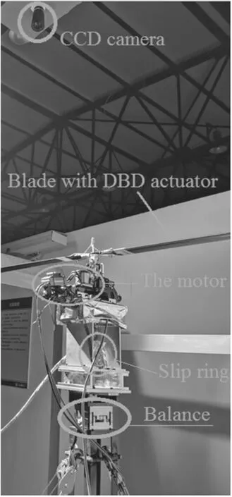
Figure 1.The overall test system.
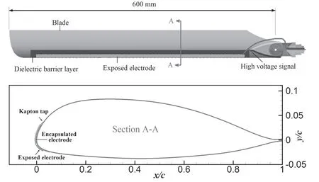
Figure 2.The rotor’s airfoil section with a DBD plasma actuator.

Figure 3.(a)Discharge image and(b)the discharge voltage–current waveforms of the DBD actuator on the blade(fc=5.145 kHz,Vpp=8.5 kV).

Figure 4.Repeatability of two measurements of the baseline aerodynamic coefficients of rotors at different pitches.

Figure 5.Changes of(a)thrust coefficient and(b)torque coefficient as a function of pulsed frequency.

Figure 6.Time history of thrust coefficients and rotational speed variation under different actuation frequencies(θ0.7=19.9°).

Figure 7.Dependence of thrust coefficients and torque coefficients on the duty cycle(DC)of unsteady actuation.
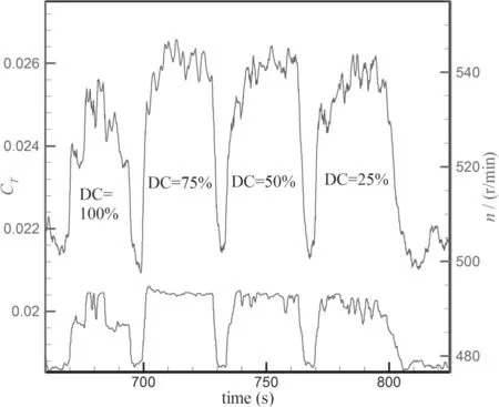
Figure 8.Time history of thrust coefficients and rotational speed variation under different actuation duty cycles(DC)at θ0.7=21.1°.

Figure 9.Influence of actuation parameters on hover efficiency.(a)Influence of actuation frequency when the duty cycle(DC)=50%and Vpp=8.5 kV.(b)Impact of DC when fp=540 Hz and Vpp=8.5 kV.

Figure 10.Tuft-based flow visualization of the blade(θ0.7=21.1°):(a)baseline,(b)pulsed plasma actuation at DC=50%,fp=540 Hz.
The AC power supply had a range of output peak-peak voltages(Vpp)of 0–20 kV and a carrier frequency(fc)range of 5–20 kHz.As the actuator was activated,the discharge voltage and current were measured by a four-channel DPO4104 Tektronix oscilloscope,a Tektronix P6015A highvoltage probe,and a current probe(TCP0030).A typical profile for the discharge voltage(Vpp)–current(I)signal is shown in figure 3.The percentage of time when the AC voltage is on is called the DC;this is controllable within the range of 5%–99%.The modulation pulse frequency can be continuously adjustable from 1 to 1000 Hz.When the pulsemodulated voltage was applied to the DBD actuator,the actuation is cycled on and off with an unsteady period,thus,unsteady plasma actuation is generated with a series of unsteady vortices moving along the wall surface.When DC=100%,the actuator is driven by continuous AC voltages and steady plasma actuation can be generated with a tangential jet along the wall[14].
To conduct the AC power to the DBD actuator on the rotating blades,the test rig was additionally equipped with a three-channel electrical slip ring.Each channel can withstand voltages up to 15 kV and current up to 10 A.The contact resistance of each channel is about 0.01 Ω,which allows trusty delivery of high-voltage pulses from the AC power supply to the DBD actuator on the rotating blades.The discharge signal is stable as the speed is gradually increased,indicating that the conductive slip ring is reliable.
3.Analysis of test results
3.1.Baseline performance
In static airfoil separation control,AC-DBD actuation can control flow separation up toRe=2.3×10⁶corresponding to Mach 0.4[15].For helicopters,the typical flow velocity over the retreating blades is of the order of 100 m s−1(Mach0.3)withReof the order of 106.This typical flow condition is within the controllable range of AC-DBD actuation.In the current test,considering the stable rotational speed of the rotor test rig and the voltage tolerance of the slip ring,a rotational speed ofn=550 r min−1was selected,corresponding to a blade tip speed of about 40 m s−1and tipRe=1.7×10⁵.
Firstly,the baseline aerodynamic performance of the rotor was measured with the plasma actuation turned off.The collective pitch θ0.7of the blade was granularly increased to obtain the stall angle.At each collective pitch,the thrust and torque data are acquired by the box balance,and the dimensionless results are shown in figure 4.
The overall uncertainty in both the thrust and the torque data was estimated by repeating the force measurement of the rotor twice,which showed that the force measurements were stable and reliable,especially at high angles of attack.However,the repeatability is relatively poor at low angles of attack,mainly due to the small aerodynamic load of the blades at low angles of attack.
The thrust coefficientCTmaintains a linear growth before the stall pitch,while the torque coefficientCMypresents a non-linear growth trend.However,when the collective pitch exceeds 17°,the thrust coefficient decreases and the corresponding torque coefficient increases sharply,indicating that the blade stall phenomenon occurs above this pitch.
3.2.Parametric study
The parametric study was conducted under a constant motor powerPm,corresponding to the initial conditions ofn=550 r min−1with θ0.7=−1°.
In the tests,two patterns of actuation(steady actuation and pulsed actuation)were tested.With the carrier frequency fixed at 5.145 kHz during modulation,the influence of pulse frequencyfpand DC on the control effect was studied.
3.2.1.Influence of pulsed actuation frequency.In most investigations on plasma flow control,it is found that leadingedge plasma actuation has little effect on the airfoil’s lift and drag coefficients before the stall.So,the flow control effect was investigated only near the stalled pitches.The influence of the pulsed actuation frequency on the control effect was firstly studied.
For an airfoil with a constant chord lengthcin a freestreamU∞,the reduced actuation frequency is almost defined asF+=fp×c/U∞.For a rotor blade in a rotational state,the velocity magnitude relative to the blade varies with the radiusrand rotational speed Ω.
Thus,the reduced frequency at radiusrcan be defined as
At a constant rotational speed,Ui(r)varies with the pitch.Here,we may not be able to obtain an accurate value ofUi(r).At a constantfp,F+changes with the radiusr.In this paper,under the assumption thatUi(r)is much lower than ΩR,and for convenience,we defined a reduced frequency based on the flow conditions at the middle of the blade,namely,
With the actuation voltageVpp=8 kV and DC=50%,the pulsed actuation frequencyfpwas adjusted to 67,135,270,400,540,670,800 and 1000 Hz,respectively.A rotational speed ofn=550 r min−1corresponds to aUmidof 20 m s−1;thus the corresponding reduced pulsed actuation frequencyF+=0.25,0.5,1.0,1.5,2,2.5,3 and 3.75,respectively.The changes in thrust coefficients and torque coefficients with and without plasma actuation are shown in figure 5.
Without actuation,the blades achieve their maximal thrust coefficient at θ0.7=16.7°–18.9°.Further increase of θ0.7leads to severe flow separation of the blades and decrease in the thrust coefficients.When the actuator is working at post-stall pitches,the thrust coefficient is effectively increased and AC-DBD actuation keeps the thrust coefficient at a relatively high level compared with the plasma off case.
In terms of torque coefficients,before the stall pitches(e.g.θ0.7=16.7°),the torque coefficient of the rotor is almost unchanged under the actuation.For post-stall pitches,the torque of the rotor is reduced noticeably for the actuated cases compared with the baseline,and the stall pitch is greatly delayed up to more than 3°.At θ0.7=21.1°,the thrust is increased by about 20%,and the torque is reduced by about 27.4%.
The changes in thrust and torque coefficients indicate that AC-DBD plasma actuation can effectively increase the payload and extend the flight envelope of the rotor.
In a certain range,the influence of actuation frequency is obvious,and the control effect is relatively weak whenfpis less than 270 Hz.From the aerodynamic coefficients,the control effects are very similar in the actuation frequency range offp=270–670 Hz.To make the graph easy to read,the results atfp=270 and 400 Hz are not drawn in figure 5.Further,we select θ0.7=19.9°to observe the time history of thrust coefficients and the changes in rotational speed at different actuation frequencies,as shown in figure 6.The thrust coefficients with increasing effect correspond tofp=1000,800,670,540,400,270,135 and 67 Hz from left to right in figure 6(the red line).
Firstly,we can confirm that different actuation frequencies have achieved obvious control effects compared with the plasma off case.From the comparison of flow control effects under differentfp,the relatively more obvious control effect is achieved atfp=670 and 540 Hz.
When motor powerPmis constant,we knowPm=A×My×n,whereAis a constant.When torqueMydecreases,rotational speednwill increase.Under the same motor powerPm,the decrease in the blade’s drag at different plasma actuation frequencies can also be observed from the increase of the rotational speed.As shown in figure 6(the blue line),the changes in rotational speed are obvious with and without actuation.The rotational speed without plasma control isn=493 r min−1,and the average rotational speed increases ton=500 r min−1with actuation.
3.2.2.Impact of duty cycle.In addition to the pulse frequency,DC is also an important parameter of unsteady actuation.The smaller the DC,the stronger the non-stationary of the actuation.On the contrary,the larger the DC,the more stable and steadier the actuation.When DC = 99%,it can already be considered a steady actuation.
With the actuation frequencyfp=540 Hz and the actuation voltageVpp=8.5 kV,the influence of DC at DC=25%,50%,75% and 100% on the flow control effect was tested.The changes in thrust coefficients and torque coefficients before and after plasma actuation are shown in figure 7.
On the whole,in the tested DCs,obvious improvements in thrust coefficients and torque coefficients have been achieved compared with the plasma off case.
Except for the effect at DC=100%,which is slightly weaker,other DCs seem to make only a limited difference to the flow control effect.The time history of the thrust coefficients and rotational speed variations under different DCs at θ0.7=21.1° was tracked,as shown in figure 8.The thrust coefficients with the increasing effect correspond to DC=100%,75%,50%,and 25% from left to right in figure 8(the red line).
For the rotor driven by a constant motor power,the rotor’s thrust and rotational speed change obviously under plasma actuation with different DCs.At the stall pitch θ0.7=21.1°,plasma actuations with DC=50% and 75%give the most obvious improvements in the thrust force,and the rotational speed is most stable.
When the motor power driving the rotor is constant,an increase in the blade’s drag will decrease the rotational speed,especially in stalled conditions.When AC-DBD plasma actuation is applied and the flow separation is restrained,the pressure drag on the blade is reduced,the rotor speed is further increased and the rotor thrust is also improved.Therefore,plasma actuation has the potential for application in energy-saving and separation control of helicopter retreating blades.
The effect of plasma actuation on the hover efficiency is also analyzed.The hover efficiency of the rotor is
Figure 9 shows the changes in hover efficiency with and without plasma actuation.At the stalled collective pitches,the hover efficiency is significantly improved by AC-DBD plasma actuation compared with the plasma off case.At the same time,the changes in η are related to the parameters θ0.7andfp.At a slight-stall pitch(θ0.7=18.9°),differentfpcan achieve a relatively consistent improvement in η.At deepstall conditions(θ0.7=19.9°,21.1°),the influence offpis obvious.Anfpvalue of540 Hz seems to be the threshold frequency,and the hover efficiency is more pronounced whenfp≥540 Hz;a further increase in actuation frequency had only a minor effect on improvement of η.
At slight-stall pitches(θ0.7=18.9°,19.9°),the four tested DCs produce very similar changes to the hover efficiency.However,a marked difference was observed at θ0.7=21.1°,with only a very limited increase in the hover efficiency under steady actuation(DC=100%).
3.3.Flow visualization
To further understand the effectiveness of plasma actuation in modifying the flow,a high-speed camera was used to monitor flow patterns of the surface tuft in real time.A series of surface tuft-based flow visualizations were obtained on the outer 3/5 of the blade.A tuft of 402 polyester cotton sewing thread with a diameter of approximately 0.1 mm and a length of approximately 20 mm was evenly pasted on the upper surface along the spanwise direction,The tuft has a fasttracking ability to intuitively and dynamically display the flow separation region on the upper surface of the blade.The layout of the tuft measurement was shown in figure 1.
A lamp(EF-200W LED)was placed on a stand beside the test rig to illuminate the tufts.At an exposure time of 50 ms and a sampling frequency of 2000 Hz,the camera recorded the video image of the tufts for 2 s for each test case.
As the thread can only qualitatively display the flow patterns with and without plasma actuation,the detailed differences in the flow field under different actuation parameters cannot be distinguished.So,in addition to the plasma off case(figure 10(a)),only one controlled flow case at DC=50% andfp=540 Hz is presented here(figure 10(b)).The tuft states for other actuation parameters were very similar to figure 10(b).
For the baseline,the free ends of the tufts showed obvious lateral swing and upstream swing,indicating that there is obvious flow separation on the upper surface of the blades.
When plasma actuation was activated,those same tufts consistently deflected downstream and there was no obvious wobble,indicating that flow separation was well restrained by plasma actuation.However,under plasma actuation,the tufts near the blade tip still had a certain swing,and their orientations varied from image to image,indicating that it was difficult for AC-DBD actuation to restrain tip separation of the blade.
4.Conclusions
To explore plasma flow control technology and its effect on helicopter rotors,a rotor plasma flow control test system was established in this work.Arranged at the leading edge of the blade from 0.2Rto 0.95R,a DBD plasma actuator driven by sinusoidal AC high voltages was used for plasma actuation.By direct force measurement,the influence of actuation parameters on the aerodynamic performance of the rotor in a hovering state was studied at a tipReof 1.7×10⁵.The main conclusions are as follows:
(1)Preliminary test results indicate that AC-DBD plasma actuation at the leading edge of the blade can produce a significant increase in the thrust,delay blade stall,improve the maximum thrust coefficient of the rotor and improve the hover efficiency after stall at a constant power to the motor.
(2)Under a constant motor power,plasma actuation can reduce the rotor torque and increase the rotational speed at post-stall pitches.Compared with the steady actuation case,unsteady actuation is more efficient in aerodynamic improvement at large pitches.
(3)Tuft-based flow visualizations obtained by a high-speed camera show that plasma actuation promotes reattachment of the flow separation of the blade’s upper surface.
From the control effect,AC-DBD actuation can improve the aerodynamic characteristics of the rotor in a hovering state,and also shows its potential ability to control the dynamic stall of the retreating blades in a helicopter.
Unlike plasma flow control on the fixed-wing or 2D static airfoil,the optimal actuation frequency range obtained in this study is relatively wide.Rotation of the blades leads to a large difference in flow velocity near the root of the blade and near its tip,which makes it difficult to optimize the pulsed actuation frequency along the whole span of the blade.Therefore,it may be a good choice to arrange distributed actuators spanwise and apply different actuation frequencies for each section of the blade.
杂志排行

Plasma Science and Technology的其它文章
- Development of miniaturized SAF-LIBS with high repetition rate acousto-optic gating for quantitative analysis
- Improving plasma sterilization by constructing a plasma photocatalytic system with a needle array corona discharge and Au plasmonic nanocatalyst
- A nanoparticle formation model considering layered motion based on an electrical explosion experiment with Al wires
- Focused electron beam transport through a long narrow metal tube at elevated pressures in the forevacuum range
- A study of the influence of different grid structures on plasma characteristics in the discharge chamber of an ion thruster
- High-resolution x-ray monochromatic imaging for laser plasma diagnostics based on toroidal crystal