Analytical and Experimental Studies on Wave Scattering by a Horizontal Perforated Plate at the Still Water Level
2022-12-27HEShuyueZHAOYangLIUYongandLIHuajun
HE Shuyue , ZHAO Yang , , LIU Yong , and LI Huajun
1)Shandong Provincial Key Laboratory of Ocean Engineering, Qingdao 266100, China
2)College of Engineering, Ocean University of China, Qingdao 266100, China
Abstract This research investigates water-wave scattering via a horizontal perforated plate fixed at the still water level through analytical studies and physical model tests. The velocity potential decomposition method is combined with an efficient iterative algorithm to develop an analytical solution in which the quadratic pressure drop condition is imposed on the horizontal perforated plate.The analytical results are in good agreement with the results of an independently developed iterative boundary element method(BEM)solution. Experimental tests are carried out in a wave flume to measure the reflection coefficient and transmission coefficient of the horizontal perforated plate, and the analytical results agree reasonably well with the experimental data. The influence of various structural parameters of the horizontal perforated plate on the hydrodynamic parameters of reflection coefficient, transmission coefficient, energy-loss coefficient, and wave force are analyzed on the basis of the analytical solution. Useful results for the practical engineering application of horizontal perforated plates are also presented.
Key words horizontal perforated plate; still water level; analytical solution; quadratic pressure drop condition; physical model test
1 Introduction
Horizontal perforated plates, a simple structure that can dissipate wave energy effectively, are widely used for coastal protection. These plates possess the advantages of low construction cost and bearing low wave force and are usually placed near the still water level to achieve good wave energy dissipation effects. The hydrodynamic characteristic of submerged horizontal perforated plates has been well studied in previous research.
Studies on the interactions of waves with submerged horizontal perforated plates mainly adopt theoretical method based on linear potential theory and physical model tests based on similarity theory. Chwang and Wu (1994)analytically studied the wave scattering of a horizontally submerged porous disk by using the matched eigenfunction expansion method and found that the behavior of the porous disk is similar to that of a wave absorber; the authors also determined that the porous disk shows better behavior when it has a larger radius. Yu (1995)proposed a linear boundary condition for perforated plates by introducing the complex porous-effect parameter, which considers the effects of the inertial and resistance forces of the perforated plate. Besides, the boundary condition of Yu(1995)was verified by the collected experimental data. Yip and Chwang (1998)analytically investigated the feasibility of using a pitching perforated plate to control water waves actively and found that the porosity (ε)of the plate,rather than its pitch, has a certain effect on the phases of radiation and wave scattering. Liu and Li (2011)used the velocity potential decomposition technique to analyze water-wave motion over submerged horizontal perforated plate breakwaters and, thus, avoiding the need to solve complex water-wave dispersion relations. Cho and Kim (2013)extended the study of Liu and Li (2011)to oblique waves and conducted a series of experiments to validate the analytical solution. The concept of dual submerged horizontalplate breakwaters was also proposed to improve the wave energy dissipation efficiency of the horizontal- plate breakwater. Liuet al.(2008)developed analytical solutions for the submerged breakwater featuring an upper horizontal porous plate and a lower horizontal solid plate and indicated that the hydrodynamic performance of the breakwater might be enhanced if the below one is perforated.Kee (2009)optimized dual submerged horizontal-plate breakwaters by slightly inclining the lower solid plate. The hydrodynamic characteristics and structural design parameters of dual submerged horizontal perforated plates were then systematically studied (Liuet al., 2012; Choet al.,2013; Liu and Li, 2014). Several scholars (Fanget al.,2017, 2018; Huet al., 2019)have studied multi- layer horizontal perforated plate breakwaters; the results of such research indicated that the lower plate obstructs the vertical motion of the fluid and that the total wave force increases with an increasing number of layers.
Previous studies showed that the wave dissipation performance of a horizontal perforated plate is mainly affected by its submergence depth and structural geometric parameters. As the horizontal perforated plate approaches still water level, its wave energy dissipation efficiency improves (Cho and Kim, 2013; Jinet al., 2014; Heet al.,2021). Most horizontal perforated plates are installed below the water surface, and only a few studies have considered that it is at the still water level. Zhaoet al. (2010)studied the interactions between waves and a porous cylinder with an inner horizontal perforated plate by using theoretical analysis and experiment model tests. The authors found that the inner plate eliminates the sloshing mode in the case of wave exciting surge force and pitch moment and that a perforated plate located at the still water level could effectively increase the efficiency of wave dissipation. Cho (2013)developed an analytical solution of the horizontal perforated plate at the still water level based on the linear boundary condition, but the results obtained were not verified experimentally. Perforated plates installed at the still water level demonstrate good wave energy dissipation performance, but further systematic studies are necessary before the concept can be adopted in practical engineering.
In the present study, theoretical and experimental methods are adopted to investigate water-wave scattering on a horizontal perforated plate at the still water level to offer a valuable reference for practical structural design. Different from the analytical study of Cho (2013), the analytical solution developed in this work is based on the quadratic pressure drop condition on the perforated plate at the still water level. The beauty of the quadratic pressure drop condition is that it can directly consider the influence of incident wave heightHon wave energy dissipation. In Section 2, the mathematical model is formulated and the corresponding analytical solution is solved using the velocity potential decomposition method with iterative calculations. The physical model tests are introduced in Section 3. In Section 4, the convergence of the analytical solution is examined; the analytical solution is also compared with an independently developed iterative boundary element method (BEM)solution and the experimental results. In Section 5, a discussion of the results is presented, and the influences of different structural parameters on the reflectionCR, transmissionCT, and energy-lossCEcoefficients and wave force of the plate are analyzed. Finally, the main conclusions of this study are summarized in Section 6.
2 Analytical Solution
A sketch of ideal oblique wave interactions with a horizontal perforated plate fixed at the still water level is shown in Fig.1. The horizontal perforated plate with widthbis located in the ocean with constant depthh, and the plate porosity isε. A 3D Cartesian coordinate system meeting the right-hand rule is developed to describe the problem;here, the originois set on the wave-side end of the plate.Thex-yplane is located at the still water level, and thez-axis is oriented toward the positive vertical direction.Because the plate length in they-direction is much larger compared with the incident wavelength, it is assumed to be infinite in the mathematical model. Moreover, the plate thicknessδis very small compared with the water depth and incident wavelength. Small-amplitude and time- harmonic oblique waves withHand angular frequencyωpropagate at an angleθrelative to the positivex-axis. The components of the wave numberk0in thex- andy-directions can be written ask0x=k0cosθandk0y=k0sinθ, respectively. The whole fluid domain is divided into three sub-regions: sub-region 1, which is the fluid domain at the left-hand side of the plate; sub-region 2, which is the fluid domain beneath the plate; and sub-region 3, which is the fluid domain at the right-hand side of the plate.

Fig.1 Sketch of the ideal interaction of waves with a horizontal perforated plate fixed at the still water level.
The fluid is assumed to be inviscid and incompressible,and its motion is irrotational. The fluid motion in each subregion can be specified by the velocity potential Φ(x,y,z,t).The velocity potential of time-harmonic obliquely incident waves can be written as

where Re[ ] denotes the real part of the argument,φ(x,z)denotes the spatial distribution of the potential function on thex–zplane, and
The complex spatial velocity potentialφ(x,z)in each sub-region satisfies the modified Helmholtz equation:

where the subscriptjdenotes the velocity potential in subregionj.
At the still water level, the potentials satisfy the free surface condition:

whereK=ω2/g.
At the bottom of the water, the potentials satisfy the impermeable condition:

The waves must be outgoing at far fields and satisfy the condition:

whereφRis the velocity potential of reflected waves.
In the analytical study, the perforated plate must adopt a suitable boundary condition to incorporate the wave energy dissipation and phase change induced by the perforated plate reasonably. Some scholars (Cho and Kim, 2000;Zhaoet al., 2010)have proposed linear pressure drop boundary conditions for horizontal perforated plates at the still water level. The wave energy focuses on the free surface and is related toH. The quadratic pressure drop condition, which directly considers the effect ofHon wave energy dissipation, can be derived and utilized to study the hydrodynamic characteristics of the perforated plate at the still water level.
The quadratic pressure drop condition considering the wave energy dissipation and phase shift of the submerged horizontal perforated plate is written as (Molin, 1992; Molin and Remy, 2015; Liu and Li, 2017):

where the discharge coefficientμand blocking coefficientCrespectively denote the resistance and inertial effects of the perforated plate on the fluid motion; the values of these parameters should be carefully calculated in prior to obtain reasonable solutions. The discharge coefficientμis relevant to several parameters, includingε, the geometry of the openings, and the Reynolds number, and its value is usually obtained through experimentation (Molin, 1993).The blockage coefficientCdepends on the geometry of the structure and is independent of the wave characteristics(Newman, 1969; Tuck, 1975). An empirical formula forCdeveloped by Suhet al. (2011)is adopted in this paper as follows:

The fluid flow above the horizontal plate should meet the linear free surface condition:

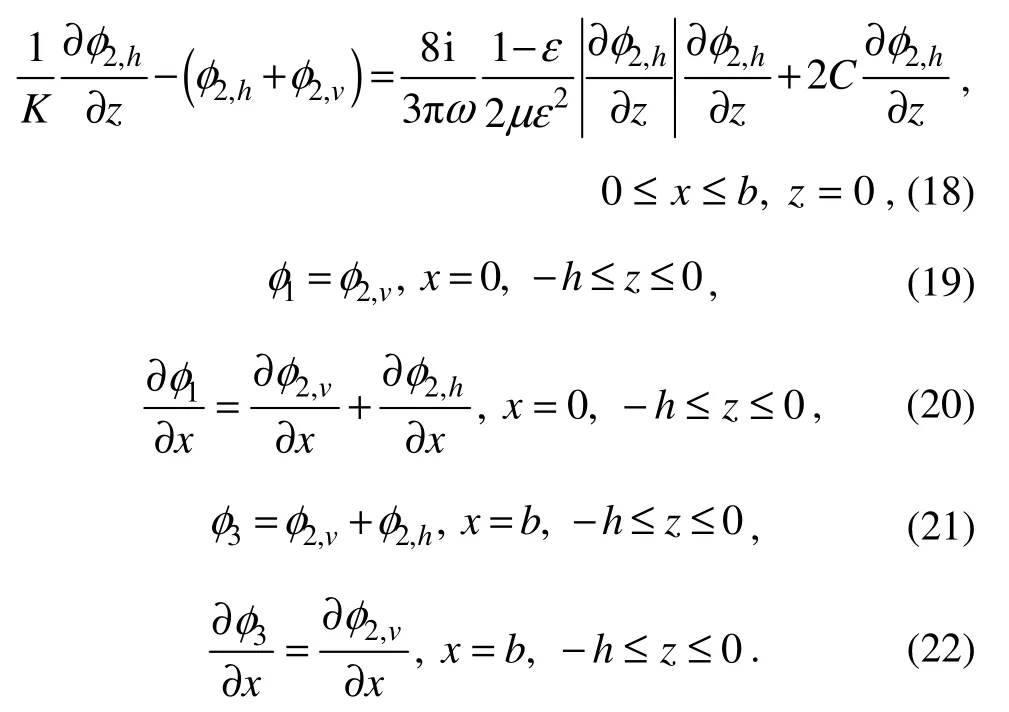
Following the introduction of Eq. (7)into Eq. (5), a new quadratic pressure drop boundary condition for a perforated plate located at the still water level is obtained:

Eqs. (1)- (4), together with Eq. (8), describe the complete boundary value problem for oblique wave scattering by a horizontal perforated plate fixed at the still water level.In the present study, the boundary value problem is solved by the velocity potential decomposition method (Liu and Li, 2011; Liuet al., 2012; Fanget al., 2017; Heet al., 2021)with iterative calculations. Besides the preceding boundary conditions, the following matching conditions between adjacent sub-regions should be adopted in the analytical calculation:

The velocity potentials in sub-region 2 are decomposed into two components:

where the subscriptsvandhindicate that the corresponding artificial velocity potentials in region 2 are derived by the method of separation of variables along the vertical and horizontal directions, respectively.
The decomposed velocity potentials still satisfy the modified Helmholtz equation and the corresponding boundary conditions:

Therefore, Eqs. (8)- (12)can be rewritten as:
The velocity potentials in sub-regions 1 – 3 satisfying the modified Helmholtz equation and the boundary condition in Eqs. (2)- (4)and Eqs. (14)- (17)can be derived as:

In Eqs. (23)- (26),Rn,An,Bn,Cn, andTn(n= 0, 1, 2, ···)are unknown complex expansion coefficients to be calculated, andZn(z),Wn(x)andXn(z)(n= 0, 1, 2, ···)are eigenfunctions as follows:

These eigenfunctions are all orthogonal in their own intervals and can be used to simplify the calculations. The wave numbersknx,βnz, andμnx(n= 0, 1, 2, ···)in Eqs. (23)- (26)satisfy the following relationships:


The matching conditions between adjacent sub-regions described in Eqs. (18)- (22)should be used to determine unknown coefficients in the velocity potential expressions.For example, substituting Eqs. (23)and (25)into Eq. (18),multiplying both sides of the new equation by the eigenfunctionXm(z), integrating with respect tozfrom -hto 0,using the orthogonal relation, and then truncatingmandntoNyields:

The matrix coefficients in Eq. (39)are listed in the Appendix.
Similarly, substituting Eqs. (23)- (26)into Eqs. (19)-(22)and conducting algebraic operations similar to those described above yields:

The matrix coefficients in Eqs. (40)- (43)are also listed in the Appendix.
All unknown expansion coefficients can be determined by simultaneously solving Eqs. (39)- (43). Eq. (43), including the coefficients (A.11)and (A.12), is a nonlinear equation because it adopts the quadratic pressure drop condition. Thus, a robust iterative algorithm identical to that used by Heet al. (2021)is adopted to solve the non- linear system of equations.
The reflection coefficientCRand transmission coefficientCTof the horizontal perforated plate fixed at the still water level are calculated by:

CE, which denotes the loss of incident wave energy, is calculated by:
The vertical wave forceFVis calculated by integrating the dynamic pressure on the perforated plate:

The dimensionless wave forceCFVis defined as

3 Experimental Test
The experimental test was carried out in a wave flume located at Shandong Provincial Key Laboratory of Ocean Engineering, Ocean University of China. The wave flume is 60.0 m long, 3.0 m wide, and 1.5 m deep; a piston-type wave maker is installed at one end of the flume, and a dissipative slope is installed at the other end. The wave flume is divided into two channels with widths of 2.2 and 0.8 m by a thin glass wall; in this study, the model was placed in the channel with the width of 0.8 m. The sketch of the experimental setup is shown in Fig.2. The horizontal perforated plate is made of stainless steel with a length of 79.0 cm, a width of 80.0 cm, and a thickness of 3 mm.Circular holes with a diameter of 1.0 cm were uniformly punched on the plate. Given the rigidity of stainless steel,nearly no bending deformation of the plate was observed under the wave actions induced during the experiment.Twoεvalues of 0.089 and 0.149 were considered for the horizontal perforated plate. A total of 24 rows of 720 holes with a row spacing of 33 mm were arranged forε= 0.089,and 40 rows of 1200 holes with a row spacing of 20 mm were arranged forε= 0.149. The holes between rows were evenly staggered, and the layout is shown in Fig.3. Four stainless steel columns with a diameter of 2.0 cm were used to fix the four corners of the horizontal perforated plate at the still water level, and the wave-side plate end was kept at a distance of 35.0 m from the wave maker(Fig.4). All experimental cases and conditions are listed in Table 1.
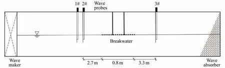
Fig.2 Sketch of the experimental horizontal perforated plate in the wave flume.

Fig.3 Sketch of the arrangement of holes on the horizontal plate.

Table 1 Experimental conditions for the model tests
In the model tests, the free surface elevationsηwere recorded by three capacitive-type wave gauges (Nos. 1 – 3)with a sampling frequency of 50 Hz. Typical time series of free surface elevations are presented in Fig.5. Wave gauge Nos. 1 and 2 were placed in front of the horizontal perforated plate, and wave gauge No. 2 was fixed 2.7 m away from the front of the plate. As the incident wave period changed, the position of wave gauge No. 1 was adjusted so that the distance between wave gauge Nos. 1 and 2 is consistently equal toL/4. The incident and reflectedHcould be obtained by decomposing the stableηbetweenT1andT2, which are respectively recorded by wave gauge Nos. 1 and 2, as shown in Fig.5(a), according to the method of Goda and Suzuki (1976). Wave gauge No. 3 was established 3.3 m away from the end of the plate.The transmittedHcould be calculated from the stableηbetweenT3andT4recorded by wave gauge No. 3viathe zero-up-cross analysis method. Thereafter,CRandCTwere determined. Each case in the experiment was repeated at least three times, and the experimental data revealed good repeatability. The average values ofCRandCTwere recorded as the final result.

Fig.4 Photograph of the horizontal perforated plate in the wave flume.

Fig.5 Time series of free surface elevations η recorded by wave gauge Nos. 1, 2, and 3 for the horizontal perforated plate (ε= 0.089, H/L = 0.01, T = 1.2 s).
4 Validation of the Analytical Solution
4.1 Convergence Examination of the Analytical Solution
Establishing the convergence of the analytical solution with an increasing number of iterative stepsMis necessary. Table 2 lists the calculation results of the unknown complex expansion coefficientsR0,A0,C0, andT0at differentM. The truncated numberNis set to 25, and the calculation conditions areb/h =2.0,δ/h= 0.003,ε =0.1,H/L =0.01,k0h= 2.0,θ= 15˚, andμ =2.3. Here, the valueμ= 2.3is only adopted to verify the correctness of the analytical solution. In fact,μmust be calibrated by using the test results. Table 2 shows that the calculation results converge rapidly and reach an accuracy of 10-4after 13 iterative steps. Moreover, the iterative calculations for all calculation cases considered in this study generally converge within 20 iterative steps.
The convergence of the series solution in terms of hydrodynamic parameters with increasingNis checked in Table 3.Table 3 shows the calculatedCRandCTwith increasingN. The calculation conditions areb/h =1.0,δ/h=0.003,ε =0.1,H/L =0.01,θ= 30˚,μ =2.3, and different values ofk0h. The square-root singularity of the fluid velocity at the edge of the plate is not considered in the analytical solution, which leads to the slow convergence of the calculated results (Porter and Evans, 1995; Evans and Peter,2011). Some authors have suggested setting the value ofNto 40 for engineering analysis, and this suggestion is adopted in the following calculations.
4.2 Comparison of the Analytical and Boundary Element Method Solutions
The analytical model proposed in this paper may also be solved by an independently developed iterative BEM(Liu and Li, 2017). A comparison of the iterative BEM results and the present analytical solutions for some typical hydrodynamic parameters is shown in Fig.6. The calculation conditions are identical to those listed in Table 3.Fig.6(a)shows that the agreement ofCTandCRobtained between the analytical and iterative BEM solutions are good. TheCFVvalues obtained between these solutions,which are shown in Fig.6(b), are excellent. Good agreement between the results of these two different solutions generally validates the correctness of the present iterative analytical solution.

Table 2 Convergence of the calculated expansion coefficients with increasing number of iterative steps M

Table 3 Convergence of CR and CT with increasing truncated number N

Fig.6 Comparison of the present analytical and iterative BEM solutions for a submerged horizontal perforated plate. b/h= 1.0, δ/h = 0.003, ε = 0.1, H/L = 0.01, θ = 30˚, μ = 2.3, and different values of k0h.
4.3 Comparison of the Analytical Solution and Experimental Data
Because the quadratic pressure drop condition is adopted in the analytical solution, providing the appropriateμandCis of great significance to achieve reasonable predictions of the hydrodynamic parameters.Cis determined by Eq.(6)in the present study. Molin (2011)provided a reference value ofμfor submerged horizontal plates withεless than 0.5, but this value is not necessarily applicable to the case of perforated plates at the still water level. Therefore,μin the iterative analytical solution is calibrated according to the present experimental results; the specific calibration method used is described by Heet al. (2021). Reasonableμvalues forεof 0.089 and 0.149 are 2.6 and 1.1, respectively, and excellent agreement between the calculation and experimental results is obtained. Wave breaking can be observed above the perforated plate in the case of incident waves withH/L= 0.02 and a relatively long period in the physical model test. However, the breaking of waves is not violent and its influence on wave energy dissipation may be assumed to be limited. Fig.7 reveals that theCRandCTcalculated by the analytical solution agree reasonably well with the experimental results. Therefore, theμvalues recommended in this experiment are also used in the following calculations and discussion.

Fig.7 Comparison of the analytical solutions and experimental results of a horizontal perforated plate at the still water level.
5 Calculation Results and Discussi on
The analytical solution was carefully examined using the experimental data under the attack of normally incident waves. Given the rationality of the analytical solution, the influence of different relative plate widthsb/h,θ, andH/Lon typical hydrodynamic characteristics of the horizontal perforated plate at the still water level is further investigated using calculation examples as follows.
Figs.8 and 9 respectively show the variations inCR,CT,CE, andCFVof the horizontal perforated plate with differentεof 0.089 and 0.149 under the combined effects of differentb/handk0h. The two figures illustrate thatCTis usually less than 0.5 whenb/h> 1.0 andk0h> 2.0, which means this cost-effective structure has very good sheltering functions for short waves. While for the long wave,the shelter effect is not ideal. Increasingb/hcan increaseCEandCR, which leads to a reduction inCT. However, the wave force increases slowly with increasingb/h, which is beneficial for the security and stability of perforated plates located at the still water level.
Figs.10 and 11 respectively show the variations inCR,CT,CE, andCFVof the horizontal perforated plate with differentεof 0.089 and 0.149 under the combined effects ofθandk0h. The horizontal perforated plate withε=0.089 has a largerCRcompared with the plate withε=0.149. Asθincreases, the wave component incident to the horizontal perforated plate decreases, which directly leads to decreases in wave force and wave energy dissipation,but theCRof the horizontal perforated plate increases.
Fig.12 shows variations in theCR,CT, andCEof the horizontal perforated plate withk0hfor differentH/L.Increases inH/Llead to general increases inCRandCEand a decrease inCTfor the horizontal perforated plate.These findings reveal that the sheltering function of the horizontal perforated plate improves with increasingH/L.However, the wave force exerted by long and steep waves on the horizontal perforated plate is relatively strong and may affect its functions.
6 Conclusions
In the present study, wave scattering by a horizontal perforated plate fixed at the still water level is investigated analytically and experimentally. The analytical solution adopts the quadratic pressure drop condition on the horizontal perforated plate at the still water level to consider the effect ofHon the wave energy dissipation directly. Velocity potential decomposition technology and a suitable iterative algorithm are then utilized to obtain the analytical solution. Moreover, the necessary physical model tests are conducted to validate the rationality of the proposed analytical solution. Convergence analysis shows that the iterative procedure and series solution present good convergence. The agreement between the present analytical solution and the independently developed iterative BEM solution is satisfactory. Reasonable values ofμare calibrated according to physical model tests for use in the corresponding calculation cases in the analytical solution.

Fig.8 Combined effects of k0h and b/h on CR, CT, CE, and CFV at ε = 0.089, H/L = 0.01, δ/h = 0.006, and θ = 0˚.
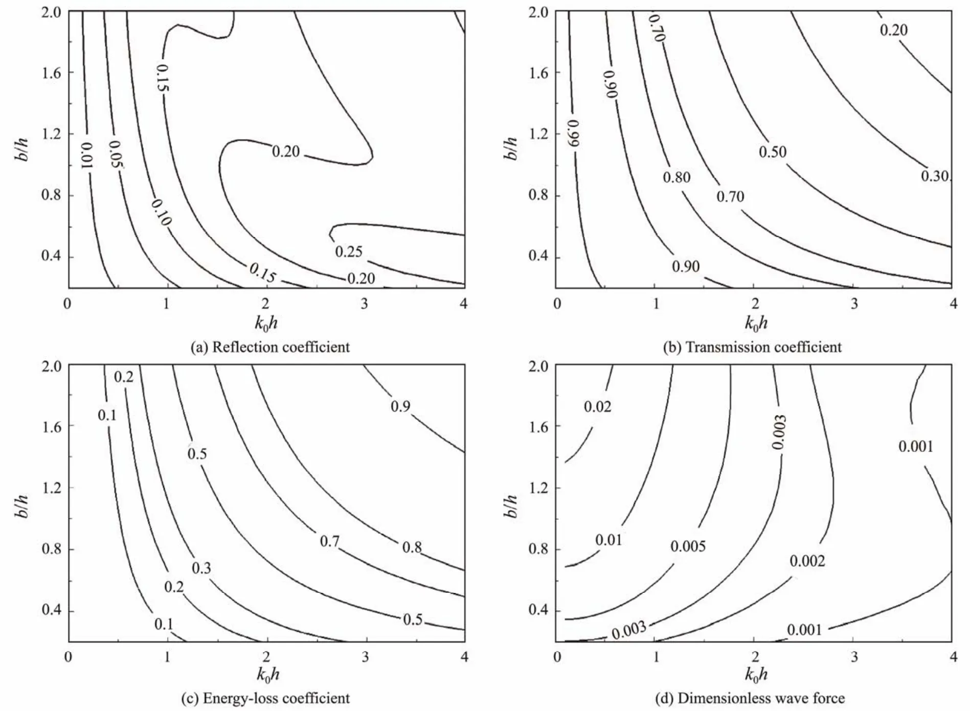
Fig.9 Combined effects of k0h and b/h on CR, CT, CE, and CFV at ε = 0.149, H/L = 0.01, δ/h = 0.006, and θ = 0˚.

Fig.10 Combined effects of k0h and θ on CR, CT, CE, and CFV at b/h = 1.56, ε = 0.089, H/L = 0.01, and δ/h = 0.006.

Fig.11 Combined effects of k0h and θ on CR, CT, CE, and CFV at b/h = 1.56, ε = 0.149, H/L = 0.01, and δ/h = 0.006.

Fig.12 Effects of wave steepness on CR, CT, CE, and CFV at b/h = 1.56, δ/h = 0.006, ε = 0.149, and θ = 0˚.
Given the rationality of typical calculation cases, the hydrodynamic performance of the horizontal perforated plate fixed at the still water level is carefully evaluated using the analytical solution. A horizontal perforated plate fixed at the still water level can offer a good sheltering effect for rear waters. Increasingb/happears to be an effective means to reduce theCTof long waves and only lead to little increase the wave forces imposed on the perforated plate.The good wave dissipation characteristics and mechanical properties of a horizontal perforated plate fixed at the still water level demonstrate its promising and useful applications in practical engineering. Heave horizontal perforated plates, which can well adapt to changes in sea water level(Fuet al., 2021), may be studied further in future research.
Acknowledgements
This study was supported by the National Natural Science Foundation of China (Nos. 51725903 and 52001293),and the Taishan Scholar Program of Shandong Province(No. ts20190915).
Appendix
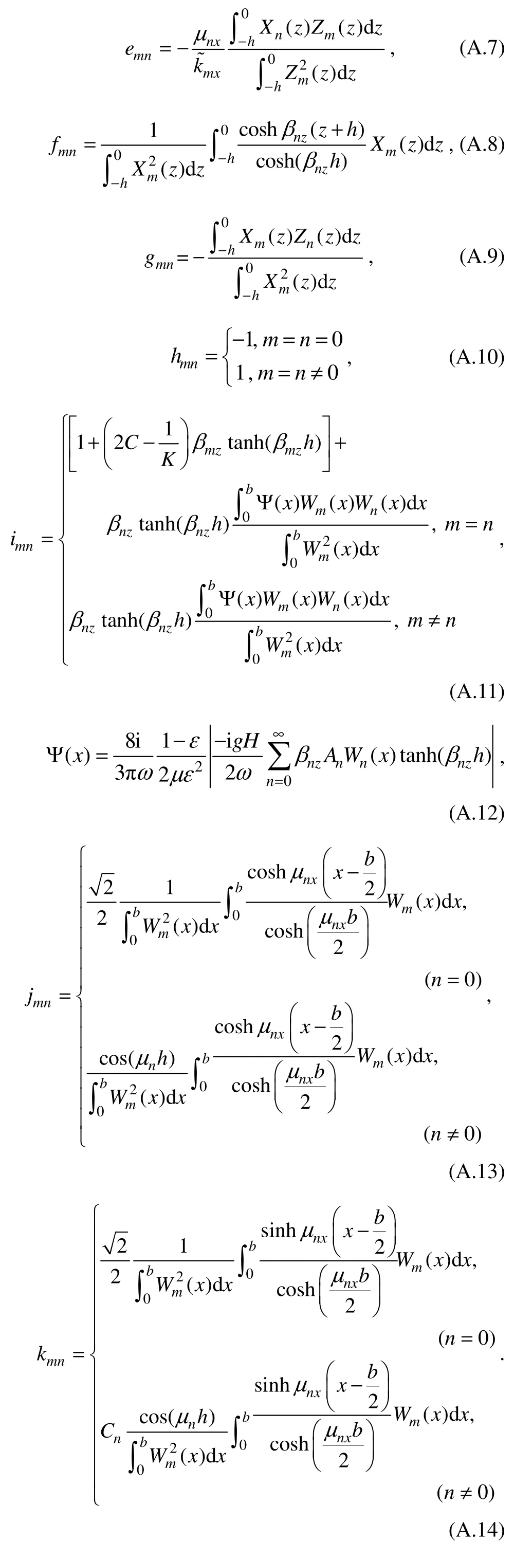
Matrix coefficients in Eqs. (39)– (43):

杂志排行

Journal of Ocean University of China的其它文章
- A Theoretical Model for the Microwave Emissivity of Rough Sea Surfaces
- Mechanism of Regional Subseasonal Precipitation in the Strongest and Weakest East Asian Summer Monsoon Subseasonal Variation Years
- Theoretical Prediction of the Bending Stiffness of Reinforced Thermoplastic Pipes Using a Homogenization Method
- Penetration Resistance of Composite Bucket Foundation with Eccentric Load for Offshore Wind Turbines
- Application of Converted Displacement for Modal Parameter Identification of Offshore Wind Turbines with High-Pile Foundation
- Time Domain Full Waveform Inversion Based on Gradient Preconditioning with an Angle-Dependent Weighting Factor