碱性电解液中K3[Fe(CN)6]在锌阳极上的自发还原和吸附延长锌镍电池的循环寿命
2022-11-24沈沅灏王擎宇刘杰钟澄胡文彬
沈沅灏,王擎宇,刘杰,钟澄,2,*,胡文彬,2
1天津大学材料科学与工程学院,先进陶瓷与加工技术教育部重点实验室,天津复合材料与功能材料化重点实验室,天津 300072
2天津大学-新加坡国立大学福州联合学院,天津大学国际校区,福州 350207
1 Introduction
Due to the growing demand for energy in modern society,fossil fuel is unable to support the development of human society in the future1. Hence, it is essential to enhance the efficient utilization of renewable energy. In this case, cheap, reliable, and eco-friendly grid-scale energy storage system plays a key role in optimizing energy structure2–6. Although high-performance lithium-ion batteries are currently the most popular batteries,inflammability and limited resource still restrict their application in grid-scale energy storage7,8. Besides, considering the toxicity and weak performance of the lead-acid battery, aqueous Znbased batteries have captured widespread attention because of their unique advantages9–13. Excellent safety, environmental benignity, and low toxicity make aqueous Zn-based batteries competitive in large-scale energy storage system. Among various Zn-based batteries, with high open-circuit voltage and rate performance, Zn-Ni battery has great potential in practical applications14. However, although Zn-Ni battery has a history of more than 100 years, the intrinsic obstacles of Zn anode in alkaline electrolyte, such as dendrite, shape change, passivation,and corrosion, still prevent their implementation from commercialization15,16.
To tackle the abovementioned challenges of Zn anode, many strategies have been applied, such as the introduction of additives, coating of active material, surface modification, and gel electrolyte17. Among these strategies, by virtue of excellent uniformity and feasibility, electrolyte additives have gathered tremendous interest and showed great potential in the practical application of Zn-Ni batteries18–22. According to composition,electrolyte additives can be divided into organics and inorganics.For inorganic additives, metallic compounds with high hydrogen evolution overpotential dissolved in the electrolyte, such as Bi2O3and In2O3, can be reduced and deposited as Bi and In on the anode during charging, which can inhibit the corrosion and enhance the conductivity of anode18–20. Some inorganic salts(e.g., KF and K2CO3) can reduce the solubility ofin alkaline electrolyte21,22. Moreover, Ca(OH)2can makebecome insoluble calcium zincate, and avoid the occurrence ofin the electrolyte23. With regard to organic additives,they are often used to inhibit dendrite and self-corrosion of Zn anode in alkaline electrolyte. For instance, vanillin has been used to suppress dendrite in alkaline electrolyte24. And the synergism of imidazole (IMZ) and polyethylene glycol (PEG) can inhibit the corrosion of Zn anode25. Besides, some additives (e.g.,polyethylenimine, cetyltrimethylammonium bromide, and sodium dodecyl sulfate) can adsorb on the anode, which can inhibit both dendrite and self-corrosion26,27. On the contrary,some studies also introduced ethanol and dimethyl sulfoxide as additives to improve the solubility of Zn species in the electrolyte, which can inhibit the passivation of Zn anode28,29.As viewed from the abovementioned studies, the directions of modification and functions of additives are quite different, which is induced by the lack of systematic study on the failure reason of Zn-based batteries.
With regard to the primary failure reason of Zn-based batteries, many different opinions have been proposed in previous studies due to the differences in test conditions and battery systems30–33. To get a better insight of the failure reason of practical Zn-Ni battery, a systematic study was carried out by our group24. Based on the results of characterization and simulation, the failure reason of practical Zn-Ni battery is the shape change induced by Zn dissolution and uneven current distribution, which points out the direction for subsequent modification. In addition, corrosion of the Zn anode will accelerate capacity loss and passivation as well26,35.Accordingly, we focus our modification on inhibiting the corrosion and dissolution of Zn species.
According to previous literature, K3[Fe(CN)6] can inhibit the corrosion of Zn metal in KOH solution26. Moreover, because of the strong binding of Fe3+and Fe2+with CN–, [Fe(CN)6]3−and[Fe(CN)6]4−are relatively stable in alkaline solution and have been used as redox pairs in alkaline redox-flow battery for many times37–39. In this study, K3[Fe(CN)6] is introduced to Zn-Ni battery as electrolyte additive to inhibit the shape change of Zn anode.
2 Experimental
2.1 Preparation of the electrolyte
The pristine electrolyte used in Zn-Ni battery is ZnO-saturated 30% (mass fraction) KOH solution with LiOH additive. Besides,different mass fractions (0.25%, 0.5%, and 1%) of K3[Fe(CN)6]are introduced as electrolyte additive. After the addition of K3[Fe(CN)6], the electrolyte changes from colorless transparent to yellow transparent, which is the modified electrolyte. When there is no special emphasis, the mass fraction of K3[Fe(CN)6]in the modified electrolyte is 0.5%.
2.2 Fabrication of Zn-Ni full battery
The electrodes are manufactured according to the formula proposed by our group. The anode consists of ZnO, Zn, Al2O3,Bi2O3, polyvinyl alcohol, potassium polyacrylate,poly(tetrafluoroethylene) (PTFE), and Cu mesh (current collector). The cathode consists of CoOOH-coated Ni(OH)2, Zn,CoO, carboxymethyl cellulose, PTFE, and Ni foam (current collector). The functions of various components have been provided in detail in the previous study9,34. The abovementioned materials are provided by Hunan Yuanda New Materials Co.,Ltd. With regard to the pouch battery, to be closer to the situation of lean electrolyte in practical application, the mass ratio of electrodes and electrolyte is limited to ~3 : 1. And the specific assembly method is consistent with our previous study34.
2.3 Characterization techniques
Electrochemical Impedance Spectroscopy (EIS) of the fabricated batteries was obtained using an electrochemical workstation (CHI 660E, Shanghai Chenhua), with an initial potential of 1.2 V and a frequency range of 0.1 Hz to 1 × 10⁵Hz.The surface morphology of the Zn plates and Zn anodes are investigated using optical microscopy (OM, VXH-2000C) and scanning electron microscopy (SEM, Hitachi S7800). The X-ray photo-electron spectroscopy (XPS, Axis Supra, Britain) test is applied to investigate the chemical composition. Besides, the phase of the reaction product and Zn anode is confirmed with X-ray diffraction (XRD, Bruker D8 Advanced). The composition of the reaction product between Zn and K3[Fe(CN)6] is measured by ICP-OES (Aglient 7800). To understand the difference in wettability between the two electrolytes, the dynamic contact angles on the Zn plate are tested on optical contact angle system(Dataphysics DCAT21).
2.4 Electrochemical measurements
Electrochemical impedance spectroscopy (EIS) and Tafel polarization curve are conducted on electrochemical workstation(CHI 660E, China) with three-electrode system, in which Zn plate, Pt plate, and Hg/HgO electrode are used as work electrode,counter electrode, and reference electrode, respectively. For EIS tests, the frequency range is 10 mHz to 100 kHz. Besides, the scanning range and scanning rate of Tafel tests were ±0.3 V (vs.open circuit potential) and 5 mV·s−1, respectively.
For Zn-Ni full battery, all electrochemical tests are performed on the JINFAN battery test system (JFBTS, China). In the longterm cycle test, Zn-Ni batteries are measured at a 5 A discharge current with 50% depth of discharge (1.25 Ah). The batteries are charged with 2.5 A to 1.9 V and then with a constant voltage (1.9 V) to a certain capacity (1.275 Ah, charge an extra 2% to counteract side reactions). To acquire actual initial capacity, the batteries are discharged at 5 A to 1.2 V. Moreover, Zn-Ni batteries are also charged/discharged between 1.2 and 1.9 V to measure capacity retention and rate performance.
3 Results and discussion
To get a further insight of the effect of K3[Fe(CN)6] on Zn corrosion, Zn plates were soaked in the pristine electrolyte and modified electrolyte, respectively. As shown in Fig. 1a, Zn plates in the pristine electrolyte did not change significantly after immersion, while the surface of Zn plates in the modified electrolyte began to darken. Moreover, the modified electrolyte also changed from yellow transparent solution to colorless transparent solution. Obviously, K3[Fe(CN)6] was chemisorbed on the Zn plates and formed a dark surface. First, the surface morphology of soaked Zn plates was observed by SEM. As viewed in Fig. S1 (Supporting Information), the surface of pristine Zn plate is completely smooth with only a few scratches.After soaking in the pristine electrolyte for 1 day, the surface of Zn plate becomes uneven and a few holes appear. By comparison, no difference in morphology can be observed on the Zn plate soaked in the modified electrolyte. The morphology of the Zn plates soaked in the two electrolytes is almost the same at high magnification, while the Zn plates soaked in the modified electrolyte show more holes at low magnification. For this phenomenon, we speculate that it is relevant to the reaction between Zn and K3[Fe(CN)6]. And further experiments were carried out to explore the reaction mechanism and products between Zn and K3[Fe(CN)6].
To explore the composition of the surface layer, XPS test was carried out on the soaked Zn plate after the residual electrolyte was completely washed (Fig. 1b–f). According to the survey spectra, compared with the Zn plate soaked in the pristine electrolyte, the signals of Fe and N were detected on the Zn plate soaked in the modified electrolyte. This result proved that Zn reacted with K3[Fe(CN)6] and formed trace amounts of new substance on the surface of Zn plate. Because SEM images and EDS did not detect any special morphology and elements, it can be inferred that the reaction product of chemisorption is only several atomic layers thick on the surface of Zn plate. To confirm the chemical component of the reaction product, the highresolution spectra of each element were analyzed.
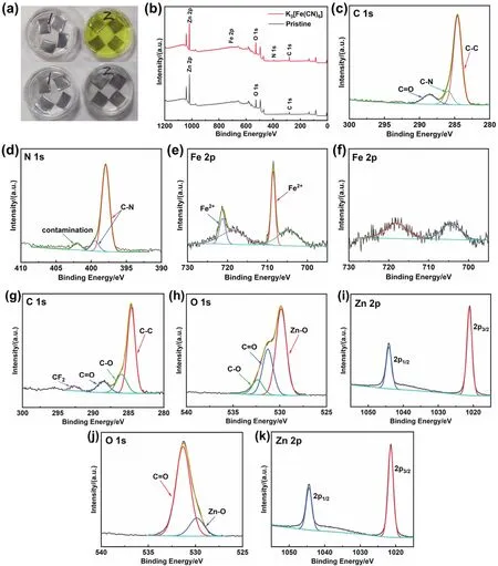
Fig. 1 Immersion test of Zn plates in the pristine electrolyte (marked as 1 in Fig. 1a) and modified electrolyte (marked as 2 in Fig. 1a). (a) The initial stage of immersion (top), and after immersing for 1 day (bottom). XPS spectra of the Zn plates after immersing in the electrolyte with and without K3[Fe(CN)6]: (b) comparison of survey spectra, (c) C 1s, (d) N 1s, and (e) Fe 2p high-resolution spectra of the Zn plate soaked in the modified electrolyte. (f) high-resolution spectrum of Zn plate soaked in the pristine electrolyte in the Fe 2p region. (g–i) High-resolution spectra of C, O, and Zn elements for Zn plate soaked in pristine electrolyte. (j–k) High-resolution spectrum of O and Zn elements for Zn plate soaked in modified electrolyte.
First, the existence of C-N can be determined by the highresolution spectra of C 1s and N 1s40–42. The N 1s peaks at 397.9 and 399.3 eV demonstate that N exists in the cyanide ligand40,41.However, the Fe 2p signals are not entirely consistent with the conventional peak position of Fe 2p. As shown in Fig. 1e, there are four peaks in Fe 2p spectrum, located at 704.8, 708.6, 718.6,and 721.3 eV respectively. But the peaks at 704.8 and 718.6 eV can’t be well assigned to Fe 2p. According to the survey spectra,the spectrum of Zn plate soaked in the pristine electrolyte also appears slight fluctuation in this region. Therefore, through comparative analysis with literature, this pair of peaks with lower binding energy may be the interference brought by other elements43. As viewed from Fig. 1f, a pair of peaks also appeared in the Fe 2p spectrum of the Zn plate soaked in the pristine electrolyte, whose position and shape are similar to that of the Zn plate soaked in the modified electrolyte. It indicates that the pair of peaks at 704.8 and 718.6 eV in Fig. 1e don’t belong to Fe element. After removing the interference, according to the fitting results of Fe 2p in Fig. 1e, the Fe 2p peaks situated at 708.6 and 721.3 eV can be ascribed to Fe 2p1/2and Fe 2p3/2of K4[Fe(CN)6]41,44. However, the high-resolution spectrum of C 1s doesn’t show the signal of K element near 292 eV45,46.Therefore, there is no K element on the Zn plate, and the ferrocyanate interacts with Zn or forms a chemical bond.Besides, for comparison, the XPS spectra of O 1s and Zn 2p and all the corresponding XPS spectra for Zn soaked in the pristine electrolyte are provided in Fig. 1g–k.
Although XPS spectra provide a great deal of information for determining reaction products, due to the low content of target products and elements, XPS test results can’t fully confirm product information. One possibility is that some of soluble products will be lost during the washing process of Zn plates.Therefore, Zn powder and modified electrolyte were used for magnification experiments. The Zn powder was poured into the modified electrolyte. And it was found that the color of the yellow transparent solution quickly lightened. After a short agitation, the solution became milky white suspension. Finally,the tiny white floccule precipitated to the bottom. The solution is almost colorless and transparent, indicating that the product is difficult to dissolve in the electrolyte. To analyze the product composition, after the Zn powder precipitated, the upper suspension was immediately poured into the centrifugal tube to centrifuge the floccule. As the floccule was soluble in water, the unwashed product was tested by XRD directly after drying. Fig.2a shows the XRD patterns of the centrifuged product. After comparison with the PDF standard card, the main components are K4[Fe(CN)6] (PDF#32-0801) and K2CO3(H2O)1.5(PDF#73-0470). Since the product is directly dried without washing, the residual KOH will be carbonated to K2CO3(H2O)1.5when it is dried in the air. It can be determined that Zn powder will reduce Fe3+in K3[Fe(CN)6] to Fe2+, and finally produce K4[Fe(CN)6]that is insoluble in alkaline electrolyte. In addition, the XRD patterns show that the diffraction peaks at 24.68° and 28.46° are stronger than those of standard PDF cards, which correspond to(250) and (260) crystal planes of K4[Fe(CN)6] lattice,respectively. The results show that K4[Fe(CN)6] grows preferentially on the two crystal planes. The structure of K4[Fe(CN)6] changes and finally precipitates as white floccule instead of light yellow transparent crystal (a common crystal form of K4[Fe(CN)6]).
However, there are some differences between this product and XPS results. The characteristic peak of K element is not detected in the XPS spectrum, indicating that ferrocyanate doesn’t combine with K ion. Therefore, the Zn powder after reaction with K3[Fe(CN)6] was washed and measured by ICP-OES to confirm the composition of the reaction product on the Zn powder. As viewed in Fig. 2b, the results show that the mass ratio of Fe and K in the solution obtained by dissolving the Zn powder is 1.42. According to K4[Fe(CN)6] chemical formula, the theoretical mass ratio of Fe and K should be 0.36, much lower than the actual value. Hence, the reaction product on the surface of Zn powder is not only K4[Fe(CN)6] but also Zn2[Fe(CN)6] or other ferrocyanide. The experimental results show that the Zn powder will continue to reduce the remaining K3[Fe(CN)6] after forming a ferrocyanide layer on the surface. Nevertheless,because the outer reduction products can not directly contact Zn,K4[Fe(CN)6] will be formed and attached to the surface. The reaction mechanism and process are similar to a previous literature on the reduction of graphene oxide by Zn metal47. The reduction products on the surface won’t prevent the Zn from reducing the outer substances.
The dynamic contact angle test in Fig. 2c and Fig. S2 reveals the effect of K3[Fe(CN)6] additive on the wettable properties of Zn plate. At the initial stage of contact, the contact angle between the modified electrolyte and Zn plate is almost the same as that of the pristine electrolyte, indicating that their wettability for Zn plate is very close. However, as time goes on, the contact angle between the modified electrolyte and Zn plate is gradually larger than that of the pristine electrolyte, which indicates that the wetting speed slows down. Combined with XPS and XRD results, it can be speculated that this is because the Zn gradually reacts with K3[Fe(CN)6] in alkaline electrolyte, forming a protective layer which can inhibit the contact between the electrolyte and Zn plate.

Fig. 2 (a) XRD patterns of white floccule in the modified electrolyte after the reaction. (b) The mass ratio of Fe and K of Zn powder after reaction measured by ICP-OES. (c) Dynamic contact angle test of the pristine electrolyte and the modified electrolyte on the surface of Zn plates.
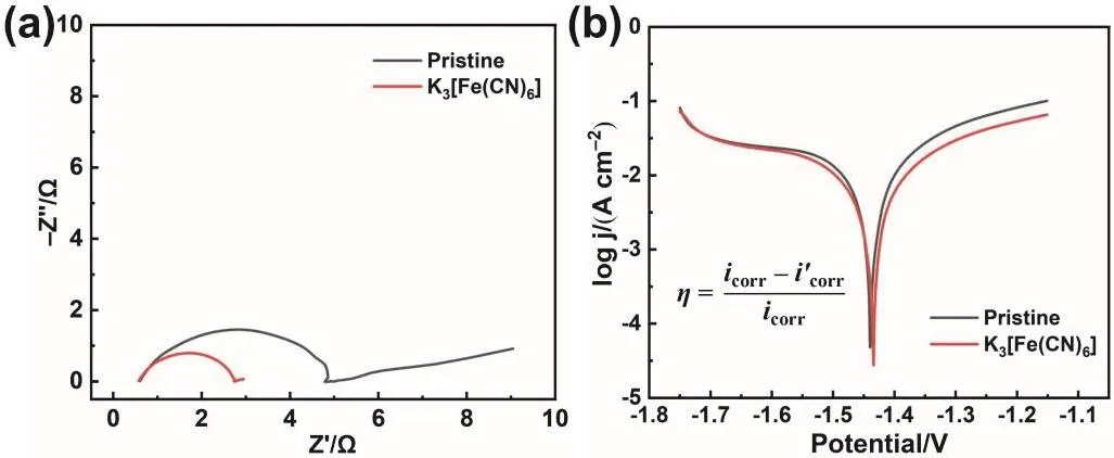
Fig. 3 Electrochemical performance test of the pristine electrolyte and modified electrolyte. (a) EIS curves, (b) Tafel polarization curves.
To further explore the effect of K3[Fe(CN)6] additive, the electrochemical performance of the modified electrolyte was tested in simplified three-electrode system. In Fig. 3a, the EIS curve displays a typical Nyquist plot that consists of a semicircle in high-frequency region and a diffusion line in low-frequency region. The semicircle is ascribed to charge transfer resistance(Rct), whose radius reflects the magnitude of Rct. Hence,K3[Fe(CN)6] additive significantly reduces the Rctcompared with the pristine electrolyte. Besides, EIS test is also conducted to measure the ionic conductivity. As shown in Fig. S3, the intercept between the EIS curve and Z’ axis is the internal resistance of the electrolyte. Hence, the internal resistances of the two electrolytes are similar, indicating similar ionic conductivity. Unlike conventional organic additives, as a salt with complex ion, K3[Fe(CN)6] not only doesn’t delay the kinetics of the reaction but promotes the reaction. Then, the influence of the modified electrolyte on Zn anode corrosion was studied by Tafel polarization curve test (Fig. 3b). The results show that compared with the pristine electrolyte system, the modified electrolyte has little influence on the corrosion potential of Zn anode, but reduces the corrosion current48,49.Based on the calculation of the formula shown in Fig. 3b, the addition of K3[Fe(CN)6] makes the inhibition efficiency reach 41.15%. According to the electrochemical tests, K3[Fe(CN)6] is expected to be an electrolyte additive that can simultaneously inhibit the dissolution of Zn species without affecting the electrochemical reaction rate. According to the experimental phenomenon and characterization results, the chemical composition of protective layer is ferrocyanide. And the most likely product is K4[Fe(CN)6]. The possible chemical equation is as follows:

In general, the reduction of Rctindicates that Zn plate is more likely to react in this solution and has good reaction kinetics.Therefore, in theory, the corrosion rate of Zn plate should increase as well, which is not consistent with the results of Tafel test. By observing the Zn plates after test, it is found that the surface of the Zn plate tested in the pristine electrolyte is relatively dark, while the surface of the Zn plate tested in the modified electrolyte has many bright spots. Given this characteristic, the surface of Zn plate was further observed by optical microscope. As viewed in Fig. 4a, b, the surface of the Zn plate tested in the pristine electrolyte is severely corroded,with few areas of metallic luster remaining visible. However, the surface of the Zn plate tested in the modified electrolyte (Fig. 4c,d) still has many square areas with metallic luster, indicating that the corrosion of these areas is much weaker. Combined with the above mechanism investigation, the characteristic morphology is likely to be caused by the reaction product between the Zn surface and K3[Fe(CN)6]. In the Tafel polarization curve test,lower electrode potential may promote the reduction of K3[Fe(CN)6] on the Zn plate, and form a protective layer of ferrocyanide in part of the region with high activity, which inhibits the subsequent corrosion. To further study the surface morphology and composition, Zn plates were observed by SEM.As viewed from Fig. S4 and S5, the surface of the Zn plate tested in the modified electrolyte also shows many relatively flat square areas, in which only Zn element can be detected. This result shows that corrosion in these square areas is indeed inhibited.
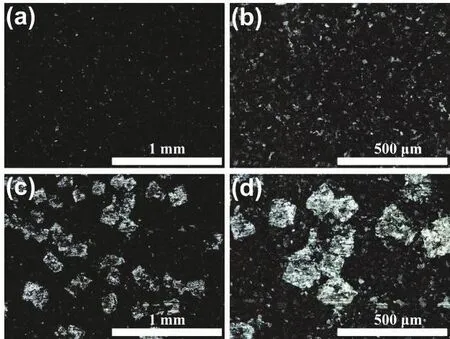
Fig. 4 Optical morphology of Zn plates after Tafel polarization curve test at different magnifications. (a, b) Zn plate tested in the pristine electrolyte, (c, d) Zn plate tested in the modified electrolyte.
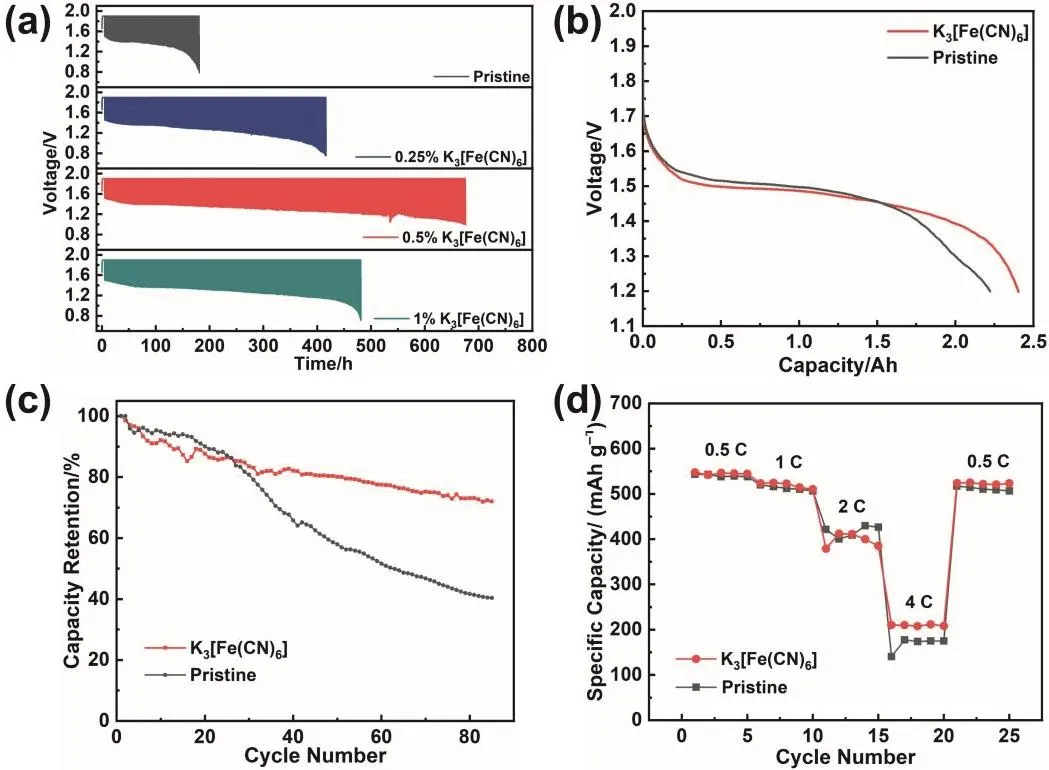
Fig. 5 Electrochemical performance of Zn-Ni batteries using the pristine electrolyte and the electrolyte with different mass fractions of K3[Fe(CN)6].(a) Cycling performance of the batteries discharged at 5 A, (b) discharge curve of the batteries discharged at 5 A,(c) capacity retention of the batteries discharged at 5 A, and (d) rate performance of the batteries.
In addition to the electrochemical test based on the threeelectrode system, Zn-Ni full battery was assembled to further test the effect of K3[Fe(CN)6] additive on the performance of the battery. Fig. 5a shows the cycling performance of the batteries in the pristine electrolyte and the electrolyte with different mass fractions K3[Fe(CN)6]. The cut-off voltage of the Zn-Ni battery with pristine electrolyte is reduced to below 0.8 V after 124 cycles. The addition of K3[Fe(CN)6] significantly improves the cycling performance of Zn-Ni batteries. Before the cut-off voltage is lower than 0.8 V, the Zn-Ni battery with 0.25% K3[Fe(CN)6] cycled 269 times, and the Zn-Ni battery with 1% K3[Fe(CN)6] cycled 340 times. Surprisingly, after 423 cycles, the cut-off voltage of Zn-Ni battery with 0.5% K3[Fe(CN)6] is still above 1 V. Compared with the Zn-Ni battery with pristine electrolyte, the cycling life of the battery with 0.5% K3[Fe(CN)6]is improved by more than three times. Fig. 5b exhibits the discharge curves of Zn-Ni batteries in the pristine electrolyte and modified electrolyte when the discharge current is 5 A. At the initial stage of discharge, the voltage platform of the modified battery is slightly lower compared with the pristine battery.However, its discharge platform declines more slowly, and more capacity can be released eventually. According to subsequent characterization, because the anode cycling in the pristine electrolyte is loose, it is easier to contact the electrolyte at the beginning of discharge, which leads to a higher initial discharge platform. But as the discharge goes on, some Zn is surrounded by ZnO and unable to discharge (called “dead” Zn), which reduces the effective capacity and voltage of the battery. In the modified electrolyte, due to the compact structure, the anode discharges layer by layer without “dead” Zn. In this case, the battery with modified electrolyte exhibits a more stable discharge platform and releases more capacity. From the perspective of capacity retention (Fig. 5c), the battery with pristine electrolyte exhibits only 40% capacity retention after 85 cycles, while the battery with modified electrolyte shows 72% capacity retention. Moreover, the corresponding coulombic efficiency curve is provided in Fig. S6. According to the rate performance test of the battery (Fig. 5d), considering that the electrode is thick, the electrolyte is more difficult to enter the electrode and the diffusion polarization is larger. Therefore, the capacity is significantly reduced when discharging at high rate.At low rate, the specific capacities of Zn anode cycling in the pristine electrolyte and modified electrolyte are similar.However, at a high rate, the battery with modified electrolyte can release more capacity, indicating that the modified electrolyte reduces the battery polarization, and is more conducive to quick discharge. In addition, the GCD (galvanostatic chargedischarge) curves of Zn-Ni batteries using pristine and modified electrolyte under different cycle numbers and current densities are provided in Fig. 6.
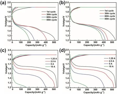
Fig. 6 The GCD curves of Zn-Ni batteries using pristine (Fig. 6a, c) and modified (Fig. 6b, d) electrolyte under(a, b) different cycle numbers and (c, d) current densities.
To reveal the actual mechanism of K3[Fe(CN)6] additive in Zn-Ni battery, the Zn anode after the cycling was further analyzed. Fig. 7a shows an optical image of the anode after 125 cycles in the pristine and modified electrolyte. The Zn anode cycling in the modified electrolyte (on the right of Fig. 7a) is white, and there is no dark segregation layer. As viewed from Fig. 7b, XRD pattern of the anode cycling in modified electrolyte shows only the peaks of ZnO, but almost no peaks of Zn and Bi, which means there is no Zn and Bi near the surface.This result proves that the anode cycling in the modified electrolyte is free of “dead” Zn and segregation of additive.
Moreover, we observed the morphology of Zn anode and conducted EDS analysis by SEM (Fig. 7c–h). The characteristic morphology of Zn anode surface is mainly divided into dark surface layer and white active material (Fig. 7c). The EDS results of the two characteristic areas indicate that the white region of the anode cycling in the pristine electrolyte contains only Zn and O elements, while the dark area also contains C, F, Bi, and Al elements. Consistent with the results in our previous study, in the pristine electrolyte, the electrode additive and binder of the Zn anode are segregated on the surface to form a dark surface layer,and the white active material is ZnO34. As for the anode cyclingin the modified electrolyte (Fig. 7f–h), its surface is almost white region. And the SEM image shows that the region is formed by ZnO spiny ball. EDS results also reveal that there are no other elements except Zn and O on the surface of this region. Hence,for the anode cycling in the modified electrolyte, there is no additive and binder segregation on the surface.
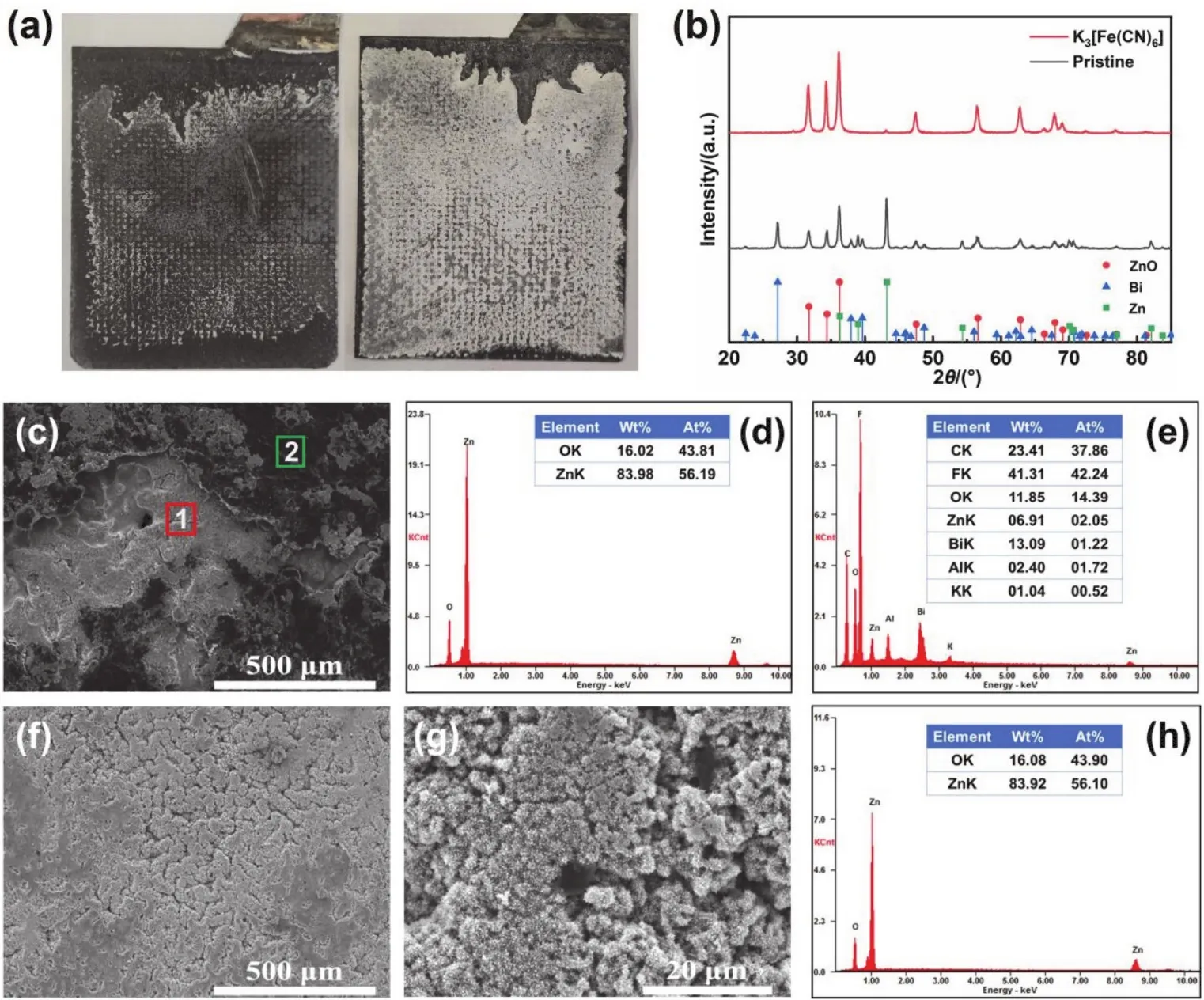
Fig. 7 (a) Optical images of the anodes after 125 cycles in the pristine/modified electrolyte, and (b) XRD patterns of the anode after 125 cycles in the pristine/modified electrolyte. SEM images and EDS results of the anode after 125 cycles in the pristine/modified electrolyte.(c) Morphology of the anode cycling in the pristine electrolyte, (d) EDS results of white region 1 in Fig. 7c, (e) EDS results of dark region 2 in Fig. 7c, (f, g) morphology of Zn anode cycling in the modified electrolyte at different magnifications, and (h) the EDS result of Fig. 7f.
Fig. 8 shows the cross-sectional images of Zn anode after 125 cycles in the pristine electrolyte and modified electrolyte,respectively. The anode in discharge state was first observed. As for the anode cycling in the pristine electrolyte (Fig. 8a–c), it has an uneven surface, relatively loose structure, and obvious shape change. Besides, a large amount of Zn metal (area with metallic luster) is surrounded by ZnO (gray area). Considering that the electron transport is limited, it can’t discharge and becomes“dead” Zn. In contrast, for the anode cycling in the modified electrolyte (Fig. 8d–f), the following two significant characteristics can be found: (1) the anode has a flat surface and relatively compact structure, without obvious shape change; (2)the discharge process of the anode is carried out layer by layer from outside to inside, which can be reflected by the clear interface between ZnO and Zn. The outer area of the anode has been completely transformed to gray ZnO, without “dead” Zn isolated by ZnO in Fig. 8a–c. To obtain more information about the mechanism of K3[Fe(CN)6], the cross section of the anode in charge state after 125 cycles is also analyzed. As viewed from Fig. 8g–i, for the anode cycling in the pristine electrolyte, due to serious shape change, the thickness of each region varies significantly. In addition, the Zn tends to aggregate and form larger Zn blocks or grains. This is unfavorable to ion transport when the outer layer of the Zn grain has discharged and turned into ZnO, which may be one of the reasons for “dead” Zn.However, for the anode cycling in the modified electrolyte (Fig.8j–l), it is obvious that most of the internal Zn is uniformly distributed in small particles. And there is no aggregation of Zn,which is in favor of ionic diffusion to the inner layer of Zn particles. According to previous literature, K4[Fe(CN)6] is often introduced into table salt as an anti-caking agent, which can effectively inhibit the aggregation and dissolution of NaCl at high humidity50–52. Therefore, the reasons for the uniform distribution of Zn particles in the anode can be speculated as follows: In the modified electrolyte, the growth of Zn particles in the anode is accompanied by the continuous accumulation of K4[Fe(CN)6] on its surface. The formation of K4[Fe(CN)6] layer not only prevents the contact among Zn particles, but also slows down the transport of Zn(OH)42−, which ultimately inhibits the aggregation growth of Zn. Moreover, it can also be observed from the cross section that the thickness of Zn anode cycling in the modified electrolyte is relatively uniform, without obvious shape change.
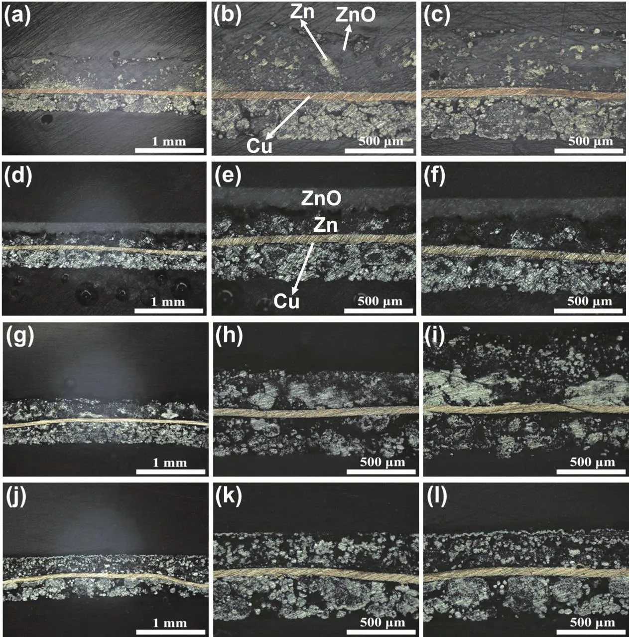
Fig. 8 Optical cross-sectional images of different positions in the central region of the anode after 125 cycles (reaction side is facing up). Discharged Zn anode in (a–c) pristine electrolyte, and (d–f) modified electrolyte. Charged Zn anode in (g–i) pristine electrolyte, and (j–l) modified electrolyte.
The XPS survey spectrum of Zn anode after 125 cycles (Fig.9a) shows that the anode in the pristine electrolyte can detect obvious signals of F and Bi elements. However, except for Zn,O, and C, no signals of other elements are detected on the anode cycling in the modified electrolyte. As viewed from the fitting results of the C 1s spectra (Fig. 9b, c), the peak at 292.2 eV is significantly higher than other peaks, which can be assigned to CF2of the binder in the anode53,54. These results indicate that the surface is composed of active materials (Zn and ZnO) rather than the segregation of binder and electrode additive. For Fig.9d, except for the interference peak brought by Zn, no signal of Fe can be detected. Combined with XRD results, the reduction product of K3[Fe(CN)6] is likely to exist as K4[Fe(CN)6] in the battery, which is insoluble in the electrolyte but soluble in water during washing process
According to the above exploration, the mechanism of K3[Fe(CN)6] additive in Zn-Ni battery can be simplified as Fig.10. The dark background area is the mixture of active material in charge state, binder, and additive. And the light gray background area is the mixture of active material in the discharge state, binder, and additive. For the anode cycling in the pristine electrolyte, the Zn tends to aggregate and form larger blocks or grains, which is hard to entirely react during discharge. Besides,electrode additives and binder of the anode (e.g., Bi2O3and PTFE) segregate at the surface, which affects the uniform distribution of components and the performance of anode. For the anode cycling in the modified electrolyte, XPS test can roughly confirm that the K3[Fe(CN)6] exists and acts in the form of K4[Fe(CN)6] during the cycling. And there is no other insoluble ferrocyanide. However, according to the ICP test,K4[Fe(CN)6] is only slightly soluble in the pristine electrolyte(~0.2 g·L−1). Therefore, K4[Fe(CN)6] is likely to exist as flocculent precipitation and tiny amounts of [Fe(CN)6]4–after reduction on Zn anode. K4[Fe(CN)6] attached to the surface of Zn can effectively improve the affinity between Zn and other electrode additives, so that Zn anode does not occur segregation,and maintains uniform distribution. The uniform distribution of the electrode binder is beneficial to maintaining a compact structure of Zn anode, which makes the anode structure less susceptible to damage. And the uniform distribution of Bi2O3not only improves the conductivity of the anode but also makes the conductivity of each region relatively uniform. It is beneficial to decrease the resistance and balance the current distribution of Zn anode. K4[Fe(CN)6] attached to the surface of Zn can also regulate the transfer of Zn(OH)42−, and inhibit the continuous aggregation of Zn, which keeps Zn particles relatively uniform and small. Moreover, K4[Fe(CN)6] can inhibit the contact between the electrolyte and Zn anode, reducing the corrosion and dissolution. During the discharging process, because the structure of the anode cycling in the modified electrolyte is uniform, OH–is transmitted layer by layer. And it is difficult for the inner active material to preferentially obtain OH−for reaction. Therefore, the anode cycling in the modified electrolyte shows the characteristic of layer-by-layer discharge without“dead” Zn. And the utilization rate of the active material has been greatly improved.
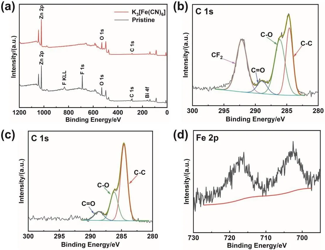
Fig. 9 XPS spectra of the anodes cycling in the pristine electrolyte and the modified electrolyte. (a) Comparison of survey spectra,(b) the C 1s high-resolution XPS spectrum of the anode cycling in the pristine electrolyte, and (c, d) high-resolution XPS spectra of the anode cycling in the modified electrolyte in the (c) C 1s and (d) Fe 2p region.
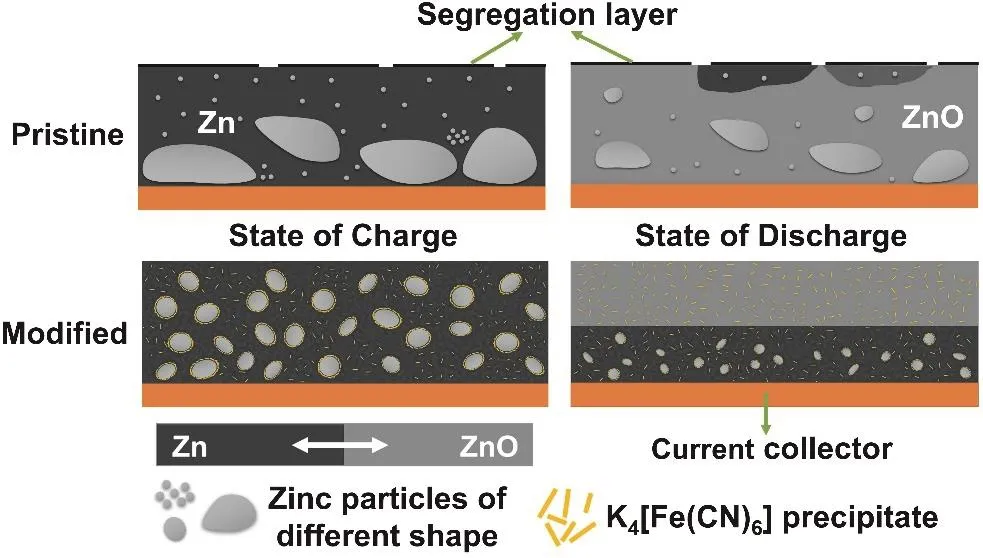
Fig. 10 Mechanism diagram of K3[Fe(CN)6] electrolyte additive in Zn-Ni battery.
4 Conclusions
In this study, to overcome the shape change of Zn anode,K3[Fe(CN)6] is applied as electrolyte additive of Zn-Ni batteries.Furthermore, through rational experimental design and characterization, the reaction mechanism of Zn and K3[Fe(CN)6]is explored. According to XRD and XPS tests, we reveal that Zn metal can react with K3[Fe(CN)6] in aqueous KOH solution, and reduce [Fe(CN)6]3–to [Fe(CN)6]4–. The Zn-Ni batteries with K3[Fe(CN)6] additive exhibit a much longer cycling life, which can realize a cycling life three times longer than the battery without K3[Fe(CN)6]. Under the same number of cycles, Zn anode cycling in the modified electrolyte not only shows smaller shape change but also no “dead” Zn and segregation of electrode additives and binder. Besides, unlike conventional organic additives which increase the electrode polarization, K3[Fe(CN)6]can also improve the discharge capacity and rate performance of Zn-Ni batteries. Hence, by virtue of excellent feasibility and low cost, as an electrolyte additive with almost no negative effect,K3[Fe(CN)6] shows tremendous potential in promoting the commercialization of Zn-Ni batteries.
Supporting Information:available free of charge via the internet at http://www.whxb.pku.edu.cn.
