Electrical and aerodynamic characteristics of sliding discharge based on a microsecond pulsed plasma supply
2022-11-17TaifeiZHAO赵太飞QianZHANG张倩BoruiZHENG郑博睿YuanpengLIU刘园鹏YuanzhongJIN金元中andQuanlongCHEN陈全龙
Taifei ZHAO(赵太飞),Qian ZHANG(张倩),Borui ZHENG(郑博睿),Yuanpeng LIU(刘园鹏),Yuanzhong JIN(金元中) and Quanlong CHEN(陈全龙)
1 School of Automation and Information Engineering,Xi’an University of Technology,Xi’an 710048,People’s Republic of China
2 The Green Aerotechnics Research Institute of Chongqing Jiaotong University,Chongqing 401120,People’s Republic of China
Abstract Plasma flow control technology has broad prospects for application.Compared with conventional dielectric barrier discharge plasma actuators(DBD-PA),the sliding discharge plasma actuator(SD-PA)has the advantages of a large discharge area and a deflectable induced jet.To achieve the basic performance requirements of light weight,low cost,and high reliability required for UAV(Unmanned Aerial Vehicle)plasma flight experiments,this work designed a microsecond pulse plasma supply that can be used for sliding discharge plasma actuators.In this study,the topology of the primary circuit of the microsecond pulse supply is determined,the waveform of the output terminal of the microsecond pulse plasma supply is detected using the Simulink simulation platform,and the design of the actuation voltage,the pulse frequency modulation function and the construction of the hardware circuit are achieved.Using electrical diagnosis and flow field analysis,the actuation characteristics and flow characteristics of sliding discharge plasma under microsecond pulse actuation are studied,the optimal electrical actuation parameters and flow field characteristics are described.
Keywords:plasma flow control,microsecond pulse plasma supply,sliding discharge plasma
1.Introduction
Plasma flow control is a new type of active flow control technology based on plasma pneumatic actuation,which has the advantages of fast response times,wide frequency bandwidths,and no moving parts.In 2005,plasma flow control was listed as one of the six basic research topics led by science and technology in the United States.In the same year,China listed plasma dynamics and magnetic fluids as one of the major strategic needs in the national aviation field[1,2].The two key points of plasma flow control are the plasma actuator and the plasma supply.In 1994,Rothet alfirst proposed that the surface dielectric barrier discharge under atmospheric pressure has a good flow control effect[3].In subsequent studies,more and more scholars improved the flow control performance by proposing different structures of plasma actuators.In 2009,Subrataet alproposed a horseshoe-shaped plasmonic actuator and demonstrated the capability of this configuration in flow control[4].In 2020,Rodrigues and Páscoa proposed combining the micro-exposed electrodes with stair-shaped dielectric layers.It is shown that using this combination,it is possible to achieve mechanical efficiencies eight times greater than in a conventional macro-actuator.At the same time,degradation tests demonstrated that stair-shaped dielectric layers degraded slower and led to an increased lifetime[5].Since the asymmetric arrangement of the electrodes leads to the coupling of momentum into the surrounding air,in 2013,Erfaniet alused multiple-packaged electrodes to generate higher velocities based on the conventional dielectric barrier discharge plasma actuator[6].In 2012,Songet alstudied the characterization of a three-electrode sliding discharge plasma actuator actuated by a nanosecond negative DC actuation.It was found that negative DC voltage increased the plasma discharge intensity and particle density[7].Different configurations have different flow control capabilities,and this work will study the performance of the three-electrode sliding discharge plasma actuator.
Another key point of plasma flow control is the plasma supply,which is also an important part of generating atmospheric low-temperature plasma.Research on plasma supply can primarily be divided into millisecond plasma supplies,microsecond plasma supplies,and nanosecond plasma supplies.In 2012,Gibalovet alstudied the discharge characteristics of plasma actuated by a millisecond plasma supply and found that the plasma control effect of millisecond plasma supply was weak.At higher actuate frequencies,the plasma supply body heats up markedly,which also affects the performance of the plasma actuator[8].In 2018,the experimental results of Wei showed that millisecond plasma supply can achieve a steady control effect under low-speed flow conditions,but the plasma discharge is unstable,which is likely to cause breakdown or creepage of the actuator[9].The millisecond plasma supply primarily drives the charged particles in the plasma to move directionally.The charged particles collide with the gas molecules in the air to generate body force in the flow field and accelerate the near-wall jet at the same time.However,most millisecond plasma supplies consume a lot of energy and cannot maintain high space charge density and high electric field during discharge;the resulting control is typically lost with high-speed flows.
To improve the control efficiency of plasma supplies,researchers have tried to perform plasma flow control experiments using a nanosecond pulse plasma supply that can generate instantaneous fast pulse actuation.Unlike millisecond plasma supplies,nanosecond pulse plasma supplies concentrate all discharge energy in a one-nanosecond pulse,and the instantaneous discharge energy is large in the flow field,causing rapid changes in air density and pressure and generating a shock effect.In 2014,Zhaoet alused a nanosecond pulse plasma supply to actuate the plasma,to study the shockwave generated by a single discharge under different pulse voltages.After the first pulse,a series of damped oscillations would appear,because of the internal instability of the nanosecond pulse plasma supply,due to nanosecond pulse energy dissipation[10].In 2019,Xieet alshowed that the nanosecond pulse plasma supply provides good control at a high inflow velocity(0.8 Ma)but it can cause strong electromagnetic interference(EMI)during experimentation that can seriously interfere with airborne equipment.This makes it difficult to use in engineering applications[11].
To solve the problems of weak flow control in millisecond plasma supplies and strong electromagnetic interference in nanosecond plasma supplies,researchers have turned to study microsecond pulsed plasma supplies,which combine the advantages of millisecond plasma supply and nanosecond plasma supply to generate induced jet and shockwave at the same time.Although the velocity of the induced jet is marginally lower than that of the millisecond plasma supply,the propagation speed of the shockwave is near that of the nanosecond plasma supply.The compound control effect has better flow control efficiency and has been successfully applied to UAV flight control[12,13].At the same time,the energy consumption of the microsecond pulse plasma supply is lower than that of the millisecond plasma supply,and the electromagnetic interference is weaker,which is more suitable for engineering applications.
Based on the comprehensive analysis above,this work is based on the practical application of plasma flight experiment.With consideration for the performance,body and cost of the plasma supply,a microsecond pulse plasma supply that actuates the plasma through periodic high-voltage pulses is developed.In this study,the performance of the plasma supply is verified,and the electrical and aerodynamic characteristics of the sliding discharge plasma under the actuation of microsecond pulses are analyzed and described.
2.Basic principles of microsecond pulsed plasma supply
The microsecond pulse plasma supply is primarily composed of five modules:AC input,rectification filtering,resonant charging,signal control,and high voltage output.Its primary circuit topology is shown in figure 1.
Because sinusoidal alternating current changes smoothly and does not generate higher harmonics easily,it can protect the insulation performance of the electrical equipment and reduce energy consumption while the electrical equipment is operating.Therefore,a 0-250 V adjustable alternating current is connected to the microsecond pulsed plasma supply as the input.The rectifier filter module filters the negative half cycle signal of the input sinusoidal AC signal through a singlephase rectifier bridge and outputs a pulsating DC signal.The filter capacitor C1is connected in parallel with the output end of the rectifier bridge to reduce the AC ripple coefficient and smooth the DC output voltage waveform.To make the DC voltage waveform as smooth as possible,the ripple coefficient of the output voltage of the rectifier filter circuit is best controlled below 5%.The filter capacitor value is calculated by equation(1):
In equation(1),because the filter capacitor charges quickly,it is negligible compared to the discharge time through the load;thus,Δtis set toT/2=10 ms,whereRis the load resistance,andKris the ripple coefficient.
For optimal filtering,the discharge speed of the capacitor must be slow enough.The slower the capacitor discharges,the smoother the output voltage and the better the filtering effect.Equation(2)expresses the relationship between the capacitor discharge time constant and the capacitor capacity and load:
In equation(2),Kτis the capacitor discharge time constant,Ris the load resistance andCis the capacitor.
Then calculating the available filter capacitorμ=C624 F,to ensure the capacitor has sufficient capacity,the filter capacitor value chosen is 1000 μF.Due to the large capacitance of aluminum electrolytic capacitors and their great ability to store charge,this type of capacitor is selected for filter capacitors.At the same time,a portable capacitor discharge circuit is set up for the filter capacitor,to prevent the residual charge in the capacitor from causing unsafe accidents after the experiment.
After rectification filtering,the capacitor is charged through the resonant circuit,and the charging voltage of the capacitor increases exponentially.When the charging starts,the instantaneous current is large.Therefore,a current limiting resistor is connected to limit the charging speed of the capacitor.As the capacitor voltage increases,the charging current decreases gradually.
The signal control circuit inputs the drive signal to the IGBT driver board through the signal generator,and then the IGBT driver board controls the turning on and off of the IGBT switching device.Because the gas discharge can effectively increase the peak discharge supply in a short time scale,it produces a strong pulse disturbance[14],so it is necessary to select an IGBT with short turn-on and turn-off times.After comprehensive consideration,the model selected is MG400V1US51A.
Since the IGBT has a high repetitive peak reverse current in this experiment,an IGBT protection circuit is added.The fast recovery diode D6is used to limit the voltage on the resistor R1,so that R1is bypassed during the charging process,which can not only prevent the device from being damaged due to any excessive collector voltage of the IGBT,but also reduce the charging loss of R2.The capacitor C3absorbs the energy of the signal control part.When the IGBT is turned off,the collector current will flow to the capacitor C3to charge,suppress the peak voltage and current when the IGBT is turned on and off,and reduce the switching loss.The value of capacitor C3is calculated by:
In equation(3),Icis the maximum collector current,tris the maximum rise time of the collector current,tfis the maximum fall time of the collector current,andVceis the voltage between the collector and the emitter of the IGBT.
Finally,the low-voltage input is converted into a highvoltage output by a transformer.A high-pressure silicon stack is used to filter out the negative half-cycle pulse wave,and the output peak is a 0-20 kV adjustable high-voltage pulse.
3.Simulation analysis
The Simulink software is chosen for circuit simulation,to verify the correctness of the main circuit topology design and parameter selection,and further optimize the circuit parameters.The filter capacitor parameter is set to 1000 μF,and the signal generator provides a square wave signal to the IGBT driver board.The peak voltage of the square wave signal is 20 V and the frequency is 1 kHz.The simulation diagram of the microsecond pulse plasma supply software is shown in figure 2.The‘Powergui’module is the simulation configuration module of the power system,which can display the current and voltage of the circuit system in the steady state and all the state variable values of the circuit(inductor current and capacitor voltage).It needs to be initialized during the simulation process.The simulation waveform in this work is viewed through the oscilloscope.
The output waveform of the microsecond pulse plasma supply is displayed by the scope oscilloscope in the Simulink simulation model.The simulation waveform is shown in figure 3.Considering the running speed of the software,the simulation time is set to 1 s.By observing the output waveform of the oscilloscope,the microsecond pulse period can be obtained.It is determined by the frequency of the square wave signal provided by the signal generator.If the square wave signal is 1 kHz,the microsecond pulse period is 1000 μs.The arrow indicates the amplified waveform of a single pulse.It can be observed that the width of a single pulse is 2 μs.Software simulation results show that the circuit topology can fulfill the experimental requirements.In the next section,the electrical characteristics and aerodynamic characteristics of the microsecond pulse plasma supply will be verified experimentally.
4.Electrical characteristics of the microsecond pulsed plasma supply
A three-electrode sliding discharge plasma actuator was used in this experiment,as shown in figure 4(a).the left image is the top structure and the right image is the bottom structure.The actuator consists of two exposed electrodes and one covered electrode.The two exposed electrodes are made of copper foil(thickness=0.02 mm),and the distance between the two exposed electrodes along the surface of the actuator is 20 mm;the insulating dielectric layer is made of three layers of Kapton,each with a thickness of 0.192 mm and the total thickness is 0.576 mm,the widths of the exposed electrodes and the covered electrodes are 2 and 20 mm respectively,and the lengths are both 150 mm.
When the actuator is working normally,the exposed electrode 1 is connected to the high-voltage output terminal of the microsecond pulse supply,the exposed electrode 2 is connected to the negative electrode of the DC supply,and the negative electrode of the microsecond pulse plasma supply and the positive electrode of the DC supply are grounded together with the covering electrode.The negative DC high voltage applied by the exposed electrode 2 is provided by a dual-channel high-voltage DC power supply(CX-300B).The input voltage is AC(180-250 V),the output current is 0-10 mA,and the output voltage DC1 of channel 1(plasma discharge distance between positive and negative electrodes is less than 4 cm)is 5-30 kV.The output voltage DC2 of channel 2(the plasma discharge distance between the positive and negative electrodes is less than 2 cm)is 2.5-15 kV.Considering the configuration parameters of the plasma actuator,the output voltage DC2 of channel 2 is selected as the input voltage of the plasma actuator in this experiment.
We connected the voltage probe(Tektronix P6015A)and the current probe(Tektronix TCP0030A)to the high voltage output of the microsecond pulse plasma supply,and used the voltage probe and the current probe to measure the plasma actuation voltage and actuation current,and displayed these through the oscilloscope(ADS1102CAL)to see parameters such as the output voltage waveform and pulse frequency.In this experiment,we only tested the discharge voltage and current of the microsecond pulsed plasma supply,and did not detect the DC power supply voltage and current.In future research,we will detect the voltage and current of the DC power supply.
Through repeated electrical measurements,it is concluded thatVμs=7 kV is the initial voltage of the sliding discharge.WhenVμs=12 kV,the effect of the sliding discharge is relatively uniform.Therefore,the experimental parameters of the microsecond pulse plasma supply in this paper are set to 7 and 12 kV,and the pulse frequency is 1 kHz.As shown in figure 5,the left image(a)is the conventional DBD discharge image under the actuation of a microsecond pulse plasma supply,and the middle image(b)and the right image(c)are the sliding discharge effects of superimposed positive DC and negative DC,respectively.The microsecond pulse superimposed with DC has different discharge effects.
In this experiment,we assumed that the plasma discharge width was approximately equal to the glow discharge width.In the process of calculating the width of the plasma discharge,the first step is to establish the coordinate scale in the plasma discharge area,as shown in figure 5.We obtain the resolution of the plasma discharge image through the CCD camera(resolution=2871×944),and then calculate the total pixels of the discharge image.The correspondence between the total pixel points and the actual distance is established by using the coordinate ruler,and the plasma discharge width under different discharge conditions can be solved by solving the distance corresponding to a single pixel.
In equation(4),lsrepresents the actual distance corresponding to a single pixel;gtrepresents the actual total distance of the plasma discharge area,andxpixandypixare the horizontal and vertical pixels in the plasma discharge image,respectively.By equation(4),the DBD discharge width is calculated to be about 3 mm,and the superimposed positive DC is similar to the DBD discharge effect,but has more filamentary discharge channels and is larger than the DBD discharge.As shown in figure 5(b),the width of the plasma discharge was approximately 4 mm.However,after superimposing negative DC,a large-area sliding discharge effect will be produced.The discharge width can reach 20 mm,which is nearly filled the space between the two exposed electrodes.In a manner similar to[15,16],the expansion of the region primarily depends on the number and drift rate of positive ions generated in the positive half-cycle.
The negative DC component increases the number of positive particles and simultaneously accelerates the drift velocity of the positive ions,resulting in a stable and uniform surface discharge with a discharge area between the two electrodes,covering the exposed surface gap between the two electrodes[17].The local texture phenomenon in the upper discharge in figure 5(c)may be caused by some weak air gaps in the manual manufacturing process of the plasma actuator but does not affect its overall discharge characteristics.
The energy conversion in the plasma-induced air flow primarily includes four aspects:reactive supply loss between the supply and the actuator,supply loss in the heating of the actuator insulating layer,supply for maintaining the plasma,and the motion of the charged particles in the plasma required supply[18].In a discharge cycleT,the total input supplyPis determined by the discharge voltageUμsand the discharge currentIμs.
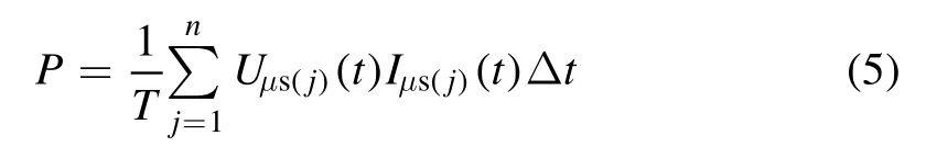
In equation(5),Tis the discharge cycle,jis the number of measurements,UμsandIμsare the output voltage and current of the microsecond power supply respectively,Δtis the time interval.
Corresponding to the voltage-current characteristics of the microsecond pulse sliding discharge in figure 6,the total input supply of the microsecond pulse plasma supply is calculated to be 28 W.Lianget alestimated that the power consumption of the millisecond power supply is about 63 W,which is 35 W less than that of the millisecond supply,indicating a marked reduction in the supply consumption[19].
Studies have shown that due to the steep rising edge of the nanosecond pulse,the discharge filaments are more concentrated along the edge of the electrode,and the instantaneous single pulse energy is large.When the nanosecond pulse width is 50 ns,the maximum temperature of the plasma actuator can reach 78°C.Some experiments predict that when the microsecond pulse width is 2 μs,the maximum temperature of the plasma actuator may be between 64°C and 68°C.In the future,we will increase the input energy of a single pulse by increasing the pulse frequency,and study the temperature and energy changes caused by pulse discharge[20].
5.Research on the aerodynamic characteristics of a microsecond pulsed plasma supply
The shock effect is one of the three physical effects of plasma flow control.The biggest difference between microsecond pulse actuation and others is that it can generate a shockwave and an induced jet at the same time.A microsecond pulse plasma supply can also produce both a conventional aerodynamic and a shock effect.This section combines two different experimental methods to qualitatively and quantitatively analyze the aerodynamic characteristics of microsecond pulsed plasma discharges.First,a schlieren system is used to capture the instantaneous structural morphology of the shockwave induced by the microsecond pulsed discharge,and time-averaged measurement of the velocity of the induced jet in the actuator surface area is performed by particle image velocimetry.
5.1.Shock effect
This section primarily investigates the shock effect of the sliding discharge plasma actuator under different DC voltages and obtains the relationship between the electrical parameters and the shockwave velocity.The schlieren system uses the multifunctional schlieren flow field display system produced by Yangzhou Luwei Industrial Technology Development,including the primary concave mirror,the light source integrated body,and the imaging system.The high-speed schlieren experimental layout is shown in figure 7.Inside the dotted line is the real picture of the microsecond pulse plasma supply.The diameter of the primary concave mirror is 150 mm,and the focal length is 750 mm.The light source integrated body is composed of an LED point light source,a light source base,and an adjustable aperture.The imaging system consists of the high-speed camera and the cutting blade.The high-speed camera is Phantom V2012,which has a maximum resolution of 1280×800,a maximum shooting speed of 651150 frames per second(standard),the minimum exposure time of 1 μs,and a memory of 72 GB.The resolution of this experiment is 512×384,and the exposure time is 1.5 s.
To compare the configuration of the shockwave generated by superimposing a microsecond pulse with different negative DC voltages,the high-speed camera frequency is set to 50 kHz.Table 1 shows the experimental conditions,and the schlieren experimental results are shown in figure 8,wheretis the shooting time interval.In figure 8,the black solid line isx=x1,(x1,0)is the position of the exposed electrode 1(microsecond supply),the black dotted line isx=x2,and(x2,0)is the position of the exposed electrode 2(DC supply).
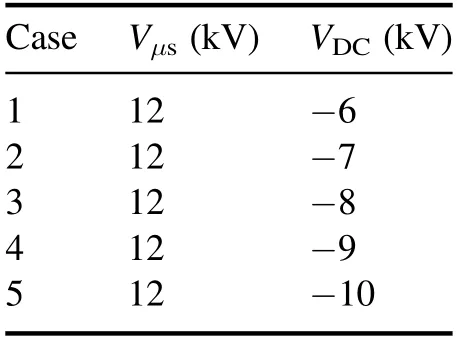
Table 1.Sliding discharge plasma actuation parameters.
To accurately measure the speed of the shockwave propagation,the scope of the viewing window is first calibrated in a static state.WhenVDC=-6 kV,the actuator begins to work,and when the actuator is turned on,a marginal disturbance of the flow field is observed.Bright spots are generated around the two exposed electrodes near the positions ofx=0 andy=0 in figure 8,which may be caused by electronic transitions generated by gas particles ionized,collided,and actuated under the action of an electric field.Whent=φ+20μs,because the high-voltage pulse discharge concentrates all the energy on a short time scale and releases it instantaneously,the pressure on the surface of the actuator increases suddenly,resulting in a local temperature rise and pressure rise,and the surface of the actuator expands rapidly to form a hemispherical shockwave.At this time,the speed of the shockwave is approximately 380 m s-1.
Whent=φ+40μs andt=φ+60μs,the range of the shockwave continues to expand and finally exceeds theviewing window due to its high speed.In this study,the effect of nanosecond pulse actuation is different.Nicolas and Takashima found that nanosecond pulse actuation can generate a shockwave centered at the electrode junction,the top is a strip structure,and the wave speed is maintained at approximately 343 m s-1[21,22].The experimental results of Roupassov also identified a strip structure formed by the superposition of multiple shockwave peaks[23].These experimental results agree with the shockwave morphology with nanosecond pulse actuation.In this experiment,the shockwave generated by the microsecond pulse discharge is hemispherical,and the calculated shockwave velocity is approximately 380 m s-1,which is marginally higher than that generated by the nanosecond pulse.These results may be caused by the fact that the negative DC voltage enhances the electric field strength of the entire actuator surface during the sliding discharge process.At the same time,as shown in figure 9,the speed of the shockwave also increases as the negative DC voltage continues to increase.By comparing the data after cubic fitting,the two lines were found to be nearly coincident,which proves that the propagation velocity of the shock wave has an approximately linear growth relationship with the negative DC voltage.
5.2.Airflow characteristics
This section primarily investigates the airflow characteristics of the sliding discharge plasma actuator under different DC voltages,determines the relationship between the electrical parameters and the velocity of the induced jet,and preliminarily describes the microsecond sliding discharge plasma flow control mechanism.The peak voltage of the microsecond pulse plasma supply was set to 12 kV,and the frequency was fixed to 1 kHz.The particle positions of the two laser pulses are recorded by particle image velocimetry,and 121 A/B frame images are continuously captured by a high-speed camera(the two laser pulses are defined as the A-frame laser and the B-frame laser respectively,and the delay time between the two lasers isΔt).According to the time delay between the two lasers and the displacement of the tracer particles,the 121 pieces of particle motion trajectory data were averaged,and the velocity vector of the induced jet was calculated using the cross-correlation algorithm.
The particle size of the tracer particles is an important factor affecting the followability of the particles.In this experiment,smoke(carbon particles)was selected as the tracer particles,and the particle diameter was about 2 μm.Since the DC electrode has strong adsorption to particles,the glass cover and the electrode will be ventilated and cleaned in each experiment to deal with the particles adsorbed on the exposed electrode.
Figure 10 shows the airflow characteristics of the sliding discharge plasma under the actuation of different DC voltages.In figure 10,①Vμs=12 kV,VDC=-7 kV;②Vμs=12 kV,VDC=-8 kV;③Vμs=12 kV,VDC=-9 kV;④Vμs=12 kV,VDC=-10 kV,x=0 and 20 mm are the positions of exposed electrode 1(microseconds supply)and exposed electrode 2(DC supply),respectively.When the actuator begins to work,the microsecond electrode generates a leftward jet.Due to the adsorption of the DC electrode,the direction of induced jet is curved from left to right in a circular arc to the direction of the DC electrode,and the direction of the velocity vector also points clockwise from the microsecond electrode to the DC electrode.Experimental results verify that the DC electrode can adsorb positive ions.Steven showed that the sliding discharge plasma induced directions to the right under AC superimposed negative DC actuation[24].The sliding discharge plasma under AC actuation has the opposite direction of the induced jet.At the same time,when the plasma actuator is working,an elliptical‘cavity’was formed between the exposed electrode 1(microsecond supply)and the exposed electrode 2(DC supply).This results in the inability of the tracer particles to enter the cavity,which may be due to charge deposition on the surface of the medium.Experimental results thus show that with a continuously increasing DC voltage,the cavity area gradually decreases and weakens into a slender strip.The specific cause and mechanism of this phenomenon must be investigated in more detail.
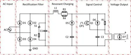
Figure 1.Primarily circuit topology of the microsecond pulse plasma supply.
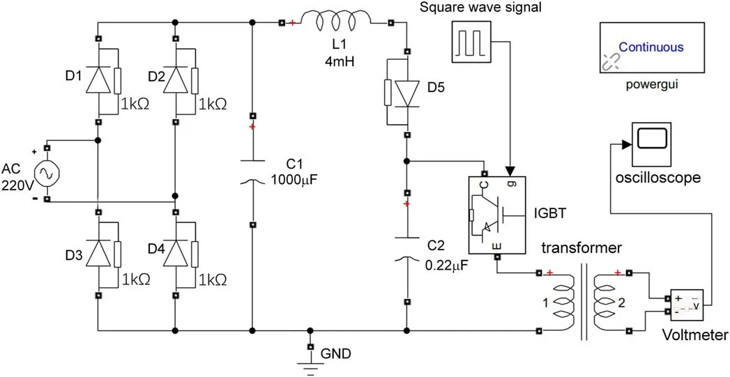
Figure 2.Simulink simulation diagram.
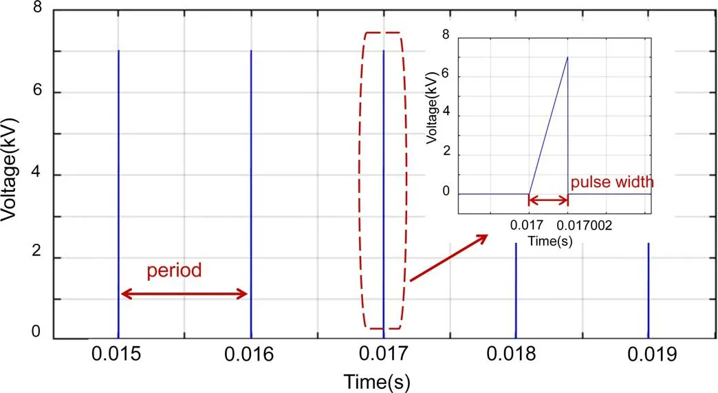
Figure 3.Simulink simulation output waveform.
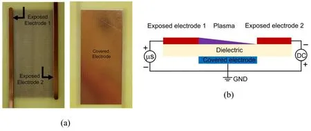
Figure 4.Sliding discharge plasma actuator.(a)Physical map,(b)schematic.
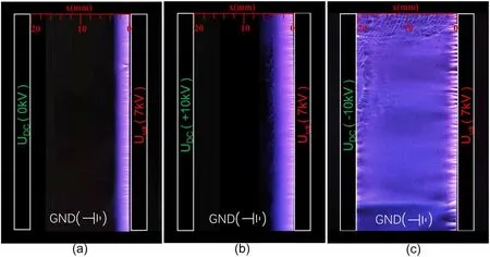
Figure 5.The microsecond pulse sliding discharge morphology under different DC voltages.
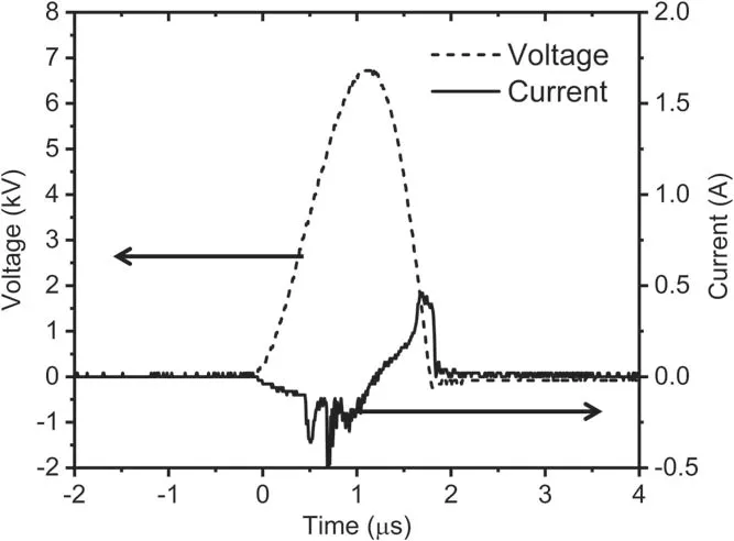
Figure 6.Voltage-current diagram of microsecond pulse sliding discharge actuation.
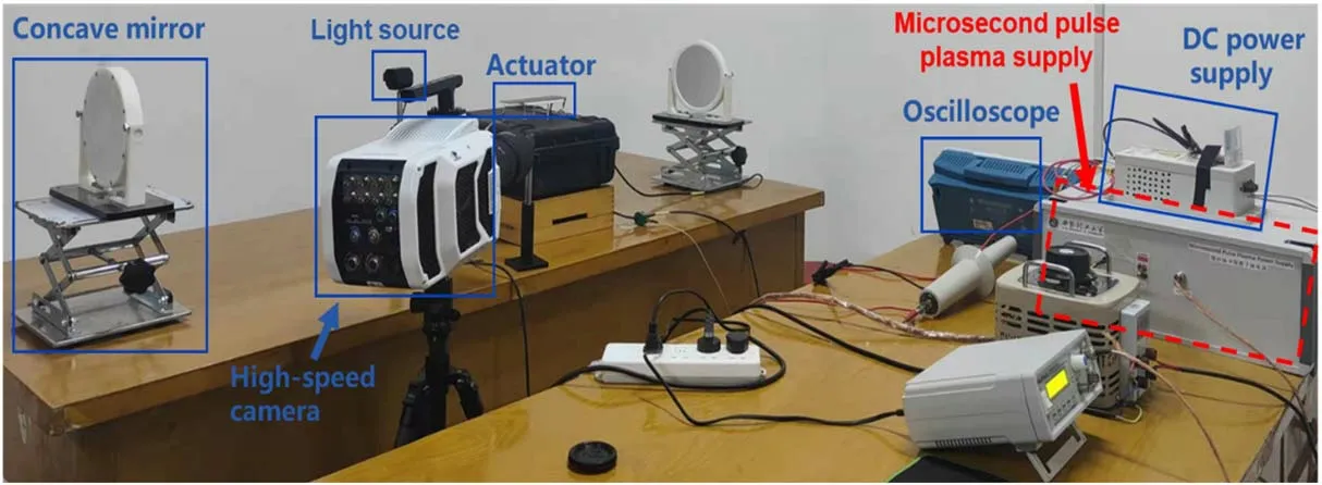
Figure 7.High-speed schlieren system.
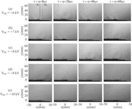
Figure 8.Compressible flow structure induced by pulsed sliding discharge plasma on the microsecond timescale.(From top to bottom,the DC voltage increases from-6 to-10 kV).
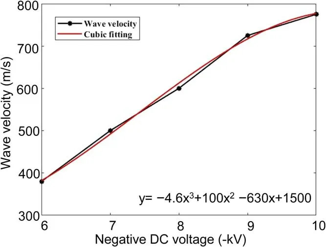
Figure 9.Relationship between shock wave velocity and negative DC voltage.
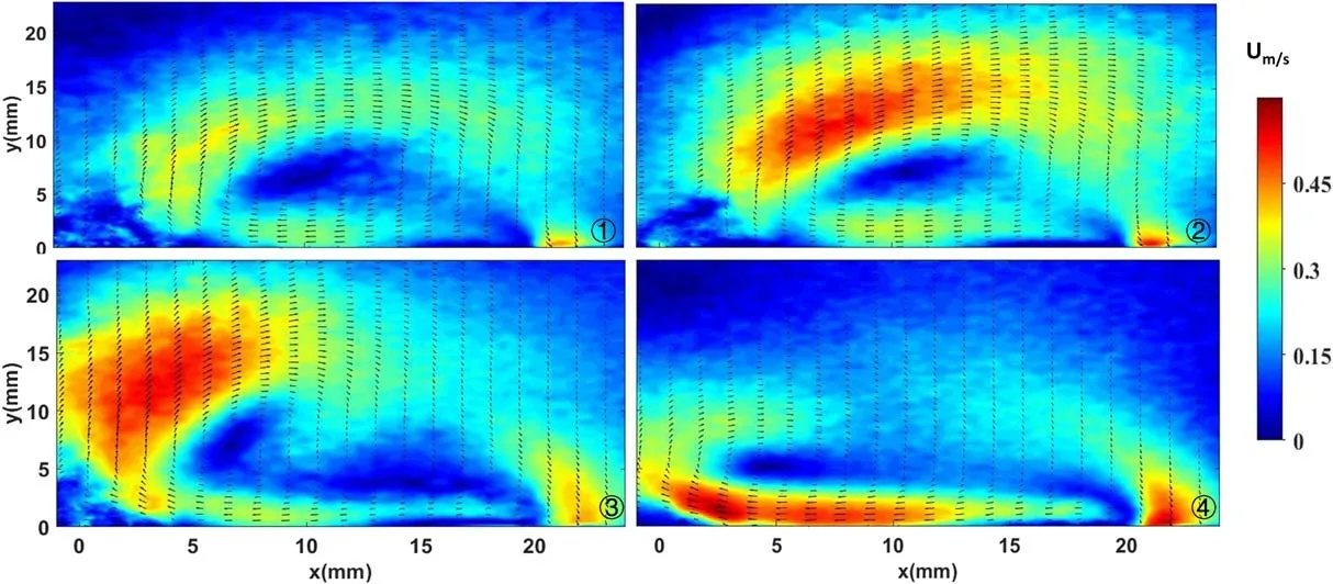
Figure 10.Jets induced by microsecond pulses under different DC voltages.
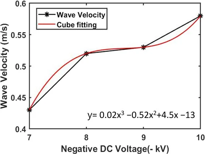
Figure 11.Relationship between jet velocity and negative DC voltage.
In this experiment,the velocity vector is calculated by the cross-correlation of the window in the A frame recorded at timet1and the same window in the B frame recorded at timet2.Assuming that the image function corresponding to a certain area in the flow field at timet1is:
then the image function corresponding to timet2is:

The cross-correlation function ofI1(x,y)andI2(x,y)is computed by:
According to the definition of the autocorrelation function,the autocorrelation functionr(fx,fy)of the functionI(x,y)is expressed as:

Therefore,equation(8)can be transformed into:r(f x,fy),combined with equation(10),equation(11)can be
Since the autocorrelation function satisfies≥()r0,0 obtained:
In summary,by calculating the cross-correlation function of the image function of a certain region in the flow field corresponding to two moments,and according to the location of the maximum value of the cross-correlation function,the average value of the flow field in the region at two moments can be determined.The relative displacement is the displacement of the tracer particle from timet1tot2.Since the acquisition interval of the image pairΔt=t2-t1is known,the average velocity of the tracer particle withinΔtcan be calculated using the basic definition of velocity.The relationship between the velocity of the induced jet and the negative DC voltage is shown in figure 11.With the increase of the negative DC voltage,the velocity of the induced jet shows an overall increasing trend.By fitting the experimental data three times,the velocity of induced jet and the negative DC voltage can be approximately observed.The relationship between the voltages and the induced jet shows that,beforeVDC=-8 kV and afterVDC=-9 kV,the increase of jet velocity is larger,but the speed increase is slower between
VDC=-8 kV andVDC=-9 kV.
6.Conclusion
Inspired by the superior pulse actuation performance of the UAV airborne supply,this work independently developed and designed a microsecond pulse plasma supply.The plasma supply performance was verified by software simulation and discharge experiments.The high-speed schlieren system and PIV system were used to analyze the shockwave and induced jet generated by the sliding discharge plasma under the actuation of a microsecond pulse,and the results show as follows:
(1)The sliding discharge plasma actuator under microsecond pulse plasma supply can generate a larger uniform discharge area.The discharge area covers the entire gap between the two exposed electrodes,which verifies the actuation performance of the microsecond pulse plasma supply.
(2)The sliding discharge plasma actuator can generate a shockwave and an induced jet concurrently under microsecond pulse actuation.The structure of the shockwave is markedly different from that under nanosecond pulse actuation,and the shockwave velocity increases approximately linearly with increasing negative DC voltage.
(3)The direction of the induced jet of the sliding discharge plasma actuator under microsecond pulse actuation is opposite to that under AC actuation.Concurrently,the phenomenon of‘cavity’was observed in the experimental window,which may be caused by the deposition of particle energy,which must be further researched.
The experiments in this study verified the electrical and aerodynamic properties of the microsecond pulsed plasma supply.We mainly start with the electrical parameters of the actuation source.Increasing the pulse drive frequency can increase the number of discharges per unit time and generate more energy input.In the future,the electrical characteristics of the actuation source will be used to control the temperature change and energy dissipation caused by the pulse discharge.On the other hand,our research should continue to optimize the body and weight of the supply,and improve the robustness of the supply while improving its working performance.This process should then be combined with a UAV to verify the flow control ability of the microsecond pulse plasma sliding discharge.
Acknowledgments
The present study is supported by National Natural Science Foundation of China(No.61971345)and the Foundation for Key Laboratories of National Defense Science and Technology of China(No.614220120030810),Shaanxi Provincial Key R&D Program General Project(No.2021GY-044)
ORCID iDs
猜你喜欢
杂志排行

Plasma Science and Technology的其它文章
- An equivalent model of discharge instability in the discharge chamber of Kaufman ion thruster
- Discharge and jet characteristics of gliding arc plasma igniter driven by pressure difference
- Investigation of stimulated growth effect using pulsed cold atmospheric plasma treatment on Ganoderma lucidum
- Comparative study of pulsed breakdown processes and mechanisms in self-triggered four-electrode pre-ionized switches
- Nanosecond laser preheating effect on ablation morphology and plasma emission in collinear dual-pulse laser-induced breakdown spectroscopy
- Interaction of an unwetted liquid Li-based capillary porous system with high-density plasma