Turbulent drag reduction by spanwise slot blowing pulsed plasma actuation
2022-11-17BoruiZHENG郑博睿YuanzhongJIN金元中MinghaoYU喻明浩YueqiangLI李跃强BinWU武斌andQuanlongCHEN陈全龙
Borui ZHENG(郑博睿),Yuanzhong JIN(金元中),Minghao YU(喻明浩),Yueqiang LI(李跃强),Bin WU(武斌) and Quanlong CHEN(陈全龙)
1 School of Automation and Information Engineering,Xi’an University of Technology,Xi’an 710048,People’s Republic of China
2 Department of Aeronautics and Astronautics,Northwestern Polytechnical University,Xi’an 710072,People’s Republic of China
3 The Green Aerotechnics Research Institute of Chongqing Jiaotong University,Chongqing 401120,People’s Republic of China
Abstract This work studies the turbulent drag reduction(TDR)effect of a flat plate model using a spanwise slot blowing pulsed plasma actuator(SBP-PA).Wind tunnel experiments are carried out under a Reynolds number of 1.445×10⁴.Using a hot-wire anemometer and an electrical data acquisition system,the influences of millisecond pulsed plasma actuation with different burst frequencies and duty cycles on the microscale coherent structures near the wall of the turbulent boundary layer(TBL)are studied.The experimental results show that the SBP-PA can effectively reduce the frictional drag of the TBL.When the duty cycle exceeds 30%,the TDR rate is greater than 11%,and the optimal drag reduction rate of 13.69% is obtained at a duty cycle of 50%.Furthermore,optimizing the electrical parameters reveals that increasing the burst frequency significantly reduces the velocity distribution in the logarithmic region of the TBL.When the normalized burst frequency reaches f+=2πfpd/U∞=7.196,the optimal TDR effectiveness is 16.97%,indicating a resonance phenomenon between the pulsed plasma actuation and the microscale coherent structures near the wall.Therefore,reasonably selecting the electrical parameters of the plasma actuator is expected to significantly improve the TDR effect.
Keywords:turbulent boundary layer control,plasma flow control,hot-wire,turbulent frictional drag,turbulent drag reduction
1.Introduction
Plasma flow control,a relatively new active flow control concept based on plasma aerodynamic actuation,benefits from many technical advantages;for example,it is inexpensive to implement,imposes little burden in terms of weight,and has a simple structure and fast frequency response.To date,this technology has achieved important progress in many fields,such as anti-ici ng on aircraft,lift increase and drag reduction,and the performance improvement of unmanned aerial vehicles(UAVs)[1-4].Accordingly,plasma flow control is expected to greatly improve the aerodynamic and economic performance of aircraft.
Dielectric barrier discharge(DBD)plasma actuation,a classic active flow control method,has been applied to control the turbulent boundary layer(TBL)for more than 20 years.The method of using a plasma actuator to modify the TBL was first proposed in 1994 by Roth[5].In this approach,a plasma actuator is excited by a high-frequency and highvoltage alternating current,which can alter the drag and momentum of the TBL.
In recent years,the DBD plasma actuation technique has received substantial attention internationally,with considerable research being carried out in relevant academic fields.In 1994,Choi[6]carried out an active flow control experiment of plasma blowing in a channel and obtained a turbulent drag reduction(TDR)rate of 25%under a Reynolds number(Re)of 1800.Moreover,Dalvand[7]used the method of unsteady actuation to study the actuation characteristics of DBD,Pouryouussefi[8]used a neural network to optimize the discharge state of DBD,and after optimizing the geometric configuration and actuation parameters of the plasma actuator,low-speed wind tunnel experiments revealed that the wall oscillations during plasma actuation can suppress turbulent near-wall coherent structures and increase the local TDR rate to 45%[9,10].Jukes applied a spanwise DBD alternate actuation method to control the TBL,and hot-wire measurement results showed that the wall shear stress(WSS)was reduced by 45%[10].Similarly,Li[11]performed particle image velocimetry(PIV)experiments and found that pulsed plasma actuation can effectively reduce the WSS of a turbulent flow while stabilizing the streamwise vortices.In 2020,Corke[12]found that pulsed DC-DBD can generate a stable spanwise velocity,reduce the velocity fluctuation on the flat plate surface in the spanwise direction,hinder the ejection of low-velocity streaks near the wall,and inhibit the generation and evolution of coherent structures in the TBL,thereby reducing the WSS.In summary,the outcomes of previous wind tunnel experiments and numerical simulations confirm that pulsed DBD plasma actuation can effectively reduce turbulent friction drag;nevertheless,how to precisely control the TBL based on the evolution of microscale coherent structures therein is still worthy of in-depth study.
To better understand the evolution of microscale coherent structures near the wall within the TBL and the corresponding control methods,scholars have conducted rigorous research on the development processes of near-wall streamwise vortices in the TBL.Hamilton[13]discovered that streamwise vortices near the wall of the TBL are self-sustaining and postulated both that the instability or transient growth of lowvelocity streaks leads to the generation of streamwise vortices and that low-velocity streaks represent the trajectories of selfsustaining streamwise vortices.Therefore,interrupting any growth stage of self-sustaining streamwise vortices is expected to suppress their further development and reduce the WSS of the turbulent flow.Baron[14]verified the above inference through numerical simulation and found that wall oscillations can suppress the ejection events of streamwise vortices and achieve a local TDR of 30%.Park found that local uniform blowing can uplift the whole trajectories of streamwise vortices and reduce the WSS generated by contact with the wall during the sweep events of streamwise vortices;however,the uplift of upstream streamwise vortices can enhance the turbulence intensity of streamwise vortices downstream and increase the downstream WSS[15].Therefore,reasonably choosing the control method and impact area are highly important.
To interfere with self-sustaining streamwise vortices more effectively,scholars have compared the TDR effects of streamwise blowing layouts and spanwise blowing layouts through experiments and simulations.One analysis revealed that the transverse traveling waves generated by spanwise blowing can induce additional streamwise vortices,weaken the burst frequencies of ejection and sweep events of the original streamwise vortices,and suppress self-sustaining streamwise vortices near the wall,thereby stabilizing streaky structures;therefore,blowing in the spanwise direction can achieve greater TDR than blowing in the streamwise direction[16-21].Chen[18]conducted a TDR wind tunnel experiment with a pulsed slot jet and found that when the scale of blowing-induced vortices is similar to the thickness of the viscous sublayer,the flow control effectiveness of induced jet can act as a virtual barrier to streamwise vortices near the wall,which can isolate the interactions between the ejection and sweep events of streamwise vortices with the wall surface,reduce the turbulent WSS.However,it is worth noting that a powerful blowing intensity may aggravate the movements of microscale coherent structures near the wall,thereby increasing the WSS.Indeed,beyond a specific energy injection range,the TDR method may aggravate the cyclic regeneration of streamwise vortices near the wall.In addition,as the Reynolds number increases,the TDR effect gradually weakens,which may be due to the flow control with an improper intensity and impact area.As a result,the induced jets and vortices cannot penetrate the viscous sublayer and thus cannot affect the microscale coherent structures near the wall.
As evidenced above,reasonably selecting the TDR control method,influence area,and control intensity according to the external environment is crucial[21-24].Therefore,there is an urgent need to develop a control method that can precisely apply pulsed plasma actuation to the internal structure of the TBL and control the energy therein appropriately without increasing turbulent drag or wasting energy.
The authors assert that pulsed plasma actuation can effectively suppress the generation and evolution of streamwise vortices in the TBL by disturbing the self-sustainability of streamwise vortices near the wall,thereby reducing the WSS of the turbulent flow.In addition,spanwise blowing can act as a virtual barrier to near-wall streamwise vortices,as spanwise blowing isolates the interaction between the ejection and sweep events of streamwise vortices with the wall surface,and further enhances the TDR effect.Studies have shown that the current control method of slit blowing requires a gas source to generate airflow[14-18,21].Although DBD can operate without a gas source,DBD cannot generate jets perpendicular to the wall[7-9].Duong and Thomas found that DC-DBD can play a crucial role in turbulence drag reduction at a higher Reynolds number[12],but Xie found that DC-DBD also brings in substantial strong electromagnetic interference(EMI)during DBD operation,which will seriously interfere with the operation of data-acquisition system[25,26].Compared with DC-DBD,AC-DBD has lower power consumption with less EMI,and has the similar effect of reducing drag[1,7-9].
Based on the above analysis,this work combines pulsed AC plasma actuation with spanwise slot blowing to analyze the TDR effect of the spanwise slot blowing pulsed plasma actuator(SBP-PA),and to obtain the optimal controlling parameters of the SBP-PA,and reveal the TDR control mechanism of plasma actuation.
2.Experimental syste m
A wind tunnel experiment was conducted in the low-speed wind tunnel of Northwestern Polytechnical University in China,as shown in figure 1.The dimensions of the experimental section of the wind tunnel are 675×720×200 mm3,and the length from the exit of the contraction section to the center of the test section is 2000 mm.The lower wall of the experimental section is an integrally processed organic glass panel,and the upper wall panel is a rugged steel plate.A rectangular measuring window with a length of 675 mm in the streamwise direction and a width of 220 mm in the spanwise direction is set in the upper section of the wind tunnel,and a three-dimensional measurement system comprising a hot-wire probe is installed in the upper part of the wind tunnel to acquire high-precision measurements(displacement precision:10 μm).A motor equipped with a frequency converter controls the flow speed of the wind tunnel in the range of 0-20 m s-1,and the turbulence intensity is less than 0.3%[27].
This experiment investigated the TDR effect achieved by an SBP-PA on a plexiglass plate on the lower wall of the wind tunnel,and the incoming flow velocity was maintained at 9.6 m s-1(Re=1.445×10⁴).The spanwise blowing device was placed 1820 mm downstream of the outlet of the contraction section of the wind tunnel,as shown in figure 2.To ensure that the TBL can fully develop in the test section of wind tunnel,a strip of 120-grit sandpaper with a width of 50 mm was pasted on the wall 150 mm from the exit of the contraction section as a transition roughness trip.In the experiment,the velocity distribution of the boundary layer was measured in the logarithmic region downstream of the plasma actuator to verify that the TBL fully developed in this region,and to verify the repeatability of the SBP-PA experiments.
2.1.Slot blowing pulsed plasma actuation system
The plasma actuation system included a sinusoidal AC highvoltage source(model CTP-2000K,CORONA Lab.),our SBP-PA,a high-voltage probe(type P6015A,Tektronix),a function generator(model AFG3021,Tektronix)and an oscilloscope(type TDSI1001B,Tektronix).The CTP-2000K power supply was used for the plasma discharge.The carrier frequency was fixed atF=7.6 kHz,which was the optimum impedance frequency.A digital pulse modulator was used to generate a control signal with a pulse frequency of 1-1000 Hz and a duty cycle of 1%-100%.The control signal time was adjusted with high precision to form the actuation waveform shown in figure 3,which was used to generate the pulsed plasma discharge.The pulse frequencyfpand the duty cycle τpare defined by equations(1)and(2)[28],respectively:
The SBP-PA is composed of a DBD plasma actuator and a designed blowing device.The structure of the DBD plasma actuator is shown in figure 4.The length of the actuator is 70 mm.The upper and lower electrodes are each composed of a copper sheet with a width of 2 mm and 10 mm,respectively,and the actuator is underlain by an insulating layer composed of 0.24 mm thick Kapton insulating tape.The upper electrode is arranged 10 mm in front of the L-shaped module,and the distance between the adjacent electrodes is 25 mm.The DBD plasma actuator is pasted onto the L-shaped module on the lower wall of the wind tunnel,and the L-shaped module is fixed onto the flat plate by bolts to form the blowing module,as shown in figure 5.The blowing module is located 1820 mm downstream of the transition point of this Wind Tunnel and the hot-wire probe used to detect the flow control point is set at a distance of 50 mm downstream from the blowing module(the red five-pointed star in figure 2).In this work,the boundary layer velocity was recorded before and after plasma actuation.
The SBP-PA is connected to a CTP-2000K power supply,and the pulse duty cycle and pulse frequency are adjusted through an AFG3021 function generator.When the actuator applies a sinusoidal AC voltage that exceeds a voltage threshold,the air on the upper surface of the SBP-PA is broken down,triggering an electronic avalanche,and generating nitrogen and oxygen ions.These ions are accelerated under the driving force of the electric field,thereby transferring momentum to neutral gas molecules through impacts and inducing jets from the positive electrode to the negative electrode,as shown in figure 4.As the actuation voltage continues to increase,the jet velocity gradually increases,causing the jet to pass through the slot in the spanwise direction and blow onto the turbulent near-wall surface,where the induced jet attempts to disrupt the self-sustaining streamwise vortices in the TBL by cutting off the sweep events of streamwise vortex,which can result in high friction near the wall,as shown in figure 6.In this way,the goal of TDR is achieved.
2.2.Data acquisition system and method
In this experiment,a 55P15 boundary layer probe and a Dantec StreamLine constant-temperature hot-wire anemometer were used to measure the TBL velocity profile.The hot-wire material of the 55P15 probe is tungsten,the length is 1.25 mm,the diameter is 5 μm,the resistance at 20 °C is 3.58 Ω,and the temperature coefficient of resistance(TCR)is 0.36% K-1.In this experiment,the measurement position of the hot-wire probe is along the centerline of the actuator and 50 mm downstream of the actuator,as shown in figure 7.The hot-wire anemometer mainly includes a host computer,a calibrator,and a hot-wire probe.Before the experiment,the automatic calibration unit matched with the hot-wire anemometer was used to perform a velocity-voltage calibration on the 55P15 probe within the calibration velocity range of 0.5-20 m s-1.According to the King formula and experimental conditions(environmental humidity,temperature,and air viscosity),the overheat ratio of the hot-wire anemometer was set to 1.8 to ensure the accuracy of the hot-wire measurement[29].During the experiment,because the noise generated by SBP-PA is much smaller than the turbulent background noise,the low-pass filter frequency of the hot wire is selected as 10 kHz to ensure the measurement accuracy.To measure the temperature change produced by the plasma actuator during operation,a 34460A Keysight multimeter was adopted to measure the resistance of the hot-wire material of the 55P15 probe;based on the relationship between the resistance and the ambient temperature,the temperature change was quantified,and the hot-wire temperature data were corrected.
3.Experimental results
3.1.Verification of TBL
The frictional drag of the TBL can be calculated by the frictional velocity of the wall.Therefore,to quantify the WSS of the TBL,it is necessary to ensure that the velocity profile of the TBL is accurately measured.
To indirectly obtain the wall WSS,the Clauser equation was utilized in this study to fit the velocity in the logarithmic region of the boundary layer by the least-squares method.The equation is as follows:
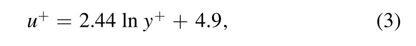
whereu+=u/uτrepresents the dimensionless flow velocity,y+=yuτ/ν represents the dimensionless wall distance,νrepresents the kinematic viscosity in air,anduτis the wall friction velocity.Deriving formula(3)further leads to the following:
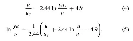
The relationship between the friction velocityuτiand the measured time-averaged sequence(yi,ui)can be obtained,where different values oficorrespond to different normal distances:
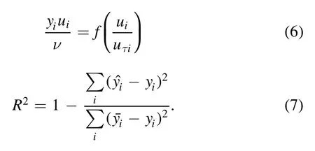
Equation(6)demonstrates that each time-averaged sequence(yi,ui)in the logarithmic layer corresponds to a certain friction velocityuτi,and only the values ofuτiare unknown.By applying least-squares regression to all the time-averaged sequences in the logarithmic region,the goodness of fit(R2)approaches 1,and the optimal friction velocityuτcan be obtained[29].
Through equations(6)and(7),the skin friction coefficientCfand WSS τw=ρuτ2can be obtained:

In equation(9),Rrepresents the TDR rate.WhenR>0,plasma actuation achieves a positive TDR;whenR<0,plasma actuation generates drag.τw-offrepresents the WSS at the measuring point without plasma actuation,whereas τw-onrepresents the WSS at the measuring point with plasma actuation.
To ensure that the area containing the actuator is located within the TBL,when the plasma actuator was not working,the velocity of the boundary layer was measured 10 mm downstream of the actuator at a wind speed of 9.6 m s-1.Figure 8 shows the velocity distribution of the boundary layer without plasma actuation.The velocity distribution within the logarithmic region(50<y+<200)of the boundary layer downstream of the actuator conforms to a classic logarithmic distribution,indicating that the boundary layer in the measurement area is a fully developed TBL.Therefore,the placement of a plasma actuator on the lower wall of the wind tunnel does not affect the natural development of turbulence in the measurement area.

Figure 1.Schematic diagram of the low-speed wind tunnel.
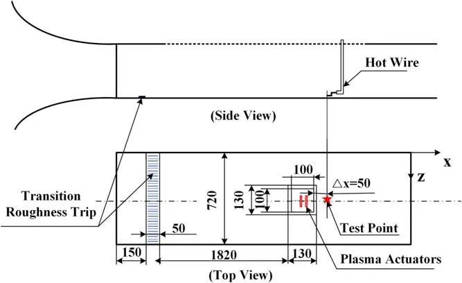
Figure 2.Schematic diagram of the experimental layout.

Figure 3.Pulse waveform diagram.
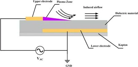
Figure 4.Schematic diagram of the DBD plasma actuator.

Figure 5.Schematic diagram of the installation of the blowing module.

Figure 6.Schematic diagram of the blowing TDR strategy.

Figure 7.The spatial location of the hot-wire anemometer.
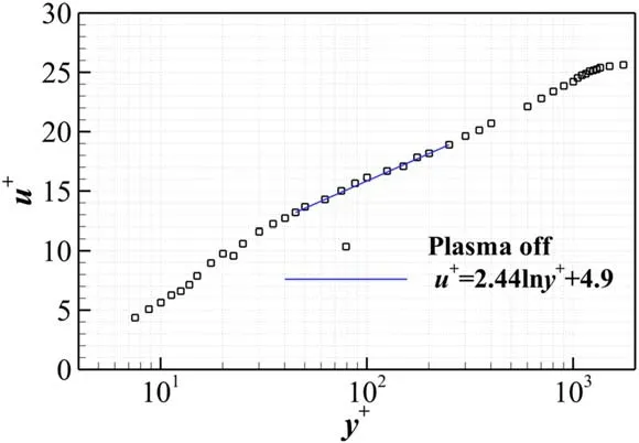
Figure 8.Influence of the arrangement of the plasma actuator on the TBL.

Figure 9.The deviation of friction velocity from the average value of five measurements and the corresponding fitting residuals.
3.2.Repeatability test
To verify the repeatability of the SBP-PA experiment,we kept the incoming velocity 9.6 m s-1(Re=1.445×10⁴),Vp-p=8 kV,τ=50%,fp=200 Hz,five repeated measurements were performed,and the corresponding friction speed was fitted.As shown in figure 9,the friction velocity deviationis measured five times,whereu τiis theith measurement value andis the average value of the five measurements.The confidence interval is from-0.0174 to+0.0174(m s-1),the root mean square(RMS)is 0.005 44(m s-1),and the RMS value is within the confidence interval,so the experiment is highly repeatable.
3.3.TDR experimental results with slot blowing pulsed plasma actuation
3.3.1.TDR effects under different duty cycles.Previous studies have found that a higher DBD actuation voltage corresponds to a stronger induced jet velocity and a longer jet distance;therefore,more energy can be injected into the TBL.This phenomenon is capable of interfering with self-sustaining near-wall streamwise vortices and coherent structures,and expected to further interfere with the structure of large-scale vortices in the outer region of the TBL,thereby regulating the influence of the structure of largescale vortices on the streamwise vortices within the inner boundary layer.However,the results of previous experiments indicate that more input energy to the plasma actuator does not correspond to a better outcome[18,30].First,an excessively high actuation voltage can cause the insulating layer of the plasma actuator to age prematurely;after the insulating layer ages,the equivalent resistance decreases,the internal current of the plasma actuator increases,and heat accumulates quickly on the surface of the insulating layer,which causes the plasma actuator to break down,catch fire,or begin arcing.Second,when the jet velocity induced by the plasma actuator is too high,after the jet flow merges with the incoming flow,a synthetic jet is generated at a certain angle to the main flow direction and easily causes the flow to separate from the wall.Third,the application of excessively strong plasma actuation on the near-wall surface may accelerate the growth of self-sustaining streamwise vortices,thereby increasing the WSS[18].Therefore,choosing the appropriate plasma actuation parameters according to external flow phenomena and the scale of the vortices is necessary for indepth study.
To study the influence of the SBP-PA with different energies on the WSS of turbulent flow and evaluate the change in the WSS of the TBL under different pulse duty cycles,the experiment in this paper maintained an incoming flow velocityU∞=9.6 ms-1,a peak-to-peak plasma actuation voltageVp-p=8kV,a pulse frequencyfp=100 Hz,and a carrier frequencyF=7.6 kHz.Figure 10 shows the TDR achieved by spanwise blowing under different duty cycles(τ=15%,30%,50%,70%,and 90%),and the error distribution of friction velocity fitting at 95%confidence,it can be found that the friction speed fittingR2under different duty ratios is close to 1,which indicates that the fitting accuracy is good and the results are accurate.It can also be concluded from the changing trend that the TDR rateRis not positively correlated with the duty cycle τ.When the duty cycle increases from 15% to 30%,the TDR rate greatly increases by 216.8%.When the duty cycle increases from 30%to 90%,the TDR rate first increases slightly and then gradually decreases.The highest TDR rate(Rmax=13.67%)appears at a duty cycle of 50%,while the lowest TDR rate(Rmin=11.78%)appears at a duty cycle of 90%.In the initial stage of flow control,the plasma actuation energy needs to be strong enough to meet the basic requirements of the flow control energy.However,when the plasma actuation energy is higher than a certain threshold(50%),the injection of more energy fails to improve the TDR effect;in fact,the outcome is a reduction in the TDR effect.Hence,it is essential to match the physical parameters between the energy being injected into the TBL and the scale of the flow being controlled.

Figure 10.The variation in the TDR rate under different duty cycles.
The plasma flow control mechanism closely relates to the vortex structure,and the duty cycle technique can produce a series of periodic vortex structures that enhance the flow field’s vorticity and momentum.Studies have shown that lowfrequency pulse actuation can generate a series of large-scale shedding vortices,leading to momentum mixing between the mainstream and the shear layer.In comparison,highfrequency pulse actuation causes small-scale vortices to promote the transition to mainstream[31].A new vortex is formed in the pulsed actuation mode at each pulse cycle.The vortices induced by pulsed actuation propagate faster than that of continuous actuation,and the vortex core velocity of pulsed actuation increases with the value of the duty cycle.
In this experiment,the duty cycle value represents the length of the discharge time in each pulse period,the period of duty-off is the development time of the induced vortices,and the period of duty-on is the evolution time of the induced vortices.When the duty cycle increases gradually,the duty-on time of the plasma actuator increases,the plasma density becomes more significant,and the discharge energy becomes more intensive.More energy will be injected into the flow field by the momentum transfer,which further promotes the formation of the induced vortex.
However,when the duty cycle increases beyond a certain threshold,the vorticity of the induced vortices decreases,the distance of adjacent vortices decreases,and the propagation mode gradually evolves from intermittent pulse to continuous mode[32,33].So,when the duty ratio is smaller,the interaction between the primary vortex and the residual vortexof the last cycle is negligible.The induced vortex can resist the residual vortex’s impact,maintain a complete vortex configuration,and control the boundary layer in a pulsed manner.On the contrary,when the duty ratio is larger,the interaction between the primary vortex and the residual vortex of the last cycle increases,and the vorticity of the primary vortex is not enough to resist the impact of the residual vortex.Thus,it is difficult to form a complete vortex,and the scale of the induced vortex cannot match the thickness of the viscous bottom layer,resulting in an efficiency decrease in drag reduction.
When the pulse duty cycle is greater than 30%,an increase in energy has little effect on the TDR effect of plasma actuation.Therefore,with the flow conditions remaining unchanged,a smaller duty cycle can be selected to improve the energy efficiency,which is more conducive to conserving energy and is therefore valuable for environmental protection applications.
Table 1 compares the changes in the boundary layer parameters under different duty ratios.When the duty ratio is less than 50%,uτi,WSS,andCfgradually decrease,and the TDR effect gradually increases;however,when the duty cycle

Table 1.Comparison of the related calculation parameters from different duty cycles at the measuring point.
τ≥50%,the TDR effect of the SBP-PA begins to gradually decrease.This analysis shows that when the duty cycle tends toward approximately 50%,the scale of vortices induced by the SBP-PA jet is close to the size of the turbulent near-wall streamwise vortices,and the blowing height is similar to the thickness of the viscous sublayer;thus,this process has a better inhibitory effect on self-sustaining near-wall streamwise vortices.However,when the duty cycle deviates from the optimal control parameter(τ≈50%),the energy produced by the SBP-PA and the scale of the induced vortices deviate from the energy and spatial scales of the current mainstream streamwise vortices,and the control effect is slightly reduced.In a future study,a high-frequency and high-spatial resolution flow visualization experiment will be carried out to further verify this inference.
3.4.TDR effects at different pulse frequencies
Previous plasma experiments discovered that a resonance-like phenomenon occurs when there is a coupling relationship between the pulse frequency of plasma actuation and the natural frequency of the incoming flow,and this phenomenon greatly enhances the plasma flow control effect[15].To obtain the optimal of plasma parameters,improve the effectiveness of the plasma actuator,and expand the application scope of plasma flow control engineering,based on the experimental results of the duty cycle described in our previous section,the influences of different pulse frequencies on the frictional drag of turbulent flow were studied in detail by maintaining an incoming flow velocityU∞=10 m s-1,with a peak-to-peak voltageVp-p=8 kV,and a duty cycle τ=50%.This analysis essentially demonstrates that the TDR effect of the plasma actuator on the TBL varies at different pulse frequencies(fp=50 Hz,100 Hz,and 200 Hz).
The movement of the hot-wire probe in the boundary layer is controlled by the three-dimensional measurement system,and the change in the velocity of the boundary layer before and after plasma actuation is measured 10 mm downstream from the center of the actuator(Δx+≈1253).Figures 11(a)-(c)compare the boundary layer velocity distributions measured by applying the SBP-PA with different pulse frequencies.According to the internal dimensions of the boundary layer(friction velocityuτand viscous length
lv=v/uτ,wherevis the kinematic viscosity),when the SBPPA is not applied,the velocity distribution is dimensionless.However,the velocity distribution of the boundary layer changes after applying different pulse frequencies,and the velocities of the buffer layer and the logarithmic region decrease significantly,resulting in a velocity reduction.After applying the SBP-PA,the blowing jet interacts with the flow near the wall,and the reverse vortex induced by the SBP-PA forms a kind of‘virtual barrier’effect near the wall;consequently,the streamwise vortices and coherent structures near the wall of the turbulent flow are lifted away from the wall,and the frictional drag induced by the interaction between the sweep events of the streamwise vortices is attenuated.At the same time,the regeneration of the near-wall streamwise vortices is suppressed,decreasing the velocity in the buffer layer and the logarithmic region,and ultimately reaching the goal of TDR.
Figure 11(d)compares the changes in the boundary layer velocity distribution under different pulse frequencies.When

Figure 11.Comparison of the boundary layer velocity distributions at different pulse frequencies:(a)fp=50 Hz;(b)fp=100 Hz;(c)fp=200 Hz;(d)velocity distributions at different pulse frequencies.
y+<125,applying the SBP-PA with different pulse frequencies triggers varying downward deviations in the velocity profile.As the pulse frequency continues to increase,the deviations in the velocities of the buffer layer and logarithmic region gradually increase;in other words,the viscous effect in the near-wall area gradually plays the dominant role in the inner area of the TBL.When 125<y+<400,the effects of different pulse frequencies are only marginally different,and the velocity distributions under the three pulse frequencies tend to be consistent.Wheny+>400,the velocity profiles of the boundary layer with and without plasma actuation essentially coincide,which indicates that the control effect of the SBP-PA is basically lost.The following conclusions can be drawn.(1)At different pulse frequencies,the TDR effect of the SBP-PA varies considerably,and there is an optimal pulse frequency.(2)The SBP-PA has a limited impact area,and the current actuator configuration affects mainly the structure and viscous effect of streamwise vortices near the wall in the viscous sublayer,buffer layer,and logarithmic layer.With increasing distance from the wall,the kinetic energy effect of the SBP-PA gradually weakens,making it difficult to affect the structure of large-scale vortices in the outer region of the turbulent flow.
Table 2 shows a comprehensive comparison of the distributions of various parameters of the boundary layer under different pulse frequencies.As the pulse frequency gradually increases,uτigradually decreases,leading to a gradual increase in the TDR rate.When the pulse frequencyfp=200 Hz(f+=2πfpd/U∞=7.196),the optimal local TDR rateRmax=16.97%.This also means that,whenf+=7.196,the jet frequency induced by the SBP-PA is closer to the natural frequency of the external mainstream;that is,the reverse vortex generated by a single pulse of the jet blowing through the slot is close to the spatial scale of the streamwise vortices near the wall,thereby producing the optimal TDR effect.It is worth noting that in this experiment,to prevent electromagnetic interference and protect the measurement and control equipment,the measuring position of the hot-wire probe in the boundary layer isΔx+≈1253 mm downstream of the plasma actuator.It can be inferred that the actual TDR rate measured in the near-wall area above the SBP-PA or at a distance less thanΔx+downstream of the SBP-PA will be greater than the TDR rate measured in the current position.Future experiments will employ noncontact technology to carry out near-wall turbulence measurements.

Table 2.Parameters measured under different actuation frequencies at the measuring point.
Figures 12(a)-(c)compare the velocity fluctuation distributions in the TBL measured by applying the SBP-PA with different pulse frequencies.Using the external dimensions of the boundary layer without plasma actuation,the velocity
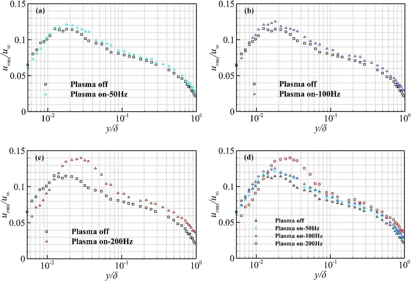
Figure 12.Distributions of the flow direction velocity fluctuations at different pulse frequencies:(a)fp=50 Hz;(b)fp=100 Hz;(c)fp=200 Hz;(d)velocity fluctuations with different fp.
fluctuation is dimensionless.In the range of 0<y/δ<0.0014,the three pulse frequencies all reduce the velocity fluctuation to varying degrees,which may be due to the SBP-PA uplifting the turbulent near-wall streamwise vortices and coherent structures,thereby weakening the interaction between the sweep events of streamwise vortices and the wall and reducing the velocity fluctuation in the near-wall region(buffer layer and logarithmic region).However,when 0.0014<y/δ<0.56,the velocity fluctuation increases to varying degrees,and the pulse frequencyfp=200 Hz greatly increases the velocity fluctuation.This may be because the SBP-PA control effect increases with rising pulse frequency,and the number of vortices generated by the coupling between the SBP-PA and the main flow increases,which enhance both the velocity fluctuation and the intensity of turbulence.Wheny/δ>0.56,the velocity fluctuation distribution basically tends to be the same;this trend is similar to the experimental results in the flow direction arrangement of the slot blowing TDR strategy[18].This comparison also shows that the pulse frequencyfp=200 Hz(f+=2πfpd/U∞=7.196)corresponds to the optimal TDR effect for the current flow.With increasing distance from the wall,the control effect of the SBP-PA gradually weakens,which further confirms that the effect of the SBP-PA is limited to only the buffer layer and logarithmic layer near the wall,whereas the plasma actuator is still unable to exert an influence on the structure of large-scale vortices in the outer region of turbulence flow.Figure 12(d)comprehensively compares the distributions of the velocity fluctuation in the boundary layer under different pulse frequencies,indicating that within the range of 0.0014<y/δ<0.56,a greater pulse frequency corresponds to stronger pulse enhancement.The slot blowing strategy increases the amplitude of the velocity fluctuation in the outer region but reduces the velocity fluctuations near the wall.This result is similar to the outcomes reported in the literature[15].
The increase of the pulse frequency will lead to more collisions between ions and electrons,which will increase the interaction between the induced vortices and the main flow,which may improve the flow control effectiveness.In this experiment,the drag reduction effect is also enhanced with the increase of the pulse frequency.Still,the ratio of TDR is not simply positively correlated with the pulse frequency.Reference[32]pointed out that DBD will reduce the vortex scale when the pulse frequency exceeds 200 Hz,and the vortex scale has a particular relationship with the TBL control.The control effect will be improved when the vortex scale is equivalent to the viscous bottom layer.Therefore,when the pulse frequency exceeds 200 Hz,the size of the vortex-induced by SBP-PA may be reduced,and then the drag reduction effect may be weakened.
From the view of time-averaged analysis,the low-and high-velocity streak structure in the near-wall region of the TBL is distributed randomly,which increases the velocity gradient in the near-wall region and generates high friction drag.In this paper,a method of TDR using SBP-PA was proposed by suppressing the streak structure in the near-wall region.When the SBP-PA is actuated,a series of induced vortices perpendicular to the wall is generated.They evolve into large-scale streamwise vortices(LSSV)in the near-wall region of the boundary layer.
The induced vortices perpendicular to the wall can inhibit the spanwise motion of the streak structure near the wall,thereby stabilizing the streak structure to act like riblets[34].Such riblets-like drag reduction effect can be called virtual riblets,which can suppress the interaction with the wall by inhibiting the development of the streamwise vortex and streak structure near the wall.Also,the virtual riblets can reduce the burst events of the vortex structure in the near-wall region of the TBL.
It is worth noting that,to make the virtual riblets play a more significant role in inhibiting streamwise vortices and low-velocity streaks,the scale of induced vortex structure should be on the same level as the thickness of the viscous bottom layer.If the scale of the induced vortex structure is larger than the thickness of the viscous bottom layer,the flow effect of SBP-PA is similar to rendering a series of large-scale streamwise vortex instead of virtual riblets.At this time,the LSSV generated by SBP-PA will be dominant,attenuating the drag reduction effect and increasing the turbulence intensity.Conversely,when the virtual riblets effect dominates,the drag reduction effect will increase,and the turbulence intensity can be reduced.In the future,our group will analyze the near-wall turbulent structures to verify the drag reduction mechanism of SBP-PA by using high-speed PIV and microimaging technology.
4.Conclusion
In this experiment,a plasma flow control strategy with a slot blowing configuration is adopted,and the flow control effect is measured by means of a hot-wire anemometer and a data acquisition system.Experimental research is carried out on the TDR in a low-speed wind tunnel to study the influence of an SBP-PA on the streamwise vortices and coherent structures near the wall of the TBL.The analysis reveals the following conclusions:
(1)Implementing the SBP-PA under different duty cycles indicates that the TDR effect is not positively related to the duty cycle.When the plasma actuation energy is higher than a certain threshold(50%),the injection of additional energy fails to improve the TDR effect and instead reduces the effect.
(2)At different pulse frequencies,the TDR effect varies considerably,and there is an optimal pulse frequencyfp=200 Hz(f+=7.196).The SBP-PA causes the jet flow to interact with the flow near the wall,induces a reverse vortex,uplifts the streamwise vortices and coherent structures near the wall of the turbulent flow away from the wall,and alleviates the frictional effect induced by the interaction between the sweep events of the streamwise vortices and the wall.At the same time,the regeneration of the near-wall streamwise vortices is suppressed,and the goal of TDR is finally achieved.
(3)The area over which plasma actuation exerts an influence is limited.The proposed SBP-PA affects mainly the structure of streamwise vortices near the wall in the buffer layer,viscous sublayer,and logarithmic region.With increasing distance from the wall,the kinetic effect of the plasma actuator gradually weakens,and it is difficult to affect the structure of large-scale vortices in the outer region of the turbulence flow.
This work systematically studies the TDR effects of an SBP-PA under different electrical parameters,the outcomes of which are pertinent to the ongoing development of adaptive intelligent control.In future work,our research group will combine microscopy and stereoscopic PIV(SPIV)with an SBP-PA to study the influences of streamwise vortices in the inner area of the TBL near the wall and large-scale coherent structures in the outer region.Combined with the results of wind tunnel experiments and computational fluid dynamics(CFD)simulations,the velocity fluctuation quadrant decomposition method will be used to study the influences of the position,arrangement,pulse frequency,and working phase of the plasma actuator on the coherent structures of turbulent flow under different incoming flows,especially the control laws of sudden phenomena such as the ejection and sweep events of streamwise vortices.Furthermore,plasma actuator configurations that can more effectively control large-scale coherent structures in the outer region of turbulence will be explored,and the regulation mechanism between the flow structures in the inner and outer regions of turbulence flow will be obtained.Ultimately,a method to optimize the TDR effect,the mechanism by which the TDR effect will be generated,and the parameter influences will be scientifically explained.
Acknowledgments
The present study is supported by National Natural Science Foundation of China(Nos.61971345 and 12175177)and the Foundation for Key Laboratories of National Defense Science and Technology of China(No.614220120030810).
猜你喜欢
杂志排行

Plasma Science and Technology的其它文章
- An equivalent model of discharge instability in the discharge chamber of Kaufman ion thruster
- Discharge and jet characteristics of gliding arc plasma igniter driven by pressure difference
- Investigation of stimulated growth effect using pulsed cold atmospheric plasma treatment on Ganoderma lucidum
- Comparative study of pulsed breakdown processes and mechanisms in self-triggered four-electrode pre-ionized switches
- Nanosecond laser preheating effect on ablation morphology and plasma emission in collinear dual-pulse laser-induced breakdown spectroscopy
- Interaction of an unwetted liquid Li-based capillary porous system with high-density plasma