Broadband and high efficiency terahertz metasurfaces for anomalous refraction and vortex beam generation
2022-10-26WenYuLi李文宇RanSun孙然JingYuLiu刘靖宇TianHuaMeng孟田华andGuoZhongZhao赵国忠
Wen-Yu Li(李文宇) Ran Sun(孙然) Jing-Yu Liu(刘靖宇)Tian-Hua Meng(孟田华) and Guo-Zhong Zhao(赵国忠)
1Department of Physics,Capital Normal University,Beijing Key Laboratory for THz Spectroscopy and Imaging,Key Laboratory of THz Optoelectronics,Ministry of Education,Beijing 100048,China
2Institute of Solid State Physics,Shanxi Datong University,Datong 037009,China
Keywords: terahertz,metasurface,anomalous refraction,vortex beam generation
1. Introduction
In the last decade, the metasurfaces used to control and manipulate the propagation of electromagnetic waves have received extensive attention.[1–6]Researchers have designed various patterns on the ultra-thin metal or dielectric, which are called unit cells or meta-atoms, to achieve the artificial adjustment of phase, amplitude and polarization of incident light.[7–16]As a result, via various different spatial arrangements for the unit cells, a diverse set of functional devices can be engineered to achieve an abnormal refraction,[17,18]diffraction-limited focusing,[19,20]photonic spin Hall effects,[21,22]vortex beams,[23–25]etc. Generally,vand c-shaped unit cells with equal amplitudes and a phase over 2πare typically used to construct various metasurfaces.[26,27]However, the conversion efficiency of the resonance metasurfaces is very low. The theoretical limit of the crosspolarization conversion efficiency of a single-layer metasurface is only 25%.[28]Since this kind of low efficiency is not feasible for the practical device implementation,the improvement of efficiency is one of the problems that researchers are committed to solve.
Metasurfaces composed of double-layer unit cells are often proposed, in which the Pancharatnam–Berry phase elements are used to convert the incident circularly polarized wave into the corresponding cross-polarized component.[29]In this case, the transmission efficiency is greatly enhanced due to the excitation of both the electric and magnetic response within the upper and lower layers of the unit cells. However,such a design has a major weakness in that only a single working frequency can be employed. In addition,the incident light is required to be circularly polarized. Considering these limitations, another proposed design involves multi-layer structures,in which a Fabry–Perot-like cavity with a high efficiency is utilized.[30–37]For example, Zhanget al.[35]used resonant Fabry–Perot-like unit cells to produce a high operation efficiency of 70% and a conversion efficiency of 89%, and a broadband multifunctional metasurface in a microwave range with a relative bandwidth of 66.7%. In the terahertz(THz)region, as reported above, the devices with high efficiency and broadband metasurface are rare. A typical example was provided in 2013,Gradyet al.[30]reported that a transmission relating to linear polarization converter, based on Fabry–Perot resonance, can achieve a polarization conversion efficiency greater than 50%in a frequency range between 0.52 THz and 1.82 THz. In addition, the proposed unit cells have a crosspolarization transmittance of only 45% and the efficiency of beam steering,arising from the unit cells,reaches a maximum value of 61%at 1.4 THz.Obviously,there remains much room for improvement in the efficiencies of these types of THz functional devices. Simultaneously,it is clear that a system based on high-efficiency broadband metasurfaces, which can also perform various functions,is highly valuable and an important field of research. Particularly,when it can be implemented in the THz frequency range, the device is suitable for linearly polarized incident THz waves.
In this paper,according to the Fabry–Perot resonance,we design a multilayered unit cell that acts as a broadband and high-efficiency linear polarization converter in the THz region.We recognize that a seemingly similar structure to a symmetric split ring and a cut wire,has been reported in Ref.[32]. In the previous work, a vortex phase plate was designed to operate in the microwave region;the near-and far-field characteristics of the generated vortex beam are then discussed. In contrast,we propose the unit cells as the functional elements that generate both a higher efficiency and a wider bandwidth in the THz band. According to the eight unit cells,we design an anomalous refraction metalens and a vortex phase plate with high efficiency of metasurfaces, which are flexible to control the generated wavefront over a broadband. Furthermore,by using these unit cells to construct a 0.9-THz ultra-broadband with a relative bandwidth of 95%, the metasurface devices with a high efficiency and a superior performance are designed. It proves that these metasurfaces can be used as an anomalous refraction metalens and a vortex phase plate. The simulation results show that this kind of anomalous refraction metalens can act as a beam splitter and as a linear polarization selector which is achieved by solely changing the direction of the incident wave. The simulated maximum error, compared with the theoretical results,is below 4.8%. The vortex phase plate is shown to be a good candidate for free-space communication due to its broadband,a weak divergence,and a high efficiency.
2. Design of unit cell and analysis
Following the discussion above,the proposed multi-layer structure is arranged according to a model of multiple plasmon resonances. The unit cell within the middle layer,shown in Fig. 1(a), is designed with the outer radiusrand widthwof the symmetric split ring, andαandβdenote the rotation and open angles of the ring, respectively. The periodpof the unit cell is set to be 110 μm. A multi-layer structure,which consists of three layers of metallic pattern, separated by two polyimide (PI) dielectric layers, is designed to operate in the THz region as shown in Fig. 1(b) where the middle layer as a functional element is shown in Fig. 1(a). All the metallic layers within the patterned metasurface are Au layers each with a thickness of 0.2 μm and a conductivity of 4.561×10⁷S/m. For each of the PI dielectric layers, its permittivity isε=εr+εii=3.5+0.01i and thickness is 35 μm.The upper layer and the lower layer are both composed of two one-dimensional metallic gratings,which are mutually orthogonal. The grating constantgis 22 μm and the width of the metal bar is 8 μm. The total profile thickness is about 70 μm,which equals 0.2λat a frequency of 0.9 THz.
The numerical simulations are performed by using the software of CST Microwave Studio. Figure 1(c) shows the transmission/reflection amplitudes of the unit cell of middle layer,in which the cross-polarized transmission amplitudetyxis less than 0.5 in a frequency range of 0.2 THz–1.6 THz.In order to increase the cross-polarization transmission without blocking the incidences of co-polarization,the orthogonal gratings are added to the upper layer and the lower layer of the unit cell of middle layer as shown in Fig. 1(b). The simulated amplitudes for the multi-layer structure are shown in Fig.1(d), showing thattyxis greater than 0.87 in a frequency range between 0.36 THz and 1.51 THz. It is clear that the multi-layer structure is an excellent candidate for a broadband and high-efficiency of linear polarization converter that operates in the THz region. As marked by the arrows in Fig.1(d),the wide working bandwidth and high conversion efficiency result from the superposition and interference of multiple polarization conversion peaks at around 0.37, 0.46, 0.74, 1.15,and 1.48 THz in the Fabry–Perot-like cavity. Besides, there is an sharp co-polarized reflection peak at 1.53 THz, and the corresponding cross-polarized transmission has a deep drop,which obviously limits the further broadening of the bandwidth. So, the bandwidth of this three-layer structure is limited by co-polarized reflections. We can design a better polarization conversion unit cell to eliminate co-polarized reflection in a wider frequency band to increase the working bandwidth. The influence of the dielectric losses of the PI layers on the cross-polarization transmission can also be discussed.The simulation results in Fig. 1(e) show that in a frequency band of 0.5 THz–1.4 THz, although the transmission amplitudes decrease slightly with the imaginary part of the permittivity of the PI increasing, the overall transmission amplitude remains above 0.8. In addition, the several minimum values of the transmission amplitudetyxin Fig. 1(d) correspond to the maximum peaks of the co-polarization reflectionrxx,indicating that the co-polarization reflection is the main influence on the cross-polarization transmittance of the designed multilayer converter.In short,in the design of this three-layer structure,the top grating and the bottom grating act as polarization selectors,and the middle layer functions as a polarization converter. The significant transmission of the cross-polarization is attributed to the resonance of the Fabry–Perot-like cavity,which induces the repeated reflection and transmission inside the structure. The device performance is limited by dielectric loss and co-polarized reflection, and it could be further improved by optimizing the structural design and using low-loss dielectric materials.

Fig.1. (a)The two-dimensional(2D)top-view of unit cell within the middle layer of multi-layer structure. (b)Schematic diagram of multi-layer structure.Curves of co- and cross-polarized transmission/reflection fields against the frequency of the x-polarized incident wave for (c) single layer unit cell within middle layer,(d)multi-layer unit cell. (e)Graph showing the amplitudes of co-and cross-polarized transmission/reflection fields of multi-layer unit cell for different imaginary parts of the permittivity of PI layers.
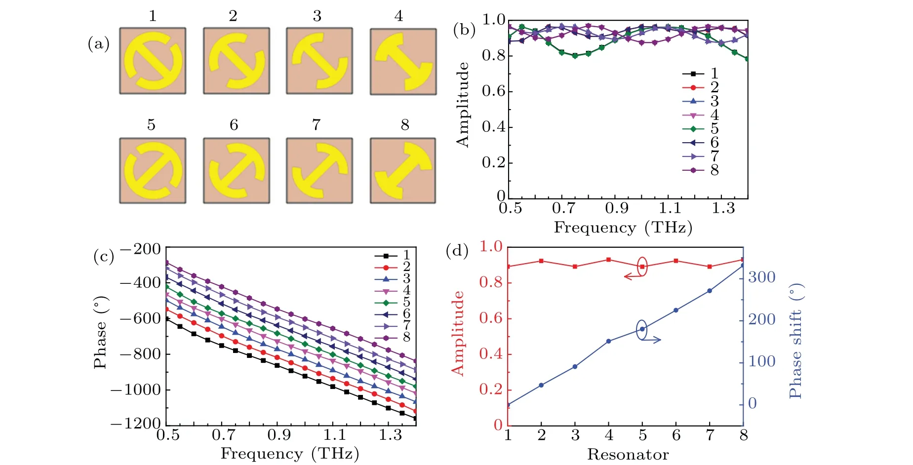
Fig.2. (a)Top view of eight unit cells within the middle layer, which have an incremental linear phase interval of π/4 between themselves.Variations of(b)amplitudes and(c)phases(in degrees)of cross-polarized transmission fields with frequency for the x-polarized incident waves in the eight multi-layer unit cells. (d)Phase shifts and amplitudes of cross-polarized transmittance with XLP incident wave at 0.9 THz, with red line denoting transmitted amplitude,and blue line referring to phase shift.
To achieve THz metasurfaces that operate in a broadband range with high efficiency,the designed unit cells need to possess the phase responses with the same slopes at different frequencies within a broad band range. Thus,the following condition needs to be satisfied:

wheref1andf2are the lower frequency and the upper frequency of the working band, respectively,fidenotes an arbitrary frequency within the band, andφ(x,y) is the phase of the transmission wave under normal incidence.[13]In this work,we design eight unit cells with similar amplitudes and a phase interval ofπ/4 as depicted in Fig.2(a).The unit cells 5–8 are rotated anticlockwise by 90°relative to the unit cells 1–4,respectively. The optimized structural parameters, the crosspolarized transmission amplitudes and efficiencies of the proposed unit cells with the eight characteristic phase values at a frequency of 0.9 THz are listed in Table 1. Using these eight
unit cells,many high-efficiency broadband THz functional devices can be constructed, as described in the following. Figure 2(b) shows the relationship between the cross-polarized transmission amplitudes of the eight unit cells and the frequency. As shown in Fig. 2(b), the cross-polarized transmission amplitudes show a set of slight fluctuations within about 10%for the eight unit cells,which are as high as 0.9 on average within the frequency range 0.5 THz–1.4 THz. Figure 2(c)indicates that the phase spectra of the cross-polarized transmission are close to their corresponding straight lines: these straight lines are almost parallel to each other , which supports the broadband performances. This working bandwidth ensures that the designed eight units produce only small amplitude fluctuations and keep the similar phase slopes. Thus,it is possible to design the metasurface devices with both a high efficiency and a wide bandwidth. The amplitudes and phases of the cross-polarized transmission fields that arise from the eight unit cells,underx-linearly polarized(XLP)incident waves at a frequency of 0.9 THz, are shown in Fig.2(d). It clearly indicates that the cross-polarized transmission fields have similar amplitudes about 0.9 and phases that cover the whole 2πrange. The eight unit cells have an incremental phase change ofπ/4 between themselves. Moreover, the maximum transmission efficiencies of the eight unit cells can reach as high as 86%, as indicated by the calculated result in Table 1. Therefore,they can be used as the functional elements for the construction of high-efficiency and broadband metasurface devices.

Table 1. Geometrical parameters, amplitudes, phases, and transmission efficiencies of eight different unit cells of multi-layer structure operating at 0.9 THz.
3. Anomalous refraction metalens
From the generalized Snell’s law(GSL)of refraction,the refraction angleθtof the transmitted cross-polarized component can be express as[27]

where dφ/dxis the gradient of the phase distribution at the interface,niandntrepresent the refractive indexes of incidence medium and transmissive medium, respectively,θiandθtare the incidence angle and the transmission angle, respectively.According to GSL, if we correctly design such a gradient of phase,the metasurface can refract light beams in any propagation direction.[18]
The proposed super-cell of the anomalous refraction metalens is composed of eight unit cells,which are repeated with a period of 880 μm in thexdirection and 110 μm in theydirection. In our design, the metalens has a phase increment change ofπ/4 between neighboring cells within a super-cell along thexaxis, while the unit cells are the same in theydirection. Periodic boundary conditions are applied to thexandydirections. At a frequency of 0.9 THz, the XLP wave is illuminated in a normal direction on the front of metalens. The resulting field distribution of the cross-polarized component,i.e., theycomponent, is shown in Fig. 3(a). It is determined that the transmitted beam deflects at an angle of 23.0°, while the theoretical value from GSL is 22.2°with an error of 3.6%.If the direction of the incident wave is changed, for example,the XLP waves illuminates the lower grating in a normal direction,it cannot pass through the device. However,they-linear polarized (YLP) waves can pass through the lower gratings.They are converted into XLP waves and transmitted out of the upper gratings. In this case,figure 3(b)shows that the refraction direction of the transmitted XLP waves bends towards the negative direction of thexaxis, while the deflection angle is the same as the scenario in the former case. Moreover,the polarization state of the incident wave and outgoing wave are interchanged. This indicates that the anomalous refraction metalens is dependent on the polarization state and the direction of the incident wave as well. As a result,we can use the metalens to select different linear polarizations solely by changing the direction of the incident wave. Moreover, the phase shift of the metasurface is changed fromπ/4 to-π/4 in the direction of thexaxis, meaning that the orders of the unit cells within a super-cell in thexaxis are inverted. The unit cells in theydirection remain unchanged. Figure 3(c) demonstrates that the outgoing beam deflects in the opposite direction compared with the scenario in Fig. 3(a), but the refraction angle is the same as in Fig.3(a).
Figure 4(a)shows the theoretically calculated and numerically simulated refraction angle as a function of frequency for the XLP incident wave. The anomalous refraction for the transmitted YLP component is simulated in a wide frequency band ranging from 0.5 THz to 1.4 THz. The simulated results well accord with the theoretical one with the maximum error below 4.8%.
Figures 4(b)–4(d)show the transmitted electric field distributions for the normal XLP incidence waves at 0.5 THz,1.0 THz, and 1.4 THz, respectively. The transmitted beams deflect respectively at angles of 45.0°,20.0°,and 13.5°. These angles are in good agreement with the theoretical values of 43.0°,19.9°,and 14.1°determined from Eq.(2). The simulations show that the metalens has excellent broadband characteristics,which are strictly dependent on the polarization state of the incident wave. It can be widely used as a beam splitter and as a linear polarization selector. The results indicate that a nearly perfect anomalous refraction of the beam can be realized by using the proposed metasurface.

Fig. 3. Transmitted electric field distribution for (a) metalens containing a phase increment change of π/4 along x axis, with XLP incident wave at a frequency of 0.9 THz,for(b)direction of the incident waves changed,with YLP wave being in normal direction incident on the lower gratings,and for(c)phase shift(-π/4)in x-axis direction.

Fig. 4. (a) Theoretically calculated and numerically simulated anomalous refraction angle versus frequency of the cross-polarized component. Transmitted electric field distributions, in which the XLP incident wave is at a frequency of(b)0.5 THz,(c)1.0 THz,and(d)1.4 THz.
4. Vortex phase plate
Another example of using the proposed eight unit cells is to design a vortex phase plate that can generate a vortex beam from the metasurface. The vortex beam is characterized by the spatial phase distribution, exp(ilφ), wherelis the topological charge andφis the azimuthal phase.[38,39]Vortex beams, which are also called orbital angular momentum (OAM) beams, have been employed in telecommunication systems due to their ability to increase data capacity and spatial efficiency.[40,41]Figure 5(a) shows the profile of the middle metallic layer of the metasurface. The dimension of metasurface is 1320 μm×1320 μm, which consists of an array of 12×12 unit cells that are divided into eight segments.Each segment is occupied by identical unit cells that possess the characteristics defined in Table 1. The incremental change of phase between two adjacent segments isπ/4 for a topological chargel=1. In the simulation, an XLP Gaussian beam is used to irradiate the metasurface. The intensity profile and phase distribution of the transmitted THz wave for 0.9 THz atz=-1500 μm are shown in Figs.5(b)and 5(c). A dark spot in the center of the intensity profile can be seen and the phase covers a 2πrotation counter-clockwise around the center. The mode purity (MP) of the generated vortex beam is important for this kind of device. It is defined as the ratio of power in the dominant mode to the overall power distributed across all of modes. This ratio is expressed as

whereAidenotes the magnitude of thei-th mode.[12]It is clearly seen in Fig. 5(d) that the calculated MP forl=1 at a frequency of 0.9 THz is 93.9%. This illustrates the high quality of the produced vortex beam.

Fig.5. (a)Cross-sectional profile of middle metallic layer of metasurface for generating a vortex wave beam with topological charge l=1. (b)Simulated intensity profile and(c)simulated phase distribution of metasurface at distance z=-1500 μm. (d)Simulated mode spectrum,in which the largest block relates to the generation of l=1 vortex beam at 0.9 THz.
The evolution of a normally incident XLP wave at a frequency of 0.9 THz through the metasurface ofl=1 is simulated. Figures 6(a) and 6(b) show the longitudinal amplitude and the field intensity of transmitted cross-polarized component. It is clearly seen that there are obvious interruptions and discontinuities along the normal direction, which is due to the existence of phase singularity in the center of the vortex beam. Moreover, the dark spot is stable, and a negligible divergence is observed in the propagation process. Figure 6(a)indicates that the opposite electric fields are observed on either side of the normal. It is due to the unit cells with the same cross-polarized transmission amplitude and a phase difference ofπbetween both sides of metasurface centered at the origin. Therefore,when an XLP wave irradiates the metasurface, the transmitted cross-polarizedycomponent has the opposing electric fields at the same positionzon the negative and positivexaxis,respectively. This kind of change can also be observed for the phase distribution in Fig. 6(c). It is seen that the phase is clearly divided into the left half and the right half in the propagation process. Undoubtedly, this is caused by the sudden change ofπin the phase on either side of the normal. In addition, the isophase lines are not horizontally parallel to the metasurface, while they are bent or distributed obliquely. This effect further confirms the presence of phase bending and the formation of vortex phase characteristics in the cross section. Moreover,it can be seen that the phase has obvious abrupt changes and the phase singularity always occurs centrally along the wave propagation. This explains why the dark spot in the center of the vortex beam is observed in the entire propagation process in Fig.6(b).

Fig.6. (a)Longitudinal amplitude,(b)field intensity,and(c)phase distribution at 0.9 THz for a transmitted YLP-THz vortex beam with l=1.
Figure 7 shows the calculated field intensities,phase distributions and mode spectra of the metasurface withl=1 under the normally incident XLP-THz waves from 0.5 THz to 1.4 THz. We can clearly observe here that all the intensity distributions at different frequencies show a typical doughnutshaped intensity with a singularity in the center,i.e.,the characteristics of a vortex beam.The spiral-like phase profiles covering a 2πrange are present in the phase distributions.The calculated mode purity of the vortex beam withl=1 is greater than 90% in the entire working bandwidth. The results further verify that the designed vortex phase plate, based on the eight unit cells, can generate nearly perfect vortex beams in a wide working range. In this work, an example to generate vortex beam with the topological chargel=1 is demonstrated as a kind of the feasibility. In fact, the higher order of vortex beams with topological chargesl >1 can also be generated by using a similar design.
Finally,the efficiencies of the designed metasurfaces can be calculated from the simulation results. The operation efficiency,η0,is determined from the following relationship:[35]

whereEtyis the simulatedy-polarized traverse electric field when the metasurface is inserted, andEixis thex-polarized field when the metasurface is removed. The polarization conversion efficiency,ηc, is defined as the ratio of the power carried by the cross-polarized transmission wave to the total power of the transmitted wave,[35,42]i.e.,

Here,pyx(pxx)is the power of the YLP(XLP)component for the transmitted field under the XLP incident wave. In the simulations, an electric field monitor of 1200 μm×1200 μm is used for the refraction metalens, which is positioned 800 μm away from the metalens. Similarly, the efficiency of vortex phase plate is calculated by employing a monitor with 1600 μm×1600 μm in size,which is positioned parallel to the plate at a distance of 1000 μm. For different frequencies,the calculated efficiencies of refraction metalens and vortex phase plate are presented in Fig.8. The results demonstrate that the calculated operation efficiencies and conversion efficiencies of the vortex phase plate are greater than 82%and 92%,respectively,in the entire frequency region 0.5 THz–1.4 THz. Moreover,the conversion efficiency as high as 95%is possible. For the designed refraction metalens,a high conversion efficiency of 88%can be obtained within the broad frequency range from 0.6 THz to 1.4 THz.At low frequencies,it can be seen that the operation efficiencies drop significantly. The lowest efficiency is about 55%, which is obviously lower than the counterpart of unit cell.

Fig.7. Simulated field intensity profiles at frequencies: (a)0.5 THz,(d)0.7 THz,(g)1.0 THz,(j)1.2 THz,and(m)1.4 THz;simulated phase distributions at frequencies: (b)0.5 THz,(e)0.7 THz,(h)1.0 THz,(k)1.2 THz,and(n)1.4 THz;simulated mode spectra at frequencies: (c)0.5 THz,(f)0.7 THz,(i)1.0 THz,(l)1.2 THz,and(o)1.4 THz.

Fig. 8. Curves of simulated operation efficiency and polarization conversion efficiency against frequency for both the refraction metalens and vortex phase plate.
The reasons may be as follows. Firstly,at these frequencies,the electromagnetic coupling between adjacent unit cells with different structural parameters is strengthened. Secondly,since each unit cell radiates and combines together at the different phases, they may not be phase-matched, so there will be a part of coherent cancelation. Finally,the large-angle deflection of the refracted beam and the wider beam width occur at low frequencies, which results in a much smaller energy for the transmitted cross-polarization component than for the incidentx-polarized waves. However, the operation efficiencies are all higher than 75% for the frequency ranging from 0.8 THz to 1.4 THz with a relative bandwidth of 55%. For comparison, in Table 2 listed also are the bandwidths and efficiencies of other related devices based on Fabry–Perot resonance. It is clear that our metasurface device has a higher efficiency and a wider bandwidth. The conversion efficiency is the largest. Therefore, this kind of device has significant advantages in practical applications.

Table 2. Comparisons of determined parameters among metasurface devices based on Fabry–Perot-like cavity structure.
5. Conclusions
In this work, two kind of broadband THz functional devices with three layers of metallic metasurface, a anomalous refraction metalens and a vortex phase plate,are designed and presented.The eight unit cells with high cross-polarized transmission efficiency in a broad frequency range from 0.5 THz to 1.4 THz are designed and optimized. Based on the configuration of the unit cells,the performance of designed anomalous refraction metalens shows the good consistence with the theoretical prediction, with a maximum error below 4.8%. The metalens shows both excellent efficiency and broadband characteristics. It can be used as a beam splitter and a selector of different linear polarization states. Furthermore, the designed vortex phase plate with a topological charge of 1 can efficiently generate nearly ideal vortex beams that exhibit high purity in the entire frequency band. The distribution of longitudinal electric field, and the intensity and the phase of the transmitted cross-polarized component are determined. The results indicate that a phase difference ofπarises on either side of the metasurface centered at the origin, which is the reason why a dark spot appears in the center of transmitted THz wave. The size change of dark spot is negligible in the forward direction. This work is try to provide a reference for the design and construction of highly efficient and broadband devices of metasurface.
Acknowledgements
Project supported by the National Natural Science Foundation of China (Grant No. 62071312), the National Key Research and Development Program of China(Grant No. 2021YFB3200100), the Important Research and Development Projects of Shanxi Province, China (Grant No. 201803D121083), and the Fund from the Shanxi Scholarship Council,China(Grant No.2020-135).
杂志排行

Chinese Physics B的其它文章
- Formation of high-density cold molecules via electromagnetic trap
- Dynamics of molecular alignment steered by a few-cycle terahertz laser pulse
- Terahertz spectroscopy and lattice vibrational analysis of pararealgar and orpiment
- Molecule opacity study on low-lying states of CS
- Finite-time Mittag–Leffler synchronization of fractional-order complex-valued memristive neural networks with time delay
- Ultrafast Coulomb explosion imaging of molecules and molecular clusters