Dynamically tunable multiband plasmon-induced transparency effect based on graphene nanoribbon waveguide coupled with rectangle cavities system
2022-08-31ZiHaoZhu朱子豪BoYunWang王波云XiangYan闫香YangLiu刘洋QingDongZeng曾庆栋TaoWang王涛andHuaQingYu余华清
Zi-Hao Zhu(朱子豪) Bo-Yun Wang(王波云) Xiang Yan(闫香) Yang Liu(刘洋)Qing-Dong Zeng(曾庆栋) Tao Wang(王涛) and Hua-Qing Yu(余华清)
1School of Physics and Electronic-information Engineering,Hubei Engineering University,Xiaogan 432000,China
2Wuhan National Laboratory for Optoelectronics,Huazhong University of Science and Technology,Wuhan 430074,China
Keywords: plasmon-induced transparency(PIT),graphene,group index,rectangle cavities
1. Introduction
Electromagnetically induced transparency (EIT)effect,[1,2]a quantum effect, which is caused by the destructive interference between the two different pathways excited in the so-called three-level atomic systems,[2]has shown various potential applications in fields,such as slowing light,[3,4]light storage,[5]and optical filtering.[6]However, effective nonlinear materials and rigorous conditions are difficult to be achieved, thereby significantly limiting the integrated application in practical optical devices. However, the plasmoninduced transparency(PIT)effect obtained by the cavity coupled with a plasmonic waveguide systems has caused extensive attention on account of simple realization. The devices realizing the PIT effect can be fabricated with a small footprint because surface plasmon polaritons (SPPs) can support deep subwavelength scale modes and overcome classical diffraction limit.[7–9]At present, diversified structures of PIT effect realization have been proposed. Moreover, the cavities sidecoupled with a waveguide and the bright-dark mode coupling methods are of special guidance for generating a PIT window in various structures;[10–13]these methods are beneficial to onchip integration plasmonic devices, thereby facilitating easy fabrication of an ultra-compact structure.
Thus far,many plasmonic devices for realizing PIT effect have been investigated,and the cavities coupled with a metaldielectric-metal (MDM) plasmonic waveguide is particularly prominent in highly integrated devices. Moreover, the coupling of MDM waveguides with double U-cavity,[14]doublestub cavities,[15]and double-disk cavities[16]have a great deal of research in the area of integrated slow light devices. However, only structural parameters can be adjusted once the devices are designed. Thus, obtaining dynamically tunable PIT effects at a specific wavelength is difficult. Graphene, a novel two-dimensional (2D) material for tunable optical devices, comprises a single layer of carbon atoms; it has been recently widely considered by researchers due to its advantages of dynamic tunability, strong locality, and low loss.[17]The Fermi level of graphene can be flexibly controlled by applying varying applied voltage. Therefore, this feature provides graphene with an advantage for new tunable photonic device materials. Thus, many PIT devices made of graphene with excellent slow light properties and dynamic tunability,such as plasmonic waveguide coupled with nanocavities,[18,19]metamaterials,[20–23]and metallic grating coupled with a dielectric waveguide layer(GCDWL)structures,have been proposed due to these unique performance advantages. Among of the various graphene structures,fabricating metamaterials and GCDWL structures through the current fabrication process is relatively complicated on accountof the limitation of the micro machining etching accuracy.[24]Furthermore, integrating metamaterials and GCDWL structures into the plasmonic chip is complicated.[25,26]
Compared with complicated metamaterials and GCDWL structures, the graphene nanoribbon waveguide structure has obtained widespread attention and achievements because of its easy integration,ultranarrow bandwidth,high transmission,and relatively simple fabrication.[27–29]For instance,Luet al.have numerically and theoretically investigated the plasmonic resonant effect and propagation characteristics by changing physical parameters such as the chemical potential and width of the graphene nanoribbon in a nanoscale graphene waveguide system consisting of a monolayer graphene nanoribbon coupled with two guided-wave graphene sheets,which provide a new way toward the realization of nanoscale mid-infrared spectral control and graphene plasmonic devices.[30]A dynamic tunable PIT effect is achieved in our structures inspired by this research. Wanget al.proposed tunable PIT effect based on Fabry–Perot resonance in a system by using two rectangle graphene cavities coupled with a graphene nanoribbon waveguide, which causes a relatively wide transmission window.[31]Noualet al.designed a compact graphene-based waveguide coupled to two rectangular cavity structures comprising graphene nanoribbons. In addition, the peak of the PIT window is less than 0.6 in this structure.[32]Zhaoet al.reported that graphene nanoribbon systems comprise a graphene strip loaded with a complex structure of graphene stub and ring cavity, thereby obtaining a considerably sharp PIT window. However,only a single-band PIT effect is acquired in the system.[33]Therefore,a dynamic tunable multiband PIT effect realized by graphene nanoribbon waveguide structure in the THz band remains relatively challenging.
For the fabrication of the graphene nanoribbon waveguide, it should be noticed that lithographic patterning lacks atomic resolution,which causes a mixture of armchair edges,zigzag edges, and dangling bonds; results in high lineedge roughness; and functionalizes the graphene nanoribbon edges.[34]Such inhomogeneities and disorder lead to severely degraded carrier mobility and thermal conductivity, coulomb blockade, and high off-currents-with effects that become increasingly detrimental with decreasing the graphene nanoribbon width.[34]Due to the fabrication defects of graphene resonators and nanoribbon waveguides, radiation loss and so on, the measuredQvalue and group index are usually much smaller in real experiments. Obviously,it is necessary to control the defects formation and the width edge roughness of the graphene nanoribbons in the nano-patterning process. Therefore,some important progresses have been reported. Wanget al.devised a gas phase chemical approach to etch graphene from the edges without damaging its basal plane. The reaction involved high temperature oxidation of graphene in a slightly reducing environment in the presence of ammonia to afford controlled etch rate(≤1 nm/min). 20 nm–30 nm wide graphene nanoribbon waveguides are fabricated lithographically,and used the gas phase etching chemistry to narrow the ribbons down to<10 nm.[35]Wanget al.showed that two kinds of experimental techniques consisting of electron–beam sculpting and Joule heating were adopted and about 10-nm wide graphene nanoribbon waveguide was obtained.[36]The thinnest graphene nanoribbon structure obtained is about 1.6-nm wide with an estimated transport gap of about 400 meV.[36]
Inspired by this basic research, a dynamically tunable multiband PIT effect based on the graphene rectangle cavities coupled with a graphene nanoribbon waveguide is proposed by tuning the Fermi level of the graphene rectangle cavity. Two methods based on different physical mechanisms are used to realize a single-PIT effect; one is the bright and dark mode couplings through direct destructive interference,and the other is the cavity coupled with a graphene nanoribbon waveguide through indirect destructive interference. Moreover,dual-and triple-PIT effects are predicted in this ultra-compact structure,whereas the corresponding group indexes are controlled from 143.2 to 108.6 and 161.4 to 115.8. The problems on the PIT window with low transmission, single band, and untunability in plasmonic waveguide devices applied to integration can be worked out particularly well,thereby demonstrating a new door for the dynamic tuning of slow light and dynamically tunable multichannel light storage devices.
2. System model design and theoretical analysis
Figure 1 shows four types of models,which comprise remarkable graphene rectangle cavities and a graphene nanoribbon waveguide.The width of the graphene nanoribbon waveguide is only 10 nm in the PIT system because only the edge mode of the SPPs on the graphene nanoribbon is considered. In order to compensate for the difference between SPPs and vacuum wave vectors, the light source is coupled to the graphene nanoribbon waveguide through a grating or prism.In practical applications, a diffraction grating can be etched in the front of the waveguide to couple the light source into the graphene nanoribbon waveguide. In our paper, the edge modes are achieved by the transverse magnetic (TM) polarized SPPs modes placed in thexdirection of the PIT system in Fig. 1. The incident light wave is restricted to travel forward in the waveguide when the incident light is injected and travels in the waveguide. SPPs are coupled into the graphene rectangle cavity as the SPP wave passes through the cavity–waveguide coupling region due to the near-field coupling. The graphene nanoribbon waveguide and rectangle cavities are placed on a 200-nm thick sapphire substrate to avoid substrate loss in the mid-infrared band. Only propagation loss as low as 1.9 dB/cm at 5.18 µm are caused in silicon-on-sapphire(SOS)waveguide.[37]Al2O3is selected as the substrate material mainly because of the low loss of SPPs that traveled on the sapphire in the THz band.[37]The refractive index of Al2O3and Si are set as 1.59 and 3.95 used in the simulations,respectively. Here,the transmission spectrum of four types of models are simulated by using the finite-difference time domain(FDTD)method, and the calculated boundaries for structures are employed by the perfectly matched layer.
The length of the rectangle cavity iswa=wb=wc=wd=140 nm,and the width of the rectangle cavity isda=db=dc=dd= 20 nm.[17]In addition, the coupling distance between the rectangle cavities and the graphene nanoribbon waveguide isla2=15 nm,lb1=lb2=15 nm,lc1=lc2=lc3=15 nm,ld1=ld3=15 nm,and that between the bright and dark modes isla1=ld2=ld4=20 nm.[17]The simulation results reveal that the Fermi level of the graphene nanoribbon waveguide is constantly maintained at 0.40 eV, and the Fermi level of the graphene rectangle cavity is tuned by changing the applied voltages.

Fig. 1. The schematic diagram of the proposed two-cavity-coupled system[(a) and (b)], three-cavity-coupled system (c), and four-cavity-coupled system(d).
The conductivity of the single-layer grapheneσgcan be expressed by Kubo formula, which represents the sum of the interband and intraband contributions:σg(ω)=σinter(ω)+σintra(ω). The specific expression is as follows:[38]
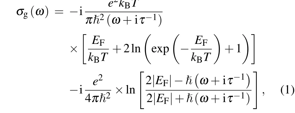
where i,T,kB,e,τ, and ¯hrepresent the imaginary unit,the temperature,the Boltzmann constant,the electron charge,the carrier relaxation time, and the Planck constant, respectively.ωis the angular frequency,EFis the Fermi level of the graphene,and the main contributions ofσgare from the intraband electron–photon scattering, whereas those ofσgcan be negligible from the direct transitions of the interband electron.Therefore,the conductivityσgof monolayer graphene can be obtained as a Drude-like expression after simplification[38,39]


wherek0andη0are the wavenumber and the impedance in the free space,respectively. Therefore,the effective refractive index is expressed byneff=β/k0, and the intrinsic quality factor isQint=Re(neff)/Im(neff).[36]Figure 2 shows the relationship of variation between the intrinsic quality factor and wavelength at various Fermi levels of the graphene. The intrinsic quality factor decreases with the respective increase in wavelength and the Fermi level of the graphene for the same wavelength,as shown in Fig.2.
Graphene has an unparalleled advantage compared with noble metals due to its dynamic tunability. It is very easy to realize the Fermi level tuning via gate voltage,as described by the following formula:[38]

wheredsubis the length between the graphene rectangle cavity and the substrate of Si,ε0is the vacuum permittivity,εdis the relative permittivity of dielectric silicon,andVgis the applied bias voltage. This equation shows that the Fermi level of the monolayer graphene can be dynamically tuned by the bias voltage.
The Fermi level of the graphene rectangle cavity is tuned from 0.39 eV to 0.44 eV to obtain dynamically tunable and multiband PIT effect and multichannel slow light. The resonant wavelength of the graphene rectangle cavity can be expressed as follows:[17]

whereWis the coupling length between the graphene nanoribbon waveguide and the rectangle cavities,ϕis the phase shift due to the reflection of the incident light in the cavity,andmis an integer.
3. Simulation results and discussion of single-PIT effect in bright and dark mode coupling systems
Figure 1(a) shows that the two-cavity-coupled system comprises rectangle cavity 1, rectangle cavity 2, and the graphene nanoribbon waveguide. The Fermi level of graphene rectangle cavities 1 and 2 is initially set as 0.40 eV and 0.42 eV,respectively. The bright mode can be directly activated by the SPPs wave, whereas the dark mode can be indirectly excited by the bright mode. In addition, the light can be coupled back to the bright mode, which results in the higher coupling strength between rectangle cavity 1 and graphene nanoribbon waveguide than that between cavity 2 and the waveguide. Therefore, cavities 1 and 2 behave as bright and dark modes,respectively.[40]Notably,the graphene-based nanoribbon waveguide, the graphene rectangle cavity 1, and the graphene rectangle cavity 2 can serve as the bare element|1〉, the dipole-allowed element|2〉, and the metastable element|3〉, respectively.[41]Two optical pathways, namely,|1〉→|2〉and|1〉→|2〉→|3〉→|2〉,are observed in the proposed bright and dark mode coupling system. The bright cavity 1 and dark cavity 2 induce the transmission peaks because of the destructive interference with each other.
Figure 3 shows a schematic of the realizing principle according to the coupled mode theory(CMT)of the single-PIT effect in bright and dark mode coupling systems.The coupling mode equation is calculated,the single-PIT phenomena are analyzed, and the transmission and coupling loss of light wave are ignored. The dynamic equation of cavity mode amplitudeai(i=1,2)for the time-harmonic field e−jωtis as follows:[40]


Fig.3. The schematic diagram showing the realization of the principle of the single-PIT effect in bright and dark mode coupling systems.
The conservation of energy indicates that the output wave amplitude of each cavity can be expressed as follows:[41]


wherec,vg,andlare the vacuum velocity of incident light,the group velocity,and the coupling length of monolayer graphene nanoribbon waveguide system,respectively.
The transmission spectra of the single-PIT effect under various graphene Fermi levels in bright and dark mode coupling systems are shown in Figs.4(a1)–4(d1). The Fermi level of cavity 1 is constantly maintained asEF1= 0.40 eV, while that of cavity 2 is set at different valuesEF2=0.39,0.40,0.41,and 0.42 eV. The transmission peak has an evident blue shift as the Fermi level of cavity 2 increases,and that of the PIT effect becomes slightly high,as shown in Figs.4(a1)–4(d1).The data of the FDTD and CMT calculation are highly consistent.Consequently,the single-PIT effect can be dynamically tuned in this structure by tuning the Fermi level of cavity 2. Figures 4(a1) and 4(d1) show that the transmission peaks of the PIT effect are 58%and 66%when the Fermi level of cavity 2 is 0.39 eV and 0.42 eV,respectively.Therefore,the high transmittance of the single-PIT effect is maintained when the Fermi level of the graphene rectangle cavity is tuned from 0.39 eV to 0.42 eV. This finding indicates that the dynamically tunable single-PIT effect can be obtained by adjusting the Fermi level of the graphene rectangle cavity 2.
Figure 4(a2)–4(d2) show transmission phase shift responses and group index under various graphene Fermi levels(from 0.39 eV to 0.42 eV) in bright and dark mode coupling systems. Figures 4(a2)–4(d2)show that the phase shift is 2mπat the peak wavelength because the dispersions are strong in the transparent wavelength.The group index at the peak wavelength and the transmission peak wavelength of the PIT effect decrease with the increase of graphene Fermi level of cavity 2,as shown in Figs.4(a2)–4(d2). Meanwhile,the intensity of the PIT transparent peak slightly decreases as the group index increases. This trend may be due to the additional time spent by the signal light in both rectangle cavities,thereby resulting in increased light power loss by scattering due to the resonance in the cavities.The group indexes of the peak wavelength are 74.9,71.7,69.6,and 66.1 with the graphene Fermi level of cavity 2 of 0.39,0.40,0.41,and 0.42 eV,respectively,as shown in the black dots of Figs.4(a2)–4(d2).
Figure 5 shows that the magnetic field simulation of|Hz|2is depicted at the transmission peak wavelength to further understand the bright and dark mode coupling mechanism of this structure. This figure also reveals the magnetic field distribution at the peak wavelength of 6420 nm when the Fermi level of cavities 1 and 2 are set to 0.40 eV and 0.42 eV,respectively,and the corresponding transmission spectrum of the PIT effect is shown in Fig. 4(d1). The bright cavity is directly excited, whereas the dark cavity is activated by coupling with the bright one. Hence,only the dark cavity is efficiently activated,whereas the bright cavity is evidently suppressed at the transmission peak. Similar to the EIT effect in atom systems,canceling of the bright cavity is attributed to the destructive interference caused by two optical pathways from graphene nanoribbon waveguide to the graphene rectangle cavity.
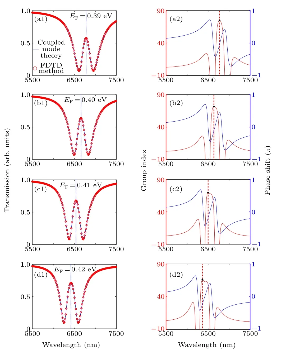
Fig. 4. Single-PIT effect simulation analysis of bright and dark mode coupling systems.(a1)–(d1)Transmission spectra of single-PIT effect.(a2)–(d2)Corresponding transmission phase shift responses and group index.
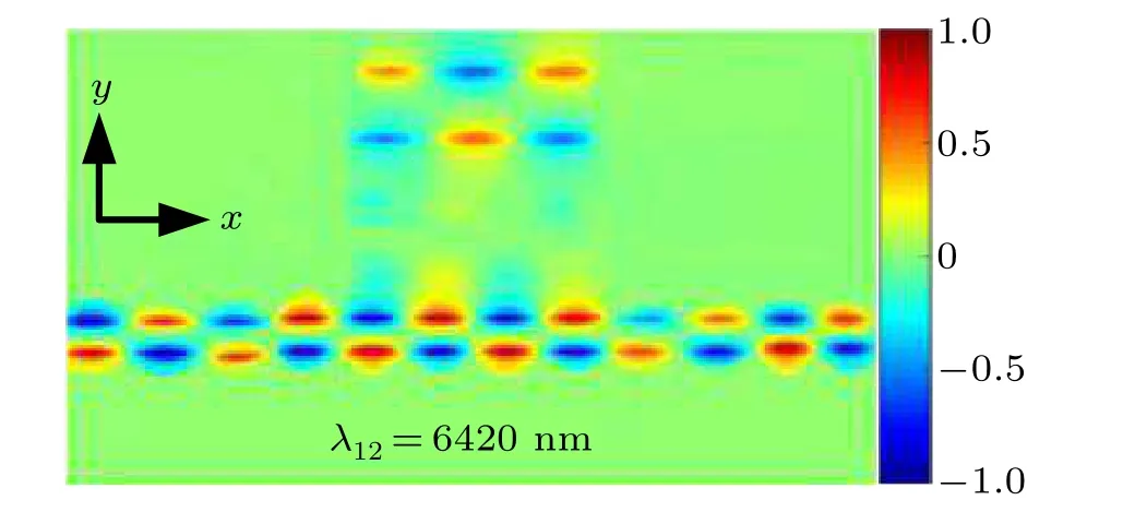
Fig. 5. |Hz|2 magnetic field distributions of the single-PIT effect in bright and dark mode coupling systems at the transparent wavelength.
4. Simulation results and discussion of single-PIT effect in two cavities side-coupled with waveguide system
Figure 1(b)shows that the PIT system comprises rectangle cavities 1 and 2 side-coupled with a graphene nanoribbon waveguide. The Fermi levels of graphene rectangle cavities 1 and 2 are initially set to 0.40 eV and 0.44 eV, respectively.Figure 6 reveals the analysis of the dynamic transmission features for two cavities side-coupled with a graphene nanoribbon waveguide system using a temporal CMT.The normalized amplitudeaifor the time-harmonic field e−jωtof theith cavity(i=1,2)for the time-harmonic field e−jωtis provided by the following expressions[16]


Fig. 6. Schematic diagram showing the realization of the principle of the single-PIT effect in two cavities side-coupled with a graphene nanoribbon waveguide.


wheretbis the transmission coefficient of two graphene rectangle cavities side-coupled with a graphene nanoribbon waveguide system, andφis the phase shift between two rectangle cavities.

Fig. 7. Single-PIT effect simulation analysis of two cavities side-coupled with a graphene nanoribbon waveguide system. (a1)–(d1) Transmission spectrum of the single-PIT effect. (a2)–(d2) Corresponding transmission phase shift responses and group index.
Figure 7 shows the results of the transmission spectra,corresponding transmission phase shift responses, and group index under different graphene Fermi levels (from 0.41 eV to 0.44 eV). The resonant wavelength of rectangle cavity 2 is blueshifted as the graphene Fermi level of cavity 2 increases, and the wavelength detuning between the two cavities increases. The PIT peak wavelength blueshifts because of the reduction in effective refractive index. The transmission spectrum shows a PIT peak because of the strong coupling between two cavities and the phase shift value of 2mπ(wheremis an integer). Figures 7(a2)–7(d2) show that the transmission phase shift is 0πat the peak wavelength due to the Fabry–Perot resonance. Figures 7(a1)–7(d1)reveal the gradual increase in transparent peak as the wavelength detuning increases, indicating an increase in coherent interference between the two rectangle cavities. Figure 7(a1) proves that the bandwidth is ultranarrow when the graphene Fermi level of cavity 2 is 0.41 eV, and a low PIT peak is obtained. Figure 7(d1)shows that the bandwidth reaches a maximum when the graphene Fermi level of cavity 2 is increased to 0.44 eV,and the peak value of PIT reaches 62%. This result indicates that strong destructive interference is achieved between the two rectangle cavities.
The maximum delay of this PIT system is inversely proportional to the bandwidth of transmission because of the principle of the delay bandwidth product, resulting in a tradeoff between the group index and wavelength detuning. Thus,the group index decreases as the wavelength detuning increases at the peak wavelength,as indicated in Figs.7(a2)–7(d2). Meanwhile, the intensity of the PIT transparent peak decreases as the group index increases. This phenomenon is due to the additional time spent by the signal light in both rectangle cavities,resulting in increased light power loss by resonance in the cavities. The group indexes of the peak wavelength are 79.2,53.2,37.4,and 28.3 with the graphene Fermi levels of cavity 2 of 0.41,0.42,0.43,and 0.44 eV,respectively,as shown in the black dots of Figs.7(a2)–7(d2).
Figures 8(a)–8(c)show that the magnetic field simulation of|Hz|2is depicted at the transmission peak and the two dip wavelengths to further understand the coupling mechanism of this structure. Figure 8(a)demonstrates the magnetic field distribution at the resonance wavelength of cavity 1 at 6650 nm when the Fermi levels of cavities 1 and 2 are set to 0.40 eV and 0.44 eV,respectively.Figure 8(b)shows the magnetic field distribution at the peak wavelength of the PIT effect at 6256 nm,and the corresponding transmission spectrum of the PIT effect is presented in Fig.7(d1).Figure 8(c)shows the magnetic field distribution at the resonant wavelength of cavity 2 at 5983 nm.The results show that Fabry–Perot resonance exists between the two rectangle cavities.

Fig.8. |Hz|2 magnetic field distributions of the single-PIT effect in two cavities side-coupled with a graphene nanoribbon waveguide system at the resonance wavelength.
Table 1 shows the maximum transmission and group index of the single-PIT system under different Fermi levels of graphene rectangle cavities at the peak wavelength of PIT.The maximum transmission of the single-PIT effect of bright and dark mode coupling systems is tuned from 58% to 71% due to the changing Fermi level of the graphene rectangle cavity 2 from 0.39 eV to 0.42 eV, and the group index is controlled between 74.9 and 66.1. This condition indicates that a fine-tuning method of the group index can be obtained in this PIT system. Alternatively, the maximum transmission of the single-PIT effect of two cavities side-coupled with a graphene nanoribbon waveguide system is tuned from 10%to 62%due to the changing Fermi level of the graphene rectangle cavity 2 from 0.41 eV to 0.44 eV, and the group index is controlled between 79.2 and 28.3. This condition indicates that the group index is tuned in a large tuning range by dynamically tuning the Fermi level of the graphene rectangle cavity. These results can be effectively applied to dynamically tunable light storage and slow light devices.

Table 1. Maximum transmission and group index of the single-PIT system under different Fermi levels of graphene rectangle cavities at the peak wavelength of PIT.
5. Simulation results and discussion of dual-PIT effect in triple cavities side-coupled with a graphene nanoribbon waveguide system
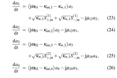
Figure 1(c) shows that the dual PIT system comprises rectangle cavity 1,cavity 2,cavity 3,and a graphene nanoribbon waveguide. The graphene rectangle cavity 1, cavity 2,and cavity 3 have an initial Fermi level of 0.42, 0.43, and 0.44 eV,respectively. Figure 9 shows that the dynamic transmission features for triple graphene rectangle cavities sidecoupled with a graphene nanoribbon waveguide system are analyzed by a temporal CMT. The normalized amplitudeaifor the time-harmonic field e−jωtof thei-th cavity(i=1,2,3)are analyzed by the following


whereωi(i= 1, 2, 3) represents the intrinsic resonant frequencies of the three cavities,κint,i(i=1, 2, 3)is the attenuation ratio of thei-th rectangle cavity,andκw,i(i=1,2,3)is the attenuation ratio due to energy coupling into the graphene nanoribbon waveguide.
The conservation of energy indicates that the output wave amplitude of each rectangle cavity can be analyzed(i=1,2),as follows:

whereφ1is the transmission phase shift between cavities 1 and 2,andφ2is the transmission phase shift between cavities 2 and 3(φ1=φ2=φ).
The output transmitted efficiency for triple graphene rectangle cavities side-coupled with a graphene nanoribbon waveguide system can be analyzed as follows:

whereα1=j(ω −ω1)+κint,1,α2=j(ω −ω2)+κint,2,α3=j(ω −ω3)+κint,3;tcis the transmission coefficient of triple graphene rectangle cavities side-coupled with a graphene nanoribbon waveguide system.
FDTD simulations revealed that the corresponding resonant wavelengths of rectangle cavities 1,2,and 3 are[6815,6625,and 6435 nm],[6650,6460,and 6270 nm],[6483,6293,and 6103 nm], and [6324, 6134, and 5944 nm] when Fermi levels of graphene rectangle cavities 1, 2, and 3 are [0.39,0.40,and 0.41 eV],[0.40,0.41,and 0.42 eV],[0.41,0.42,and 0.43 eV],and[0.42,0.43,and 0.44 eV].The corresponding intrinsic quality factors are presented in Fig.2. The total quality factors are caused by the following two PIT transparent peaks.The total quality factorQtof the graphene rectangle cavity can be calculated fromQt=λ0/∆λ,whereλ0and ∆λare the peak wavelength and full width at half maximum of the reflection spectrum,respectively. Therefore,the corresponding coupling quality factors of rectangle cavities 1,2,and 3 can be obtained in accordance withQw=QintQt/(Qint−Qt),as shown in Table 2.

Fig. 9. Schematic diagram showing the realization of the principle of the dual-PIT effect in triple cavities side-coupled with a waveguide system.
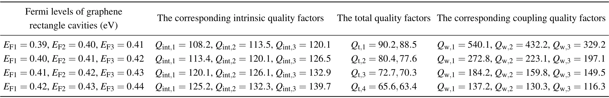
Table 2. Qint, Qt, and Qw under different Fermi levels of graphene rectangle cavities in triple cavities side-coupled with a graphene nanoribbon waveguide system.


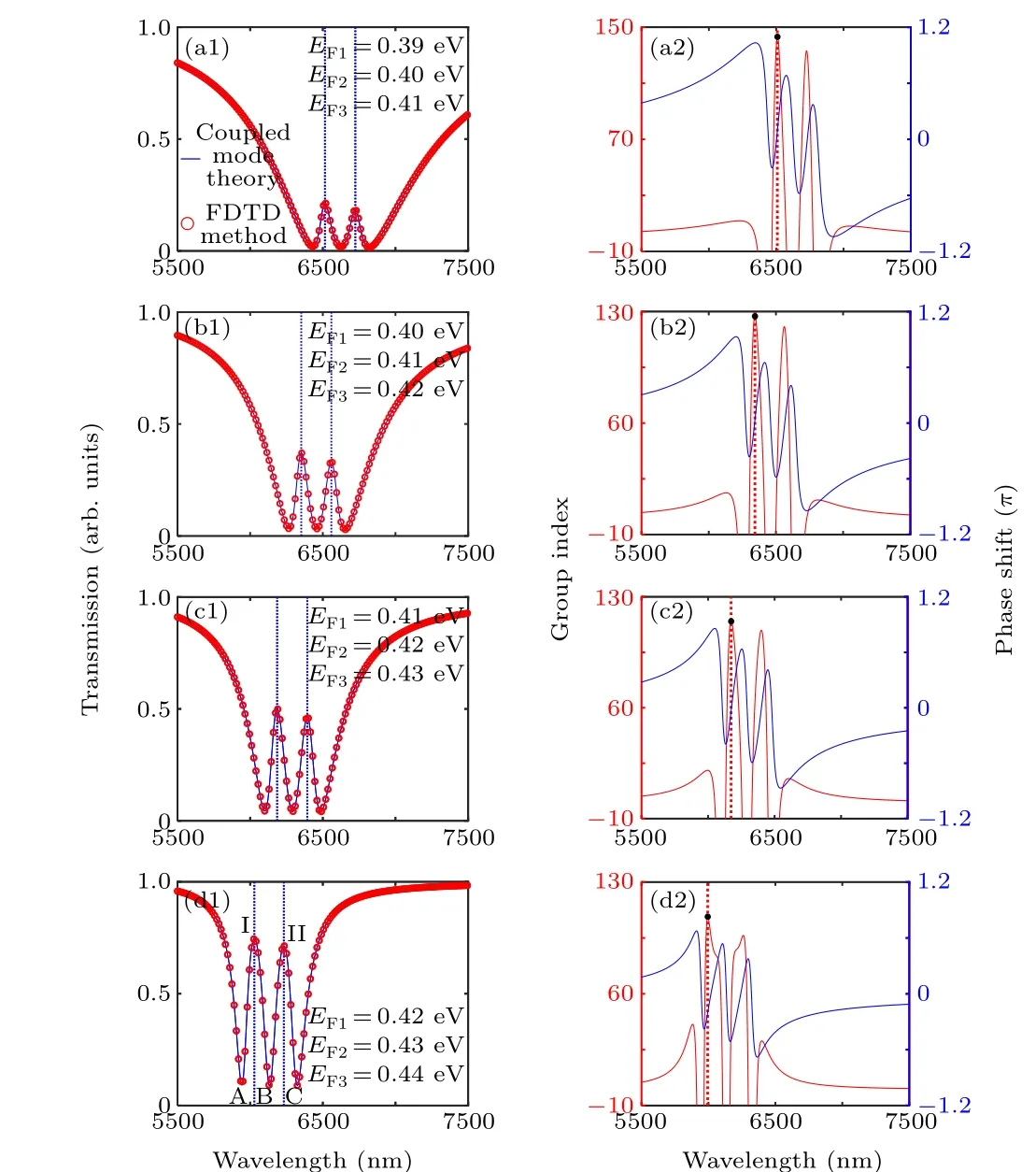
Fig. 10. Dual-PIT effect simulation analysis of triple cavities side-coupled with a graphene nanoribbon waveguide system. (a1)–(d1) Transmission spectra of the dual-PIT effect. (a2)–(d2) Corresponding transmission phase shift responses and group indexes.
Figures 10(a1)–10(d1)show the normalized transmission intensity spectra of the dual-PIT effect under various Fermi levels of graphene rectangle cavities. The resonant wavelengths of cavities 1, 2, and 3 show a blue shift, and the two PIT transmission peaks increase with the Fermi levels of graphene rectangle cavities,as shown in Figs.10(a1)–10(d1).The transmission peaks I and II of the dual-PIT effect are the minimum values of only 21%and 18%,respectively,when the Fermi levels of graphene rectangle cavities 1,2,and 3 are 0.39,0.40,and 0.41 eV,respectively,as shown in Fig.10(a1). However, the values of the transmission peaks I and II can reach 74%and 71%,respectively,when the Fermi levels of graphene rectangle cavities 1, 2, and 3 are 0.42, 0.43, and 0.44 eV, respectively,as shown in Fig.10(d1). These results indicate that the dual-PIT effect can be effectively tuned by adjusting the Fermi level of the graphene rectangle cavity.
Figures 10(a2)–10(d2) show the transmission spectrum phase shifts and group indexes of dual-PIT effect with the change in the Fermi level of graphene rectangle cavity. The results reveal the aggressive phase changes of the dual-PIT windows. The strong destructive interference near the peak of the transparency in the monolayer graphene-PIT structure results in a drastic dispersion. Hence, this phenomenon can induce a phase mutation, and the round-trip phase difference between the two cavities in the PIT system is an integer multiple of 2π. The transmission phase shifts of the dual-PIT effect caused by the light resonance in cavities 1 and 2 as well as cavities 2 and 3 are 0π. The dispersions are normal in the three cavity systems. Then,the phase dispersion results in a change in the group index. The group index of the dual-PIT system increases with the decrease in the Fermi level of the graphene rectangle cavity, and the two transmission peaks decrease, as shown in Figs. 10(a2)–10(d2). This trend is due to the additional time spent by the signal light in resonance between cavities 1 and 2 as well as that between cavities 2 and 3,resulting in increased optical power loss among the three rectangle cavities. Therefore, the output light intensity of the dual-PIT system decreases with the graphene Fermi level. Moreover,a large group index is always maintained at the peak wavelength of the dual-PIT system. The corresponding maximum group indexes are 143.2, 127.3, 116.2, and 108.6, as shown in the black dots of Figs. 10(a2)–10(d2). These results can be applied to dynamically tunable two-channel optical filters,optical modulators,[44]and slow light devices because of high transmission and ultranarrow bandwidth.[12]
The field distributions of|Hz|2at the two peak wavelengths are depicted by simulation at the transmission peak wavelengths, as shown in Figs. 11(a) and 11(b) to further understand the dual-PIT effect mechanism of this structure.Herein, the Fermi levels of rectangle cavities 1, 2, and 3 are 0.42, 0.43, and 0.44 eV, respectively. Figure 11(a) shows the magnetic field distribution at the peak wavelength ofλ12=6232 nm when the light is resonated between cavities 1 and 2.Moreover,figure 11(b)shows the magnetic field distribution at the peak wavelength ofλ23=6029 nm when the light is resonated between cavities 2 and 3. The corresponding transmission spectrum of the dual-PIT effect is shown in Fig. 10(d1).The results indicate that the three rectangle cavities act as three resonators,and the Fabry–Perot resonance is realized between cavities 1 and 2 or cavities 2 and 3. Therefore, the formation mechanism of the dual PIT effect is the same as that of the single PIT effect, which is caused by resonance between two rectangle cavities.

Fig.11. |Hz|2 magnetic field distributions of the dual-PIT effect in triple cavities side-coupled with a graphene nanoribbon waveguide system at the peak wavelength.
6. Simulation results and discussion of triple-PIT system
Figure 1(d) shows that the triple PIT system comprises rectangle cavities 1, 2, 3, 4, and the graphene nanoribbon waveguide. The triple-PIT effect is also obtained by the combination of a bright and dark mode coupling and the cavities side-coupled with a graphene nanoribbon waveguide mechanism. The Fermi levels of graphene rectangle cavities 1,2,3,and 4 are initially set to 0.40,0.42,0.42,and 0.44 eV,respectively. The dynamic transmission characteristics for the triple-PIT system in Figure 12 are analyzed by a temporal CMT.The normalized amplitudeaifor the time-harmonic field e−jωtof thei-th cavity(i=1,2,3,4)are given by the following equations
whereω01is the intrinsic resonant frequency of cavities 1 and 2, andω02is the intrinsic resonant frequency of cavities 3 and 4.κw,i(i=1, 3) is the attenuation ratio due to energy coupling into the graphene nanoribbon waveguide, andκint,i(i=1,2,3,4)is the attenuation ratio of thei-th rectangle cavity.µ12=ω01/(2Qc,1)andµ34=ω02/(2Qc,2)are the coupling coefficients between cavities 1 and 2 and between cavities 3 and 4, respectively.Qw,i(i=1, 3),Qint,i(i=1, 2, 3, 4), andQc,i(i=1,2)are the waveguide coupling loss,cavity quality factors due to the intrinsic loss, and direct coupling between bright and dark modes,respectively.

Fig. 12. Schematic diagram of the realizing principle of the triple-PIT system.
The energy conservation of the output wave amplitude in each cavity indicates that the output spectral transmittance of the system for the triple-PIT system is as follows:

whereβ1=j(ω −ω01)+κint,1,β2=j(ω −ω01)+κint,2,β3=j(ω −ω02)+κint,3,β4= j(ω −ω02)+κint,4, andtdare the transmission coefficients of the triple-PIT system.
The total quality factors are caused by the triple-PIT transparent peaks. The corresponding intrinsic quality factors,total quality factors,and the coupling quality factors of rectangle cavities 1 and 3 are shown in Table 3.Herein,Qc,1=42.13,41.85,41.27,40.93,andQc,2=41.43,41.12,40.87,40.46.
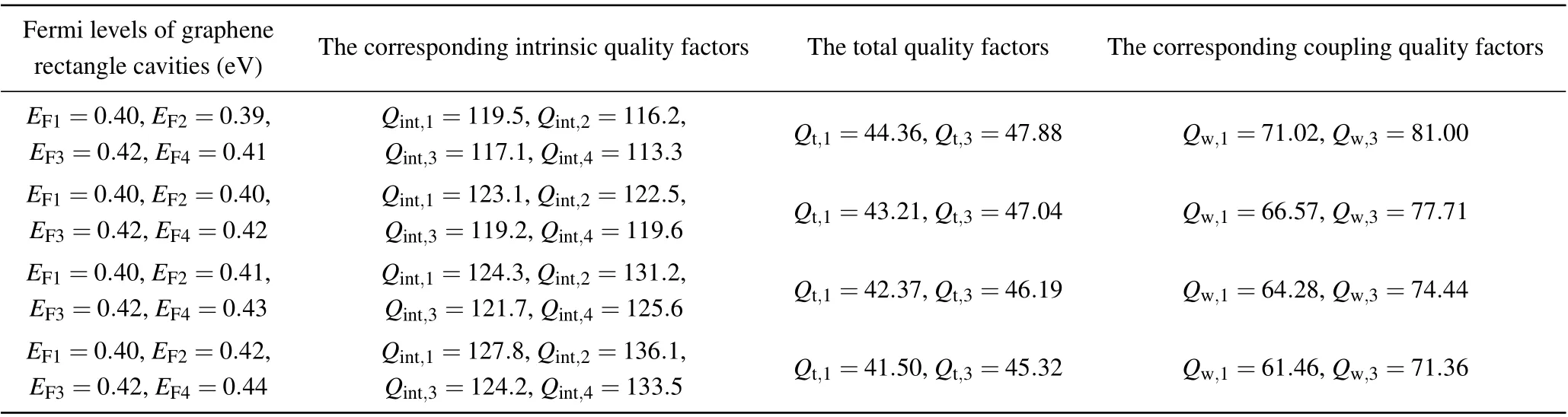
Table 3. Qint,Qt,and Qw under different Fermi levels of graphene rectangle cavities triple-PIT system.


Fig.13. Triple-PIT effect simulation analysis. (a1)–(d1)Transmission spectra of the triple-PIT effect. (a2)–(d2) Corresponding phase-shift responses and group indexes.
Figures 13(a1)–13(d1)show the normalized transmission intensity spectra of triple-PIT effect under various Fermi levels of graphene rectangle cavities. The peak wavelengths show a blue shift,and the triple-PIT transmission peaks increase with the Fermi levels of graphene rectangle cavities, as shown in Figs. 13(a1)–13(d1). Figure 13(a1) shows that the transmission peaks I,II,and III of the triple-PIT effect are the minimum values of 51%, 44%, and 51%, respectively, when the Fermi levels of graphene rectangle cavities 1, 2, 3, and 4 are 0.40,0.39,0.42,and 0.41 eV,respectively Meanwhile,the values of the transmission peaks I,II,and III can reach 74%,65%,and 73%,respectively. These results are attributed to the strengthened coupling strength,which is affected by the resonance between the bright and dark modes and the resonance between rectangle cavities and a graphene nanoribbon waveguide when the Fermi levels of graphene rectangle cavities 1, 2, 3, and 4 are 0.40, 0.42, 0.42, and 0.44 eV, respectively, as shown in Fig.13(d1). Therefore,the triple-PIT effect can be effectively tuned by adjusting the Fermi level of the graphene rectangle cavity.
Figures 13(a2)–13(d2) show the transmission spectrum phase shifts and group indexes of triple-PIT effect with the change in the Fermi level of graphene rectangle cavity. The group index sharply drops due to the sudden change in the phase shift at the transmission dip. A 2πphase shift exists at the peak wavelength, and the highest group index reaches 161.4. Hence, a large group index is obtained near the transmission dip due to the strong dispersion. The corresponding frequency light signal remains longer than other frequencies when it travels in this structure.This feature enables the device to be used in optical storage applications. If the Fermi level of the dark mode of cavities 2 and 4 is tuned to differ from the bright mode of cavities 1 and 3 by varying applied voltage attached to graphene,then the group index increases,and the corresponding maximum group indexes are 161.4, 144.8,131.4,and 115.8,as shown in the black dots of Figs.13(a2)–13(d2). Thus, the triple-PIT phenomenon can be effectively modulated to seek the desired slow light effect. These results can be applied to dynamically tunable three-channel optical filters,[6]optical modulators,[44]sensors,[45]switching,[46,47]and slow light devices[11]with high transmission,ultranarrow bandwidth,and good slow light effect.
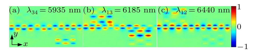
Fig.14. |Hz|2 magnetic field distributions of the triple-PIT effect at the peak wavelength.
Figures 14(a)–14(c) show the field distributions of|Hz|2at the three peak wavelengths represented by I, II, and III by using the FDTD method in Fig. 13(d1) to further understand the triple-PIT effect mechanism of this structure.The field distributions of|Hz|2shown in Figs.14(a)and 14(c)demonstrate that the strongly destructive interference between the bright and dark cavities produced the transmission peaks I and III,thereby enabling the propagation of the SPP wave through the structure without limitation. Notably, the dark cavity is activated strongly, and the magnetic field of the bright cavity is activated weakly at 5935 nm and 6440 nm. Therefore,the drastic excitation of the dark cavity can destructively restrain the oscillation of the bright cavity. Moreover,the occurrence of the transmission peak II at 6185 nm is very different from that of peaks I and III because all bright cavities are activated simultaneously,as shown in Fig.14(b). Meanwhile,the bright-dark mode and waveguide couplings between the cavities below and above the graphene nanoribbon waveguide affect the transmission spectrum simultaneously. The formation of transmission peak II is due to the destructive interference between the magnetic fields of cavities below and above the graphene nanoribbon waveguide.
Table 4 shows the maximum transmission and group index of the dual and triple-PIT systems under different Fermi levels of graphene rectangle cavities and pump light intensity at the peak wavelength of PIT. The transmission peak of the dual-PIT effect is tuned from 21%to 74%and the group index of the dual PIT system is controlled between 143.2 and 108.6 when the Fermi levels of graphene rectangle cavities 1,2,and 3 are 0.39 eV to 0.42 eV, 0.40 eV to 0.43 eV, and 0.41 eV to 0.44 eV, respectively. This finding indicates that dual PIT systems always maintain a large group index and good slow light effect. Furthermore, the transmission peak of the triple-PIT effect is tuned from 51%to 74%,and the group index of the triple-PIT system is controlled between 161.4 and 115.8 when the Fermi levels of graphene rectangle cavities 2 and 4 are 0.39 eV to 0.42 eV and 0.41 eV to 0.44 eV, respectively.Thus,the maximum group index is realized,and the best slow light effect can be obtained in the triple-PIT system. Meanwhile, as the intensity of the PIT transparent peak decreases at all PIT windows, the group index increases. The reason is that as the signal light takes more time to resonate in rectangle cavities,more light power is lost by scattering in the cavities.Therefore,the group index is enhanced at all PIT windows.
The resonant wavelengths of the three cavities are blueshifted at the same time,the bandwidth is almost constant and the transmission spectrum changes more obviously with the increase of the Fermi levels of the three rectangle cavities,which is different from the bandwidth widening in the two cavities side-coupled with a graphene nanoribbon waveguide system. According to

the group index increases. It is worth noting that the transmission phase shift in the triple PIT windows violently changes.In this ultracompact structure, the strong destructive interference near the transparent peak results in a more severe dispersion and a stronger coupling between the rectangle cavities.A mutation of the transmission phase shift can be obtained in this work. Hence,the stronger dispersion and coupling lead to the increase of the group index.
In addition,Hanet al.proposed that the multiband PIT effect is dynamically tuned by a pump light.[26]The maximum transmission of the PIT effect is 58% when the intensity of the pump light is 5 MW·cm−2,and the group index can reach 6. Dynamically tunable slow light effect is obtained using the pump light. However,a considerably large group index can be obtained,and an effective slow light effect can be achieved in the PIT system investigated in this study.
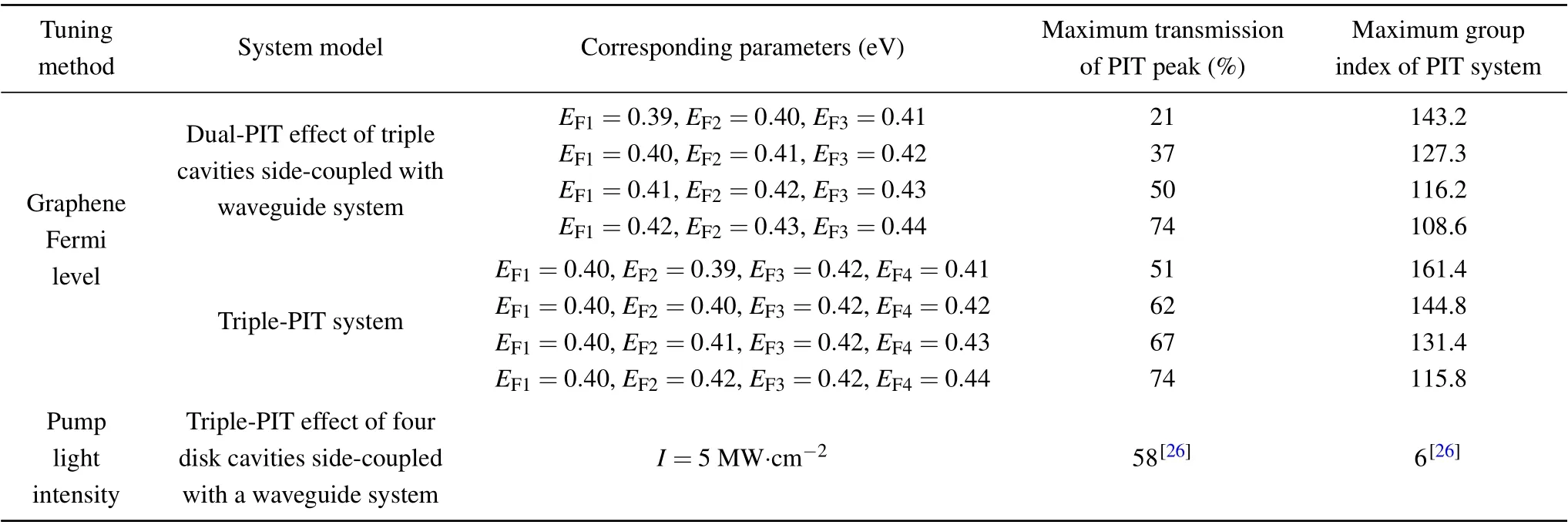
Table 4. Maximum transmission and group index of the dual-and triple-PIT systems under different Fermi levels of graphene rectangle cavities and pump light intensity at the peak wavelength of PIT.
7. Conclusion
In summary, dynamic tunable multiband PIT effects are theoretically and numerically studied on the basis of considerable rectangle cavities coupled with a plasmon waveguide system by tuning the Fermi level of the graphene rectangle cavity. Two completely different realization methods are used to achieve single-PIT effect: one is the bright and dark mode coupling through direct destructive interference,and the other is the cavity coupled with a graphene nanoribbon waveguide through indirect destructive interference.In addition,dual-PIT effect is obtained by three rectangle cavities side-coupled with a graphene nanoribbon waveguide. The transmission of the dual-PIT effect can be significantly tuned between 0.21 and 0.74,and the corresponding group index is controlled between 143.2 and 108.6. This finding indicates that a large group index is maintained and a good slow light effect is realized in the dual-PIT system. Furthermore, the triple-PIT effect is achieved by combining bright–dark mode coupling and the cavities side-coupled with a graphene nanoribbon waveguide mechanism. The results reveal that considerably sharp transparent windows of triple-PIT effect can be obtained, a high transmission is maintained between 0.51 and 0.74,and the corresponding group index is controlled between 161.4 and 115.8.Therefore,the maximum group index is realized,and the high transmission and the best slow light effect can be obtained in the triple-PIT system.The proposed structure is ultra-compact because its size is less than 0.5 µm2and considerably easier to fabricate than the proposed graphene-based metamaterial structures. Moreover,the slow light effect is more significant than the metal waveguide coupled structure. Therefore, the current study not only introduces a novel approach toward the realization of optical sensors and optical filters, but also has important application in slow light and light storage devices with ultrafast,ultracompact,multiband,and dynamic tunable.
Acknowledgments
Project supported by the National Natural Science Foundation of China (Grant Nos. 11647122 and 61705064), the Natural Science Foundation of Hubei Province,China(Grant Nos. 2018CFB672 and 2021CFB607), the Project of the Hubei Provincial Department of Education, China (Grant Nos.B2021215 and T201617),and the Natural Science Foundation of Xiaogan City,China(Grant Nos.XGKJ2021010002 and XGKJ2021010003).
猜你喜欢
杂志排行

Chinese Physics B的其它文章
- Direct measurement of two-qubit phononic entangled states via optomechanical interactions
- Inertial focusing and rotating characteristics of elliptical and rectangular particle pairs in channel flow
- Achieving ultracold Bose–Fermi mixture of 87Rb and 40K with dual dark magnetic-optical-trap
- New experimental measurement of natSe(n,γ)cross section between 1 eV to 1 keV at the CSNS Back-n facility
- Oscillation properties of matter–wave bright solitons in harmonic potentials
- Synchronously scrambled diffuse image encryption method based on a new cosine chaotic map