Spatial and spectral filtering of tapered lasers by using tapered distributed Bragg reflector grating
2022-08-31JingJingYang杨晶晶JieFan范杰YongGangZou邹永刚HaiZhuWang王海珠andXiaoHuiMa马晓辉
Jing-Jing Yang(杨晶晶), Jie Fan(范杰), Yong-Gang Zou(邹永刚),Hai-Zhu Wang(王海珠), and Xiao-Hui Ma(马晓辉)
State Key Laboratory of High Power Semiconductor Laser,Changchun University of Science and Technology,Changchun 130022,China
Keywords: tapered lasers,distributed Bragg reflector,backward-traveling wave,parasitic oscillation
1. Introduction
High-brightness tapered lasers with narrowband emission are required for many applications, such as solid state and fiber lasers pump, nonlinear frequency conversion and freespace communication.[1,2]Such lasers use a ridge waveguide(RW) to provide a lateral single-mode emission and amplify the output power without degrading the beam quality by a tapered amplifier(TA).Meanwhile,the distributed Bragg reflector (DBR)[3–5]or distributed feedback (DFB)[6–8]grating is used to narrow the spectral linewidth. However, because the width of the front facet is much larger than that of the RW,the side backward-traveling waves is formed due to the residual reflection of the TA section, which leads to the parasitic oscillation adjacent to the RW section and destroys the performance of the laser.[9,10]
Several studies have been carried out to suppress this parasitic oscillation and improve the performance of tapered lasers, such as the low reflectivity facet,[11,12]beam spoilers,[13,14]bent amplifier structure,[15–17]etc. Helalet al.[12]studied the mechanism of beam quality degradation of tapered laser at high operating power. They pointed out that the backward traveling wave is one of the main reasons for beam quality deterioration,and the beam quality could be increased effectively by reducing the facet reflectivity. Borruelet al.[14]eliminated the backwards optical field on both sides of RW by introducing the beam spoilers, and improved the maximum output power and beam quality of the tapered laser.Micka¨el Faugeronet al.[16]developed a 1550 nm bent master oscillator power amplifier(MOPA),which includes a DFB laser,a modulation section and a flared semiconductor optical amplifier (SOA) section. The bent architecture of the device reduced the facet reflections to the DFB laser,thus obtained a stable wavelength emission without mode hopping. In recent years,Andr´e M¨ulleret al.[18]showed that the tapered layout of DBR grating can improve the diffraction efficiency of grating and increase the central lobe output power of tapered laser.
In this paper,we have designed and fabricated a 3.5 mm long 1040 nm tapered laser with a tapered DBR grating (TDBR). Based on the scattering effect of T-DBR on the side backward-traveling wave,T-DBR exhibits additional suppression effect on parasitic oscillations while maintaining the linewidth narrowing effect, and thus further improving the spatial and spectral characteristics of the tapered laser. The side lobes in the lateral far field of the tapered laser are eliminated and a single-lobe profile is obtained. Meanwhile, the tapered laser eliminates the multi-mode operation in the spectral characteristics,and obtains the single peak emission with a linewidth of 56 pm.
2. Device design and fabrication
The schematic of a tapered laser with T-DBR is shown in Fig.1(a). The device is designed to be 3.5 mm in length,consisting of a 1 mm long T-DBR section,a 1 mm long RW section and a 1.5 mm long TA section. The T-DBR has a grating period of 960 nm and a taper angle of 4◦, providing narrow linewidth feedback while filtering parasitic oscillation. The width of RW section is 5 µm to achieve single lateral mode emission. The TA section has an output aperture of 138µm in the lateral direction,corresponding to a taper angle of 5◦.
The epitaxy structure of the 1040 nm tapered laser is shown in Fig. 1(b), and it is grown by metal-organic chemical vapor deposition (MOCVD). An InGaAs/GaAs single quantum well active region is embedded in a symmetric Al0.3Ga0.7As large optical cavity. The optical confinement layers are sandwiched between two Al0.5Ga0.5As cladding,and the top contact layer is highly doped p-GaAs.
The sixth order T-DBR is fabricated by electron-beam lithography and inductively coupled plasma(ICP)etching,as shown in Fig. 1(c). Figure 1(d) shows a cross-sectional view of the grating after etching, revealing a consistent residual layer thickness and uniform grating grooves. The RW section and TA section with different depth are fabricated by multiple UV lithography technology. A 300 nm thick SiO2layer is deposited by plasma enhanced chemical vapor deposition(PECVD)as an electrical insulation layer. The P-ohmic contact metal of Ti/Pt/Au is deposited on the top of the RW and TA sections. The separation contact is prepared by removing the metal between the RW section and TA section with lift-off technology. After substrate thinning and polishing, a Ni/AuGe/Ni/Au N-contact metal is deposited on the back of the GaAs substrate. For the purpose of accurate comparison,the device with straight DBR grating (S-DBR) is also fabricated. Both facets of the devices are uncoated. Finally, the tapered lasers are mounted p-side up on a CuW heat spreader for test,as shown in Fig.1(e).
The parameters of the T-DBR are carefully designed to realize the narrow linewidth emission of the laser. Because the even-order gratings have a local minimum of reflectivity at duty cycle of 0.5,[19]the duty cycle of 0.4 is chosen for easy fabrication.The reflection spectrum of a 1-mm long DBR with a sixth-order surface grating are calculated with the commercial simulator Rsoft. Figure 2(a)shows the contour plot of the amplitude reflection versus different periods, with an interval of 5 nm for varied period from 940 nm to 970 nm. It can be seen that with the increase of the period, the peak reflection wavelength of the grating gradually moves to the long wave direction. And a peak reflectivity wavelength of 1048 nm is obtained at the period of 960 nm,which is shown in Fig.2(b).
In order to clarify the working mechanism of T-DBR suppressing side backward-traveling waves, the structure of TDBR is modeled in detail by finite-difference time-domain(FDTD) software, and the influence of T-DBR with different taper angles on the transmission characteristics of side backward-traveling waves is studied. In the simulation, the length of T-DBR is 100µm,and the width of the light incident surface is 5µm. The light sources of side backward-traveling waves are located on both sides of the grating. Figure 3(a)shows the modal field distributionE(x,y) of side backwardtraveling waves after passing the S-DBR (taper angle = 0◦).It can be seen that most of side backward-traveling waves can transmit to the rear facet of the tapered laser via both sides of the S-DBR, resulting in parasitic oscillation. Therefore, the beam spoilers are usually introduced on both sides of the RW to suppress parasitic oscillation.[13,14]With the increase of the taper angle of the grating, the scattering effect of the grating on the side backward-traveling wave increases gradually, as shown in Figs.3(b)–3(d). This indicates that the T-DBR will increase the loss of side backward-traveling waves transmitted to the rear facet of the laser, thus suppresses the parasitic oscillation of the tapered laser. This also indicates that for the tapered laser with T-DBR,no additional fabrication process is required to fabricate the filter structure to suppress parasitic oscillation.
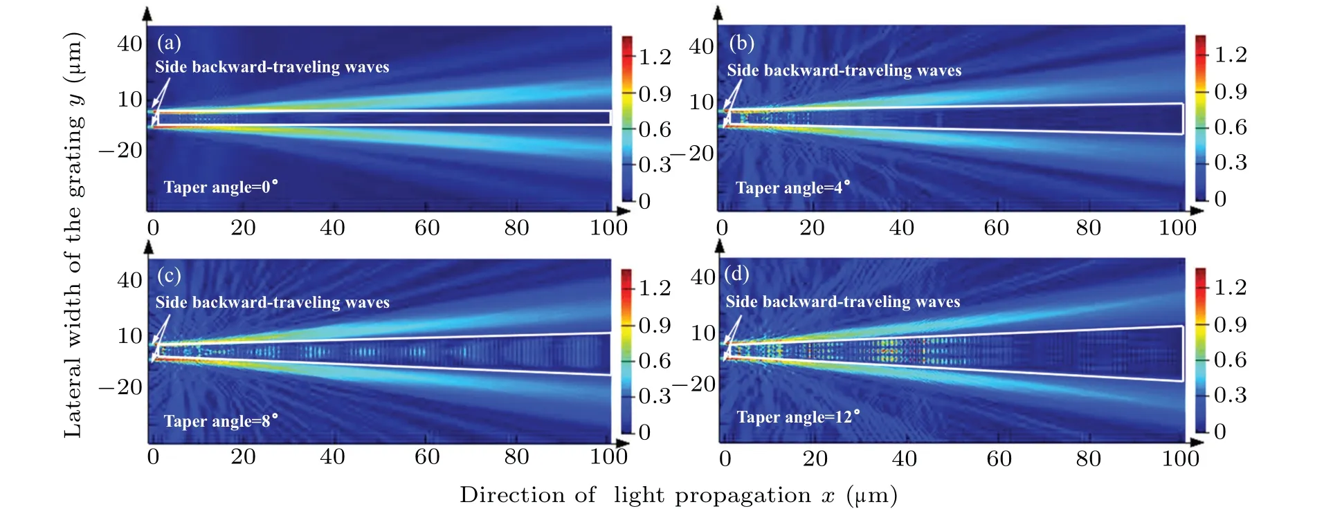
Fig. 3. The influence of taper angle of grating on the modal field distribution E(x,y) of backward-traveling wave; (a) taper angle = 0◦; (b)taper angle= 4◦;(c)taper angle= 8◦;(d)taper angle= 12◦.

Fig. 4. Influence of T-DBR with different structure parameters on the transmission characteristics of side backward-traveling waves: (a) reflection;(b)transmission;(c)loss.
Figures 4(a)–4(c)show the influence of length and taper angle of T-DBR on the transmission,reflection and loss of side backward-traveling waves. With the increase of T-DBR taper angle,the reflection increases slightly and the transmission decreases,which is caused by the widening of T-DBR width.[20]At the same time, with the increase of T-DBR taper angle,more side backward-traveling waves will be scattered into the non-gain region of the laser, resulting in the increase of the loss of side backward-traveling waves. Although the slight increase of the reflection of side backward-traveling waves will promote the parasitic oscillation of the laser,the increased loss and the reduced transmittance will more significantly reduce the side backward-traveling waves reflected from the rear facet, and this is helpful to suppress the parasitic oscillation.In addition,with the length increasing from 50µm to 100µm,the T-DBR obtains similar reflection, higher loss and lower transmission. This indicates that the suppression effect of parasitic oscillation can be enhanced by lengthening the T-DBR.For the T-DBR with 4◦taper angle and 100µm length,the reflectivity is increased by 5%,the transmittance is decreased by 14%and the loss is increased by 9%in comparison with those of S-DBR.
3. Results and analysis
A B262 CCD camera with a resolution of 12 M@16.5 fps/4 K@30 fps is used to measure the far-field spot of the tapered laser. Figure 5 shows the measurement results of the far-field distribution of the tapered lasers. The measurement results are obtained under the condition that the output power is 60 mW and the distance from the front facet is 1 cm. It can be seen that the far-field distribution of S-DBR tapered laser presents multiple lobes in the lateral direction.This is mainly due to the lack of the suppression structure of the side backward-traveling waves, and the parasitic oscillation in the tapered laser can not be effectively suppressed.[21]Due to the scattering effect of T-DBR on side backward-traveling waves, the lateral side lobes in the far-field distribution of tapered laser are eliminated. Therefore, the T-DBR tapered laser presents a single-lobe profiles with near-Gaussian distribution. The measured far-field spots of the laser at different TA current are shown in the inset of Fig. 5. The spot shape of S-DBR tapered laser shows obvious multi-lobe distribution under all tested current conditions. Compared with S-DBR tapered laser,the spot shape of T-DBR tapered laser is obviously improved, which is a single-lobe distribution. This indicates that T-DBR has a significant spatial filtering effect on the side backward-traveling waves.
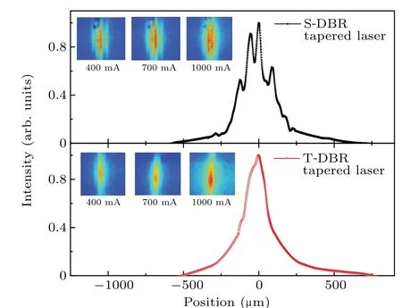
Fig.5. Lateral far-field distribution of tapered lasers at the same output power. The inset shows the far-field spots of the laser at different TA current.
The spectral behavior of the tapered lasers is recorded with a YOKOGAWA AQ6370D spectrometer having a resolution of 0.02 nm. Figure 6 shows the emission spectra of the tapered lasers with different TA currents(ITA)at 200 mA RW current (IRW). All the emission spectra are measured at heat sink temperature of 20◦C. Each spectrum is individually normalized in intensity to 1. It can be seen that the emission spectrum of S-DBR tapered laser has several small side peaks in addition to the main peak atITA=700 mA. When theITAincreases to 1000 mA, the S-DBR tapered laser exhibits multi-mode emission, and the side mode suppression ratio decreases sharply. The multi-mode emission behavior of S-DBR tapered laser result from the compound cavity effects which are caused by the parasitic oscillations.[22]These effects produce self-pulsations and coupled-cavity mode competition,resulting in the modal instabilities,such as mode hopping and multi-mode operation.[22–24]In comparison with that of S-DBR tapered laser,the T-DBR tapered laser shows an excellent spectral filtering effect. Due to the suppression effect of T-DBR on parasitic oscillation, the spectral characteristics of T-DBR tapered laser are effectively improved,and a stable single peak emission is obtained in the range of test current.Finally, for the T-DBR tapered laser, a single peak emission with wavelength of 1046.84 nm and linewidth of 56 pm is obtained atIRW=200 mA andITA=1000 mA,as shown in the inset in Fig.6.

Fig.6. Normalized emission spectra tapered lasers with different ITA at IRW=200 mA.The inset shows the linewidth at ITA=1000 mA.
A THORLABS S146C integrating sphere power sensor head with InGaAs detector is used to measure the output power of the tapered laser. The resolution of the detector is 10 nW.The power–current–voltage(P–I–V)characteristics of the devices at heat sink temperature of 20◦C are shown in Fig. 7. The results show that S-DBR tapered laser and TDBR tapered laser have almost the sameI–Vcharacteristics.The kinks ofP–Icharacteristics related to mode hopping and multi-mode operation can be clearly seen in S-DBR tapered laser. For the T-DBR tapered laser,the kinks caused by mode hopping and multi-mode operation are eliminated,and a kinkfreeP–Icharacteristic is obtained. Although the output power of the T-DBR tapered laser is reduced due to the suppression of side backward-traveling waves,the high output power can further been achieved by evaporating anti-reflective coating and increasing the the length ratio of TA section to RW section.[25]

Fig.7. The P–I–V characteristics of the tapered lasers.
4. Conclusion
In conclusion,a 1040 nm tapered laser with T-DBR structure is fabricated. By scattering the side backward-traveling waves,the T-DBR effectively suppresses the parasitic oscillation of the tapered laser,and maintains the effect of linewidth narrowing. Due to the suppression of parasitic oscillation by T-DBR, the spatial and spectral characteristics of the tapered laser are improved.The experimental results show that the lateral side lobes in the far-field distribution are eliminated and a single-lob profile is realized. The multi-mode operation of the spectrum is suppressed, and a single peak emission with wavelength of 1046.84 nm and linewidth of 56 pm is obtained.Meanwhile,a kink-freeP–Icharacteristic is obtained by eliminating mode hopping and multi-mode operation. In addition,since no additional filter structure is required,the manufacturing process of T-DBR tapered laser can be simplified.
Acknowledgement
Project supported by Jilin Science and Technology Development Plan, China (Grant Nos. 20210201030GX and 20190302052GX).
猜你喜欢
杂志排行

Chinese Physics B的其它文章
- Direct measurement of two-qubit phononic entangled states via optomechanical interactions
- Inertial focusing and rotating characteristics of elliptical and rectangular particle pairs in channel flow
- Achieving ultracold Bose–Fermi mixture of 87Rb and 40K with dual dark magnetic-optical-trap
- New experimental measurement of natSe(n,γ)cross section between 1 eV to 1 keV at the CSNS Back-n facility
- Oscillation properties of matter–wave bright solitons in harmonic potentials
- Synchronously scrambled diffuse image encryption method based on a new cosine chaotic map