Design of three-dimensional imaging lidar optical system for large field of view scanning
2022-08-01QingYanLi李青岩YuZhang张雨ShiYuYan闫诗雨BinZhang张斌andChunHuiWang王春晖
Qing-Yan Li(李青岩), Yu Zhang(张雨), Shi-Yu Yan(闫诗雨),Bin Zhang(张斌), and Chun-Hui Wang(王春晖),†
1National Key Laboratory of Tunable Laser Technology,Harbin Institute of Technology,Harbin 150001,China
2Geling Institute of Artificial Intelligence and Robotics,Shenzhen 518063,China
Keywords: 3D lidar,MEMS scanning system,large field of view scanning,Zemax
1. Introduction
With the rapid development of artificial intelligence, internet,automation and sensors,three-dimensional(3D)imaging laser radar has been widely used in many fields, such as topographic mapping,[1]atmospheric detection,[2,3]environmental sensing,[4,5]target detection[6]and automatic driving,[7]due to its high measurement accuracy, good directionality, fast speed and less affected from the ground clutter.[8,9]At present, the mainstream 3D imaging lidar solutions include mechanical rotary lidar, micro-electromechanical system(MEMS)scanning lidar,optical phased array(OPA)and flash lidar. The mechanical rotary laser 3D image sensor[10,11]was developed earliest and is the most mature technology. However, due to the limitation of the technical system, it is bulky and needs to be installed externally on the roof. In addition,its cost has become the main constraint.
Compared with the mechanical lidar, solid-state lidar eliminates the mechanical structure of complex highfrequency rotation,greatly improves durability,and greatly reduces the volume. Pure solid-state lidar mainly includes OPA and flash lidar.Flash lidar[12,13]emits a large area of laser light to cover the detection area directly in a short period of time,and the image of the surrounding environment can be drawn through a highly sensitive receiver.Flash lidar has no scanning device,fast imaging speed,high integration,small size,chiplevel technology,suitable for mass production,and can further reduce costs and ensure the service life of the device. However,the flash lidar requires a high-power laser source,which can be dangerous to humans and animals. In addition,the detection distance is close, which is the crucial factor restricting its development. OPA scanning technology is an entirely solid-state technology. OPA lidar[14,15]uses pure solid-state devices without any mechanical removable structures and performs better in terms of durability.However,OPA lidar is easy to form side lobes,which damages the beam range and angular resolution, and requires the size of the array unit to be no more than half a wavelength. The requirements for materials and processes are extremely demanding, so the cost is correspondingly high.
MEMS lidar[16,17]is a compromise between the mechanical and solid-state lidar, and it still has mechanical rotating parts. MEMS micromirrors have the characteristics of small size, light weight, fast scanning speed, low power consumption, relatively low price, and insensitivity to environmental impact. This makes it possible for lidar to achieve miniaturization, high frame rate, high accuracy and high precision measurement. Therefore, the MEMS scanning micromirror has become one of the extremely important components in the optical scanning system. Compared with other schemes,MEMS lidar integrates many advantages of other schemes.The future technological development must be towards solidstate and miniaturization, but because the current solid-state solution is not yet mature and the hardware cost is relatively high,it cannot be commercialized on a large scale. The hybrid solid-state lidar has better performance than the mechanical type, and the technology is more mature than the solid-state lidar. Therefore, it is the currently most feasible solution for large-scale practical applications. While the MEMS lidar is commercially available on a large scale,the technical solution must overcome the shortcomings of the small scanning angle of the MEMS scanning mirror.[18]
In order to solve the shortcomings of the MEMS micromirrors,some solutions have been proposed. For example,Cristiano Niclasset al.[19]proposed to use three laser diodes to form a linear array that could converge the outgoing laser beam through a large positive lens to the MEMS mirror, ultimately achieving the expansion of the scanning field of view.But this method requires multiple lasers. Other researchers have also proposed a method of realizing the expansion of angle by using positive and negative lens groups.[20]With a positive lens and a negative lens placed in the front and back of the MEMS micromirror, respectively, a Galileo telescope is formed, which can increase the scanning field of view effectively.Although such a structure is simple and can help expand the field of view, the beam divergence angle is also enlarged,which would make the target spot very large and weak the echo signals when performing long-distance detections. Besides,the range of angle expansion is not enough.This method is only suitable for systems with excellent beam collimation.Another method is to use a fisheye lens[21]or a wide-angle lens,[22]but the imaging surface is distorted severely.
In order to overcome these shortcomings and realize the field of view expansion and collimation of beam scanning,a new MEMS micromirror folding scanning emission optical system design is proposed. This article aims to design a scanning emission system with a scanning field of view greater than 40°,a divergence angle of less than 2 mrad,and a spot diameter of less than 40 cm at a detection distance of 100 m.The MEMS micromirror used in this system is the model S4342 product from American Mirrorcle company. Its mechanical rotation angle is±5°. Through the theoretical derivation of the relationship among the probe beam divergence angles,the scanning field of view and the parameters of the optical system components, the structure and parameters of the system are determined,and the compensation lens group is introduced to achieve the final parallel beam scanning. The system is designed and optimized by Zemax software. The final design results show that the designed system scan field reaches 53°×53°. The spot diagram at a distance of 100 mm from the exit surface shows that the maximum radius of the spot is 0.506 mm.The maximum radius of the spot at 100 m is 19 cm,and the diffusion angle is less than 2 mrad.
2. The theoretical basis and model of the system
2.1. Pulsed lidar system and its operating principle
The laser 3D image sensor system is mainly composed of three parts: a transmitting system, a receiving system,and a signal processing system.[23–25]The transmitting system consists of a pulsed fiber laser,a scanning optical system,and an excellent MEMS scanning mirror. The receiving system includes a large field-of-view focusing lens and a highspeed photodetector time interval measurement system(timeto-digital converter TDC). The signal processing system sets the relevant parameters,sends out the synchronization signal,processes the 3D data points set,and then transmits the image to the display. Figure 1 shows the schematic diagram of the lidar system.
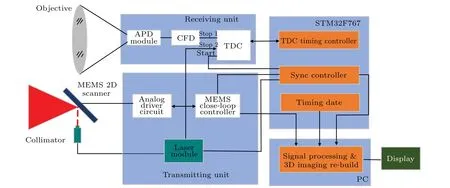
Fig.1. The schematic diagram of the lidar system.
In a lidar system,the laser source is very important. The laser beam emitted by the system must be stable, and the divergence angle must be controlled within a certain range. A 1550 nm wavelength optical fiber laser is used as the transmitting module and the output laser repetition frequency can be adjusted.Here it is temporarily set to be 250 kHz and the pulse width is 4 ns. The mechanical rotation angle of the MEMS scanning mirror is±5°,and the effective reflection surface diameter is 2000 μm. The laser beam is detected by using the beam quality analyzer PY-III-CA of Ophir-Spiricon Inc. As shown in Fig.2,the beam quality of the laser is good,the output spot diameter is 3 mm,and there is a divergence angle of 5 mrad.
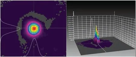
Fig.2. Tested laser beam quality.
2.2. Theoretical derivation
In 3D imaging lidar systems, both the beam divergence angle and the scanning field of view are very important performance parameters. A well-performing system must have both a large scan range and a relatively small beam divergence angle. The divergence angle has a great influence on the performance of the system. Even if there are only a few mrad divergence angles, after the beam is emitted for several kilometers,the diameter of the spot will become several meters or even ten meters, resulting in pretty weak spot energy on the target. Thus, the detector could not receive it. This increases the difficulty of signal reception. However,the divergence angle of the beam should not be too small. If the beam is too small,it will cause insufficient sampling of the target and may miss key information.Therefore,the angular resolution is paid large attention in the designing of the lidar transmitting optical system to achieve a suitable laser beam divergence angle.
As shown in Fig. 3, in the scanning laser scanning 3D imaging sensor, the scanning mirror will form a spatial beam lattice in a certain scanning space according to the scanning drive signal. For laser beams with different divergence angles,the spot size of the dot matrix formed in the space of a given detection distance is different,so the sampling rate of the light spot array to the scanning space is also different. If the spot on the target is too small,it may result in under-sampling. If the divergence angle of the beam is relatively large,the spots may overlap, and the energy of the beam diverges severely, making the detector unable to receive. Therefore, in the design,the divergence angle of the laser beam should be less than the angular resolution of the system, but not less than half of the system resolution to ensure the sampling rate.

Fig. 3. The schematic diagram of spatial sampling rate of laser beam scanning.
According to the scanning optical system,when the scanning angle is 50°,n=m=512 (that is, 512×512 scanning points per frame), the resolution of the system is 0.1°, which is 1.77 mrad. Therefore,the divergence angle of the Gaussian beam emitted by the designed system is 2 mrad,which ensures that the spatial sampling of the system is greater than 50%and also avoids the overlap of the beam on the target surface.
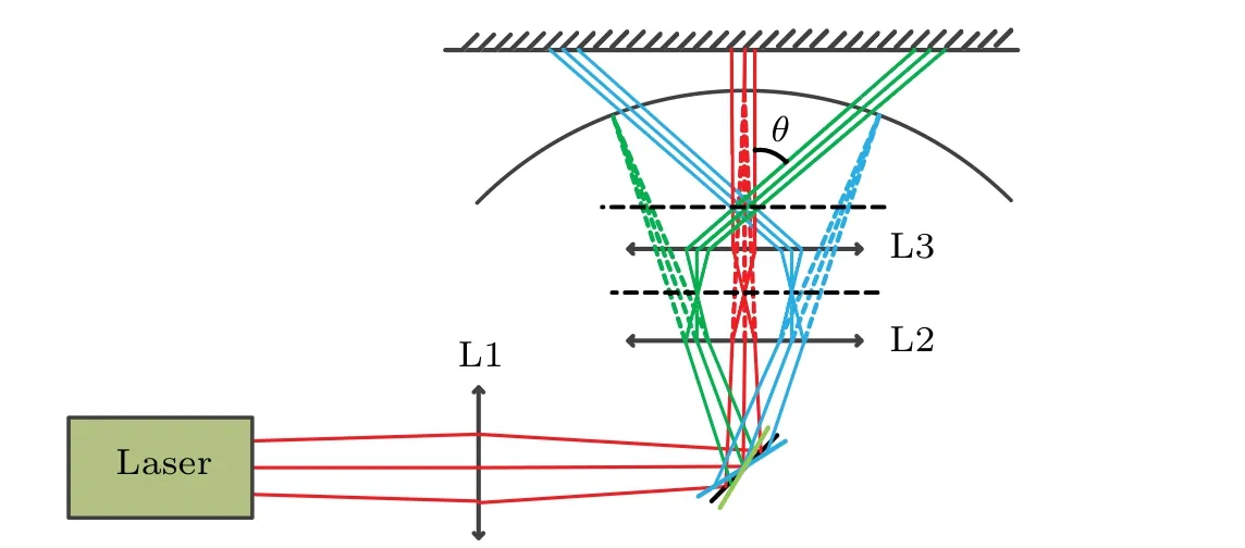
Fig.4. The overall design of the optical system for large field of view scanning of 3D imaging lidar.
The overall design of the optical system for the large field of view scanning of 3D imaging lidar used in this paper is shown in Fig. 4. The system consists of two focusing lenses(L1, L3)and a compensating lens(L2). After pre-expansion,the size of the spot is larger than the effective surface size of the MEMS mirror. In order to focus the laser beams on the effective surface of the MEMS mirror,the beams are focused by the first focusing lens. The center position of the MEMS mirror isA, and the MEMS scanning mirror is controlled by the driving circuit and swings around the center positionAto realize the two-dimensional scanning. After the ref lection of the MEMS mirror, the beam convergence point constitutes a scanning spherical surface,withAas the center of the sphere andRas the radius. If the collimating lens group is placed behind the spherical surface at this time,the requirement of lens aperture will be relatively large,and the aberration correction is quite difficult. Therefore,the L2 is introduced here to transform the formed curved surface into a plane, and the parallel beam is emitted through L3.
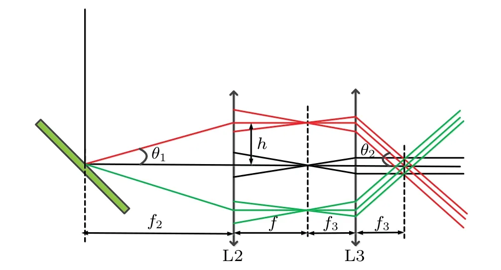
Fig.5.Relationship between scanning angle of MEMS mirror with field of view.
The relationship between the scanning angle of the MEMS scanning mirror with the angle of view can be obtained,as shown in Fig.5. The relationship between the scan angle of MEMS mirror,θ1, and its mechanical rotation angleθis
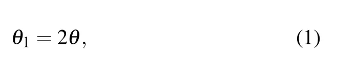
with
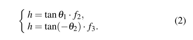
The relationship between the scanning field angleθ2and the scanning angle of the MEMS mirrorθ1can be obtained by solving Eq.(2),and it can be expressed as

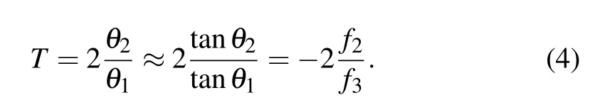
Then the magnificationTof the scan angle can be obtained as
3. Zemax design and performance analysis
According to the theoretical analysis in the previous section, we can get the parameters of each lens as shown in Table 1.
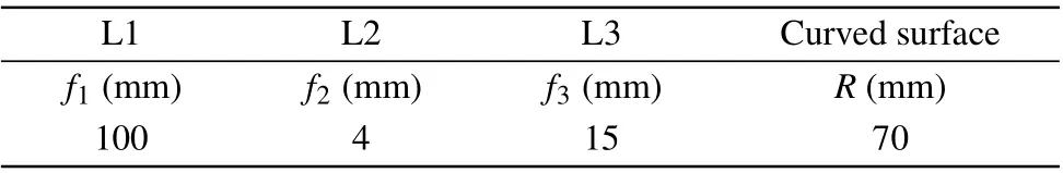
Table 1. Focal length parameters of the designed lenses.
According to the lens parameters in Table 1,three sets of double cemented lenses are selected to obtain the initial structure. In order to compress the beam divergence angle,the introduction of the aspherical coefficient of L3 is optimized,and the final optimization structure is shown in Fig.6.
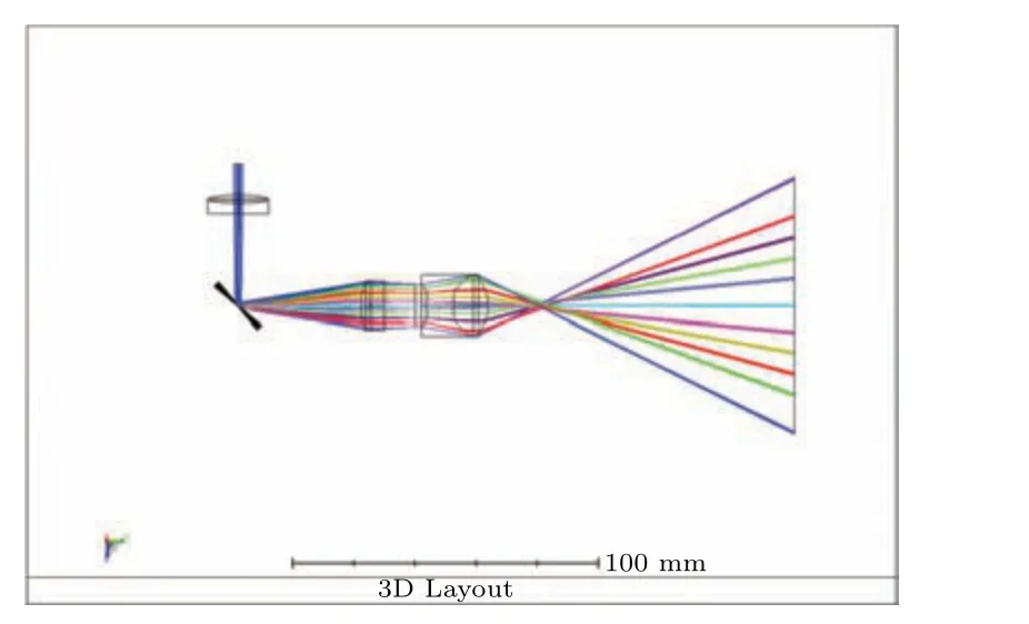
Fig.6. Optimized optical design.
Table 2 shows the data of the final structure. The whole system consists of four parts:focusing lens(L1),MEMS scanning mirror, compensation lens (L2), and exit lens (L3). L1 focuses on the beam so that the beam focuses completely on the MEMS scanning mirror,the light reflected by the MEMS mirror is compensated by L2,the chief ray of the outgoing ray is parallel to the optical axis, and all convergence points of the light are in the same plane. The concentrated light of the equivalent focal plane passes through L3 to achieve parallel light exit,which achieves a wide-range scanning field of view.The maximum angle is 26.5°.
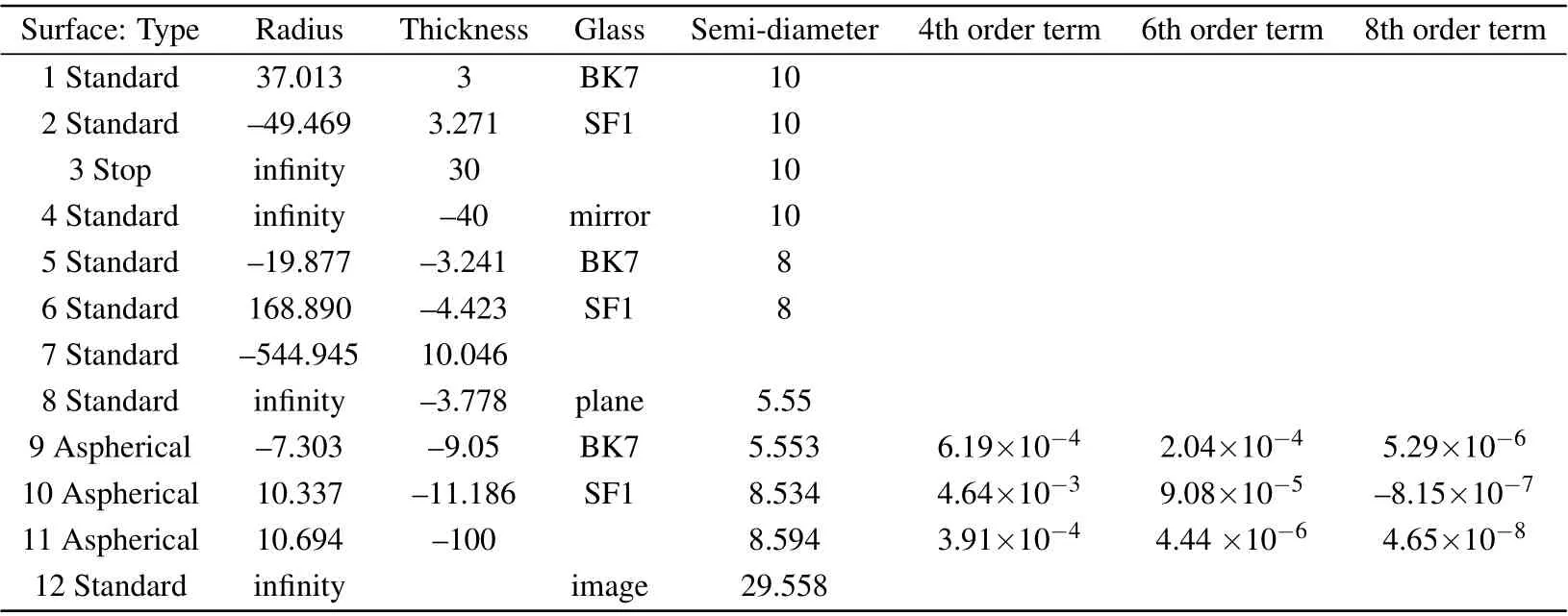
Table 2. Optical parameters of lenses.
Figure 7 is the spot diagram of the system. The spot diagram at a distance of 100 mm from the exit surface shows that the maximum radius of the spot is 0.506 mm and the spot distribution is uniform.The maximum radius of the spot at 100 m is 19 cm,and the diffusion angle is less than 2 mrad. Figure 8 is the geometric encircled energy diagram of an outgoing light spot. Since the outgoing beam is a diffuse spot,and the energy at the centroid of the spot is the strongest, the geometrically encircled energy diagram reflects the energy concentration of the optical system. It can be seen from the figure that 90%of the spot energy is concentrated at the center of mass. The system energy is centrally optimized. Figure 9 is the wavefront diagram of the central light path. The figure shows that the RMS wavefront difference of the outgoing beam is 0.1925 waves,which is less than a quarter wavelength. The outgoing beam spot quality is good.

Fig. 7. The point diagrams of exiting spots in different scanning fields, where the two lines from the upper left to lower right are the cases corresponding to the θ being-4°,-3°,-2°,-1°,0°,1°,2°,3°,and 4°,respectively. (a)The spot diagram at a distance of 100 mm from the exit surface. (b)The spot diagram at a distance of 100 m from the exit surface.
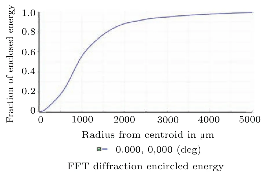
Fig.8. The geometric encircled energy diagram.

Fig.9. The wavefront map.
4. Tolerance analysis
When designing an optical system,it is necessary to consider not only the design index requirements,but also whether the designed lens meets the processing conditions.[26–29]If the system exceeds the processing level, the final result is much different from the design expectation in the later assembly and testing. Therefore,it is necessary to perform tolerance analysis on the system.
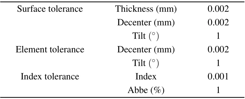
Table 3. Set of tolerances used for Monte Carlo simulation.
Zemax optical design software is used to analyze the tolerance of the designed system. The average value of RMS wavefront is used as the evaluation function standard. The standard value is 0.1925 waves. The set of tolerances are shown in Table 3, and Monte Carlo analysis runs 200 times to obtain the sensitivity data of the optical system. It can be seen from Table 4 that after 200 Monte Carlo simulation experiments,more than 80%of the Monte Carlo samples are greater than 0.1925 waves. The tolerance range given is a relatively loose value. It can be seen that the tolerance of the design is better,and the qualification rate of the lens can be guaranteed in the production process,and the material cost and labor cost are reduced.
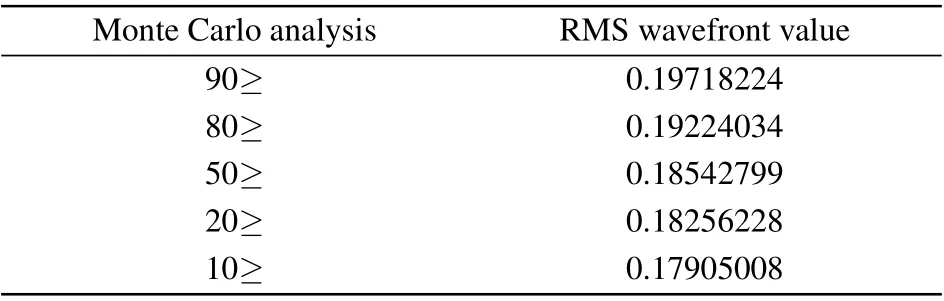
Table 4. Result of Monte Carlo analysis.
5. Conclusion
This paper presents a folded large field of view scanning optical system. Through the theoretical derivation of ray tracing,the structure and parameters of the system are determined.After design and optimization with the Zemax software, the final structure gets good beam collimation and beam expansion performance. The results show that the scanning angle can range from±5 to±26.5°. The scanning field of view is expanded by 5.3 times. The spot diagram at a distance of 100 mm from the exit surface shows that the maximum radius of the spot is 0.506 mm and the spot distribution is uniform.The maximum radius of the spot at 100 m is 19 cm, and the diffusion angle is less than 2 mrad. The energy concentration in the spot range is greater than 90%,the system energy concentration is high, and the parallelism is good. The system overcomes the shortcoming of the small scanning mechanical angle of the MEMS lidar.What is more,it has a compact structure, requires fewer lenses, and is more convenient to adjust.This is very beneficial for the miniaturization of 3D imaging lidar. It has broad application prospects in the field of laser beam collimation and beam expansion.
Acknowledgements
Project supported by the Shenzhen Fundamental Research Program(Grant No.JCYJ2020109150808037),the National Key Scientific Instrument and Equipment Development Projects of China(Grant No.62027823),and the National Natural Science Foundation of China(Grant No.61775048).
杂志排行

Chinese Physics B的其它文章
- Real non-Hermitian energy spectra without any symmetry
- Propagation and modulational instability of Rossby waves in stratified fluids
- Effect of observation time on source identification of diffusion in complex networks
- Topological phase transition in cavity optomechanical system with periodical modulation
- Practical security analysis of continuous-variable quantum key distribution with an unbalanced heterodyne detector
- Photon blockade in a cavity–atom optomechanical system