Drop casting based superhydrophobic and electrically conductive coating for high performance strain sensing
2022-07-26LingWangLishengWuYuqingWangJunchenLuoHuaiguoXueJiefengGao
Ling Wang,Lisheng Wu,Yuqing Wang,Junchen Luo,Huaiguo Xue,Jiefeng Gao
School of Chemistry and Chemical Engineering,Yangzhou University,Yangzhou,Jiangsu,225002,China
Keywords:Drop-casting Contact angle Ag nanoparticles Strain sensor
ABSTRACT Conductive polymer composites (CPCs) strain sensors exhibit promising applications in flexible electronics,people’s health monitoring,etc.It remains a big challenge to develop a simple and cost-effective method to prepare CPCs with high conductivity,corrosion resistance,strong interfacial adhesion and high sensitivity.Here,we propose a facile “drop-casting and fluorination” strategy to fabricate superhydrophobic and highly electrically conductive coating by Ag precursor adsorption onto a commercially available elastic tape,subsequent chemical reduction and final fluorination.The Ag nanoparticles could not only construct the electrically conductive network but also greatly enhance the surface roughness.The contact angle and electrical conductivity of the coating can reach as high as 156° and 126 S/cm,respectively.When used for strain sensing,the superhydrophobic and conductive coating shows a high gauger factor(up to 7631 with the strain from 44%to 50%)and outstanding recyclability.The strain sensor could monitor different body joint motions with the stable and reliable sensing signals even after long time treatment in a corrosive solution.
1.Introduction
Strain sensors have been booming in the past decades,due to their promising applications in health monitoring,flexible electronics,etc[1–4].The sensing mechanism is usually based on the change of the resistance or capacitance during the deformation such as stretching and releasing[5,6].Flexible and stretchable conductive polymer composites(CPCs)are regarded as suitable candidates for strain sensors,in which the polymer possesses the deformation capability while conductive nanofillers are responsible for construction of the conductive network[7–9].In practical applications,the CPC strain sensors may encounter corrosive medium,high moisture and other harsh conditions.Therefore,superhydrophobic CPCs with excellent water proof performance have been recently developed [10–12].In fact,conductive nanofillers such as one dimensional carbon nanotubes (CNTs) and two dimensional reduced graphene oxide (RGO) can be served as the building blocks to achieve high surface roughness [13–15].For example,CNTs and RGO were anchored onto the PU nanofiber surface with the aid of the ultrasonication.The unique core-shell structure,where the polymer nanofibers and conductive nanofillers were served as the core and shell,respectively,could enhance the Young’s modulus and tensile strength,while,to a great extent,maintain the stretchability of the polymer elastomers [16–20].The carbon based nanofillers could also be decorated onto the fiber surface by interfacial hydrogen bonding[21,22].The obtained polymer composites were then usually chemically modified by long chain molecules with low surface energy such as fluorine-containing molecules and polydimethylsiloxane(PDMS)[16,23].
Although multi-step dip-coating is widely used to prepare superhydrophobic CPCs,delicate manipulation is usually required and nanofiller decoration hence the conductivity could not be precisely controlled.In addition,the adsorption of the conductive nanofillers including CNTs,RGO and MXene is easily saturated,which indicates it is difficult to obtain the CPCs with a high electrical conductivity.Spray coating was then developed to tackle these issues[24,25].Li and coworkers prepared a superhydrophobic and electrically conductive coating by a spray-coating method.CNTs and a thermoplastic elastomer were dispersed in cyclohexane to form a uniform solution for spraying,and the obtained coating became superhydrophobic after its surface was swelled by ethanol to produce the hierarchical structure composed of pores and CNT protrusion.When the coating was deposited onto an elastomer substrate,it could be used for strain sensors with the gauge factor up to 80 [26].Nevertheless,much of the solution was diffused into surroundings and did not reach the target substrate during the spraying,leading to not only waster but also the pollution.Moreover,it remains challenging to achieve strong interfacial adhesion between the sprayed materials and the substrate,high conductivity and sensitivity for the spraying coating based strain sensors.
Here,we propose a facile “drop-casting and fluorination” strategy for preparation of the superhydrophobic and highly electrically conductive coating by Ag precursor adsorption onto a commercially available elastic tape,subsequent chemical reduction and final fluorination.Ag nanoparticles (AgNPs) are firmly embedded onto the elastic tape surface,exhibiting excellent interfacial adhesion and hence durability.The contact angle and conductivity of the coating can reach as high as 156°and 126 S/cm,respectively.When used for strain sensing,the superhydrophobic and conductive coating shows a high gauger factor (up to 7631 with the strain from 44% to 50%) and outstanding recyclability.The strain sensor could monitor different body joint motions with the stable and reliable sensing signals even after long time treatment in a corrosive solution.This work provides a low cost and versatile technique to fabricate a multi-functional and robust coating for strain sensing application.
2.Experimental section
2.1.Reagents and materials
Silver trifluoroacetate (STA,AgCF3COO,98%) was purchased from Shanghai Meirel Chemical Technology Co.,Ltd.Hydrazine monohydrate(N2H4·H2O,80%)and anhydrous alcohol were obtained from Sinopharm Chemical Reagent Co.,Ltd.Perfluorooctyltriethoxysilane (TAS) was provided by Shanghai Aladdin Chemical Reagent Co.,Ltd.VHB elastic tape (4910) was purchased from Minnesota-based Minerals and Manufacturing Corporation.Silver glue was purchased from Shenzhen Sinwe New Material Co.,Ltd.
2.2.Fabrication of the drop-casting based strain sensor
Firstly,1 g STA powders were added into 19 g anhydrous ethanol and then the mixture experienced ultrasonication for 30 min to fully dissolve the powders,forming a homogeneous STA solution.Then,the obtained STA solution was dripped evenly onto the surface of one commercial VHB elastic tape (50 mm × 12 mm) with an eyedropper,during which the solution was gradually diffused onto the tape surface.Then,the tape adsorbing the Ag precursor solution was dried thoroughly in an oven to fully evaporate the solvent at 60°C.Note that,the drop casting was repeatedly twice.The dried VHB tape containing the STA was then placed in a diluted hydrazine hydrate (N2H4·H2O) solution with the concentration of 10 wt% for 1 h to reduce the Ag precursor into Ag nanoparticles (AgNPs).The AgNPs anchored tape was rinsed with anhydrous ethanol and fluorinated by immersion in trifluorooctyl triethoxy silane(TAS)solution for 5 h at room temperature.After drying,a superhydrophobic and electrically conductive tape composite(CTC)was obtained.
2.3.Characterization
The surface morphology and cross section thickness of the conductive coating were observed by a field emission scanning electron microscope(FE-SEM,Zeiss Supra55,Germany)with an accelerating voltage of 5 kV.The morphology and elemental mapping of the AgNPs (F-AgNPs) were characterized by using the high-resolution transmission electron microscope (HRTEM,Tecnai G2 F30 Field emission transmission electron microscope).X-ray diffraction (XRD,D8 Advance,Bruker AXS,Germany)analysis was carried out to survey the crystal structure of the AgNPs.The diffraction angle(2θ) was set from 10°to 80°with a speed of 10°min-1.Optical microscopic contact angle (CA) measuring instrument (OCA40,Germany) was used to measure the hydrophobicity of the F-AgNPs coating.The water droplets were 5 μL in size and the contact time was no less than 10 s.Five different positions in the sample surface were chosen for the measurement,and the CA was determined by averaging the five obtained results.The surface conductivity of the coating was measured by using a four-probe resistance meter (RTS-9,Guangzhou Four Probe Technology Co.,Ltd.).For strain sensing tests,the copper wires were tightly bonded to the both ends of the sample with the size of(50 mm×12 mm)using conductive silver glue to ensure good contact of the sample during the test.Universal tensile testing machine was used to apply quantitative strain to the sensor,and at the same time,the resistance variation of the sensor during the stretching and releasing was simultaneously tracked by a digital multimeter.
3.Results and discussion
Fig.1a shows the schematic fabrication process of the superhydrophobic and conductive tape composite(CTC).VHB tape is chosen as the ideal substrate material for flexible strain sensors due to its low cost and thus potential large-scale fabrication,excellent stretchability and strong adhesion property.The silver precursor solution is dripped onto the adhesive surface of VHB tape by a dropper,and the Ag precursor is embedded onto the tape after the solvent evaporation,because the precipitated polymer from the viscous tape surface can wrap AgNPs tightly.Note that the drop-casting is conducted twice to guarantee the sufficient adsorption of the precursor onto the tape.The adsorbed silver precursor is subsequently reduced to AgNPs whose microstructure is shown in the SEM image of Fig.S1.Dense AgNPs and their cluster are observed,and they could not only form the conductive network but also significantly improve the surface roughness.To endow the composite with superhydrophobic property,the TAS molecule with a low surface energy is then grafted on the outer surface of silver nanoparticles.The morphology of the AgNPs coating after TAS modification (F-AgNPs) is displayed in Fig.1b.Compared with the morphology of the AgNPs in Fig.S1,there is almost no change for the F-AgNPs coating.The average particle size of the AgNPs is measured and the column chart of particle size distribution is shown in Fig.S2.The average size of the AgNPs is around 180.3 nm.Besides,the HRTEM image and EDS mapping of the F-AgNPs are also surveyed and displayed in Fig.S3.One thin coating layer on the AgNPs surface can be clearly observed in Fig.S3a.The element mapping images of the F-AgNPs are detected and the elemental distribution of Ag,C,F,O and Si is demonstrated in Figs.S3b–3f,respectively,verifying the uniform modification of the TAS on the AgNPs surface.The cross-sectional SEM image of the conductive elastic tape is shown in Fig.1c,and it is found that the thickness of the conductive F-AgNPs coating layer is approximately 1.36 μm.Besides,it can be clearly observed that the AgNPs cluster is embedded in the adhesive matrix due to the strong adhesive property of the elastic tape,guaranteeing the strong interfacial adhesion.
The influence of fluorination time on the surface water contact angle of the CTC is investigated and shown in Fig.S4.It can be observed that the initial CA of the AgNPs coating is about 142°,and the CA gradually increases with the increase of the fluorination time.The CA finally reaches 156°after 5 h’ fluorination and then levels off with further prolonging the fluorination time.Fig.1d demonstrates the histogram of CAs and electrical conductivity of the AgNPs coating before and after 5 h’fluorination treatment.The coating surface changes from hydrophobic to superhydrophobic and at the same time the electrical conductivity slightly drops from 130 S/cm to 126 S/cm,which may be caused by the thin insulating TAS layer.
The XRD patterns of the pure AgNPs coating and F-AgNPs coating are displayed in Fig.S5.Four diffraction peaks at 38.5°,43.9°,64.3°and 77.1°of F-AgNPs coating are assigned to the (111),(200),(220) and(311)crystal planes of the metallic AgNPs,confirming the face-centered cubic crystalline structure of AgNPs [12,27].Compared with the characteristic peaks of the AgNPs without fluorination,little difference can be observed,suggesting that the fluorination has no influence on the crystalline structure of AgNPs.

Fig.1.(a)Schematic illustration of the fabrication for the superhydrophobic CTC.(b)Surface and(c)cross-sectional SEM images of the F-AgNPs coating.(d)CAs and electrical conductivity of the AgNPs coating before and after fluorination for 5 h.

Fig.2.(a)Influence of pH and(b)time of the acid(pH=1)treatment on the CAs and sliding angles(SAs)of the F-AgNPs coating.Variation of the CAs and SAs of the CTC subject to (c) different tensile strains,(d) ultrasonication in water for 5 h,(e) stretching-releasing for 1000 cycles and (f) bending for 500 cycles.
The obtained CTC shows excellent water proof and corrosion resistance.As shown in Fig.2a,the CAs for the water droplet with the pH ranging from 1 to 13 on the CTC keep larger than 151°.The inset displays the photograph of water droplets sitting on the CTC surface.Clearly,the shape of the droplets remains spherical on the material surface without diffusion into the conductive coating.Based on the Cassie-Baxter model,there is a large amount of air trapped inside the rough surface,and the water droplet is suspended on the solid and air rather than completely wet the rough surface[16].As a result,the water droplet even with a low or high pH value cannot penetrate inside the CTC.To further investigate the stability and durability of the CTC in harsh environment,the CAs,sliding angles (SAs) and conductivity of the sample are measured after immersion in corrosive solution for different time.As shown in Fig.2b,though the CA slightly decreases with the immersion time of the CTC in the hydrochloric acid solution (pH=1),it remains larger than 153°.In addition,the SA of the CTC slightly increases to 7°and the conductivity slightly decreases from 125 S/cm to 120 S/cm(Fig.S6a),even after the sample is floated in the acid solution for 10 h,indicating the excellent anti-corrosive property.
Fig.2c displays the change of the CAs of the CTC under applied strains from 0%to 100%.Though the CA slightly decreases with the increase of strain,it keeps larger than 150°even under 100% strain.The spherical water droplets on the surface of the CTC stretched at different strain can be also observed from the inset in Fig.2c,demonstrating excellent water proof performance of the CTC under mechanical deformation.Although stretching damages the stacking of AgNPs,the generated micro-cracks can,to some extent,improve the surface roughness and hence the superhydrophobicity is maintained during the stretching even with a large strain [15].Moreover,the influence of ultrasonic washing,cyclic stretching-releasing and bending on the CAs and SAs is displayed in Fig.2d-f,respectively.It is found that both the CA and SA of the CTC vary little with the CA of~154°and SA lower than 8°during the 5h ultrasonic washing,1000 cyclic stretching-releasing with a strain of 10% and 500 cyclic bending tests.Furthermore,the durability test exerts little influence on the electrical conductivity of the CTC,and the material conductivity keeps around 120 S/cm even after the series of tests(Figs.S6b–S6d).The morphology of the sensor after multiple strain sensing testing is also observed and shown in Fig.S7.It is found that the AgNPs are still closely connected to each other.These results demonstrate outstanding surface stability and durability for the superhydrophobic and conductive coating,which are mainly attributed to the superb interfacial adhesion between F-AgNPs coating and the adhesive matrix of the elastic VHB tape.
Since the CTC possess excellent stretchability and high conductivity,it shows potential applications in flexible strain sensing.The strain sensing performance of the CTC is shown in Fig.3.Fig.3a displays the relative resistance change (ΔR/R0,ΔR=R-R0,whereR0refers to the original resistance of the CTC andRdenotes the transient resistance of the CTC) of the strain sensor under different tensile strains from 1% to 50%.Clearly,the ΔR/R0increases with the loading of strain and gradually recovers to its initial value during the unloading of the strain,exhibiting outstanding reproducibility for resistance change and hence sensing signals.Meanwhile,the strain sensor shows a low detection limit.Periodic sensing signals are present with the sensing intensity(SI,defined as the maximum ΔR/R0during stretching)of 0.2 even at a low strain of 1%,which is shown in the insert of Fig.3a.Besides,different applied strain would lead to quite different sensing signals with different sensitivity.The larger the applied strain is,the higher the SIbecomes.When the strain is 10%,SIsignificantly increases to 4.9,and further to 670.1 at the strain of 50%.Benefiting from the superb tensile resilience of the elastic tape and sensitive conductive AgNPs network,the CTC sensor demonstrates distinguishable and reliable sensing signals.
As known,stretching could cause the separation of the conductive nanofillers or even the cracks in the conductive pathways and thus the resistance variation,and the sensing performance of the CTC is explained by the tunneling theory.Fig.3b shows the change of ΔR/R0with the strain.It is observed that ΔR/R0tends to increase non-linearly with the strain,and shows sharp growth in the range of 50%–60%.According to the tunneling theory,the tunnel current can be produced in conductive polymer composites,when the distance between conducting particles is about a few nanometers [28,29].The tunneling resistance of the CPC could be computed as follows:
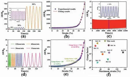
Fig.3.(a)Relative resistance change of the CTC strain sensor under different applied strains.(b)Experimental(point)and fitting(red line)data of the sensing signals of CTC.(c) The 1000 cyclic strain sensing performance of the sensor at a strain of 10%.(d) ΔR/R0 of the CTC sensor under 10% strain at different tensile speed.(e)Sensing sensitivity (gauge factor) of the sensor in different strain ranges.(f) Comparison of the gauge factor of the CTC strain sensor in this work with that of strain sensors based on conductive coatings reported in literatures.
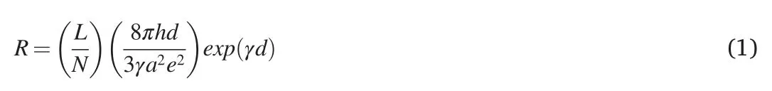
Where the number of conductive particles in a single conductive pathway and the number of conductive paths are denoted asLandN,respectively;hrepresents Planck's constant;d represents the shortest spacing between conducting particles;a2is the effective cross-sectional area;e stands for electron charge;γ=,φ refers to the height of the potential barrier between adjacent particles;The mass of the electron is denoted by m.
Generally,the applied strain is the controlling factor to determine the distance of adjacent conducting particles and can be described by Equation(2),wheres0refers to the original spacing of adjacent particles,b represents a constant,and ε refers to the relative strain applied on the CPC.Accordingly,the relation betweenNandN0(the initial number of conductive pathways) could be described by equation (3),and the resistance change(ΔR/R0) is expressed by equation(4).

By combination of Equation (3) and Equation (4),the relation between ΔR/R0and ε can be finally expressed by Equation(5):
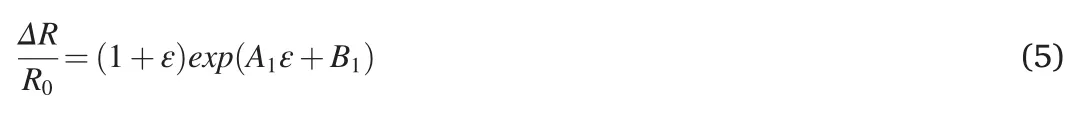
In Fig.3b,the curve of ΔR/R0with ε is fitted by formula(5).It suggests that the fitting curve(red line)fits well with the experimental data(blue dots)with the R2=0.998,whereA1is 0.15078 andB1is-4.69829.
In order to test the repeatability and long-term sensing stability of the flexible strain sensor,the CTC is subjected to cyclic stretching and releasing under 10% strain for more than 1000 cycles (Fig.3c).Obviously,the sensing signals for each cyclic test remains nearly unchanged(see the extracted part from the blue rectangular area of the whole test),and the SIkeeps relatively stable(about 4.9)throughout the cyclic test.It is thus concluded that the damaged conductive network during stretching can completely return to its original state after releasing because of the excellent resilience of the CTC as well as the strong interfacial adhesion.The sensing performance of the CTC under different motion frequency is also studied.Fig.3d displays the variation of the CTC under 10% strain with the strain rates ranging from 120 mm/min to 15 mm/min.Clearly,there is no evident change in the response intensity(namely,the SI),suggesting the sensing independence on the tensile strain rate.Figs.S8a–8d demonstrate the relationship between relative resistance change and strain at different strain rates.Obviously,the resistance variation curve during stretching almost overlaps with that during releasing.Besides,the resistance could nearly recover to its initial value regardless of the tensile frequency.No obvious hysteresis for the strain sensing is observed,which originates from the excellent flexibility and tensile resilience of the CTC.In practical applications,the independence of the sensing behavior on motion frequency is preferable,because it could eliminate the interference of the motion frequency to sensing performance.
Gauge factor(GF,GF=(ΔR/R0)/Δε)as a representative parameter to evaluate the sensing sensitivity of sensors can be calculated by the slope of fitting line as shown in Fig.3e.According to the different responses of ΔR/R0to the strain,the values of GF are 69(0 <ε <20%),639(21 <ε <42%) and 7631 (44 <ε <50%) respectively,showing high sensitivity and distinguishability.The sharp increase of the GF in the strain range of 44 % to 50% may be attributed to the severe damage of the conductive path under larger strain,which will be discussed in the following section.Fig.3f compares the GF and working strain of the CTC based sensor and some conductive coating strain sensors reported[26,30–36].The specific parameters of their sensing behavior are presented in Table S1.It is obvious that the CTC shows a relatively superior sensitivity than most other reported sensors based on conductive coatings.
Due to the highly electrical conductivity,the CTC can be served as a good conductor.As shown in Fig.S9a,the CTC is connected with a LED in a circuit,and the LED light is illuminated at a voltage of 3 V.When a wight of 50 g is put on the CTC surface,the brightness of the LED lamp is unchanged(Fig.S9b),indicating the vertical pressure barely changes the distance between the AgNPs and hence doesn’t influence the conductivity of the CTC.Similarly,when the CTC undergoes bending,the LED lamp can still keep its original brightness,as shown in Fig.S9c.However,the lamp is dimmed when the CTC is stretched as displayed in Fig.S9d.This phenomenon reveals that the electrical conductivity of the CTC is solely sensitive to stretching while other external forces like pressure or bending show little influence on the resistance of the CTC,which is desirable for the sensing reliability for the flexible strain sensors.
Since the sensing mechanism of the CTC sensor is based on the damage and reconstruction of the conductive paths,the surface morphology evolution of the conductive coating is observed by the optical microscope,and the images are displayed in Fig.S10.Fig.S10a displays the optical photograph of the pristine F-AgNPs coating without strain.Since the adhesive surface of elastic tape is fully coated with FAgNPs,forming perfect conductive network and almost no light is allowed to pass through the CTC,showing a completely black color.When a small strain of 10%is applied on the CTC,ultrathin cracks appear in the conductive coating and some light can pass through the cracks,leaving small light spots in the photograph (Fig.S10b).As a result,the relative resistance change of the CTC is slightly increased as displayed in Fig.3a.With the increase of the strain to 30%,the cracks become more and larger,hence more damage to the conductive network occurs,corresponding to a further enhanced resistance of the CTC(Fig.S10c).When the applied strain is further extended to 60%,more and dense light strips are observed (Fig.S10d).Under such strain,a large number of large cracks are formed,resulting in a sharp increase in the resistance.On the other hand,when the strain is gradually released,the F-AgNPs are approaching each other and hence the cracks become narrow and the density of cracks also decreases,as shown in Fig.S10e and Fig.S10f,suggesting the recovery of the conductive networks and hence the recovery of the resistance of the CTC.As the strain is completely released,the conductive network of the F-AgNPs coating almost recovers to its initial state.Therefore,the strain sensing behavior of the CTC is strictly correlated with the transformation of the conductive F-AgNPs networks.
Superhydrophobic conductive coatings with good tensile properties,excellent corrosion resistance and durability have broad application prospects in wearable strain sensors for human body motion monitoring.Fig.4 displays the human motion detection application of the CTC strain sensor.As shown in Fig.4a,when the index finger of the tester is bent from the horizontal state to the vertical state (bending angle:90°),a quick response with the SI>10 is observed.In the process of cyclic bending tests,the sensing curve for each cycle is almost the same,showing excellent repeatability and reliable signals.As shown in Fig.4b,the thumb is bent at 90°and then released with a pause.The sensing curve could remain in a stable state during the bending-releasing cycles.Besides,the sensor also shows a reliable monitoring for the small movement of the little finger bending at about 30°as shown in Fig.4c.When the sensor is used to detect the movement of the back of the hand,stable signals is outputted during the natural bending and release process of the back of the hand as shown in Fig.4d.Fig.4e demonstrates the sensing signals for elbow bending of the CTC.When the elbow is bent at different bending angle,the sensor outputs different sensing signals.For example,the SI(30.5) for elbow bending monitoring with the angle of 90°is larger than that(7.6)with the angle of 30°.Larger bending angle cause more severe damage to the conductive network and hence a higher SI.Other small body movements like gentle walking can also be detected,as shown in Fig.4f.Different body movements correspond to different SI,that is,the sensor shows a very distinguishable detection capability,because the movement of different body parts would cause different strains to the sensor,and thus different sensing signal feedback is harvested.

Fig.4.The sensing performance of CTC in monitoring human movement including cyclic bending motion of (a) the index finger,(b) the thumb,(c) the little finger with a small amplitude,(d) the back of the hand,(e) the elbow and (f) the knee during slow walking.
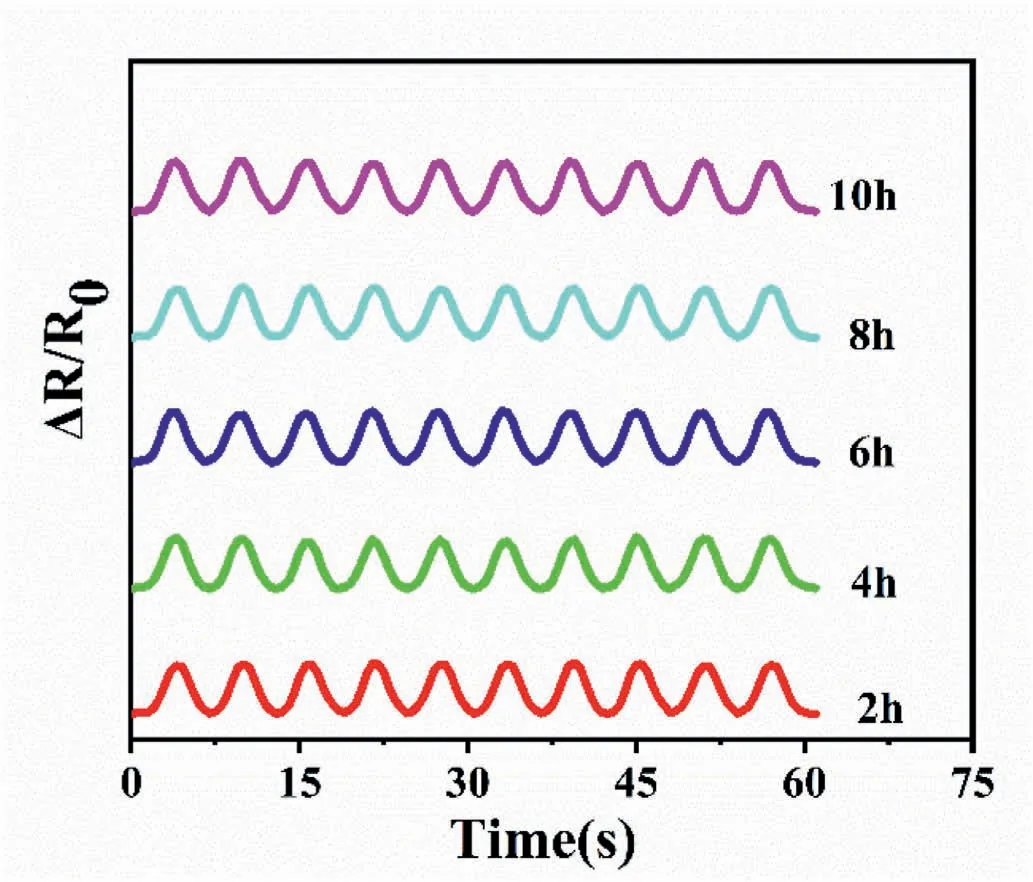
Fig.5.Cyclic index finger bending detected by the CTC sensor after in the acidic solution (pH=1) for different time.
In order to further examine the practical application of the CTC strain sensor in harsh conditions,the CTC after floated in acid solution(pH=1)for different time is used to detect the index finger movement.The corresponding sensing signals are exhibited in Fig.5.It is found that even after the erosion of acid solution for different period of time,the sensing signals are stable and the response curves for index finger bending are almost the same,indicating excellent reliability and durability of the sensor in practical applications.
4.Conclusion
In summary,superhydrophobic and highly electrically conductive FAgNPs coating on a commercially available elastic tape is prepared by “drop-casting and fluorination” method.The contact angle and electrical conductivity of the coating can reach as high as 156°and 126 S/cm,respectively.Due to the strong interfacial adhesion between the conductive F-AgNPs and the adhesive matrix,the CTC exhibits excellent surface stability and durability.The electrical conductivity and superhydrophobicity of the CTC can be maintained even after a series of bending,stretching,ultrasonication washing and even corrosion tests.When applied as a strain sensor,the CTC demonstrates a high gauger factor (up to 7631 with the strain from 44% to 50%) and outstanding recyclability.The strain sensor could monitor different body joint motions with the stable and reliable sensing signals even after the material undergoes long time treatment in an acid solution.
Declaration of competing interest
None.
Acknowledgement
This work was financially supported by Natural Science Foundation of China(No.51873178),the Opening Project of State Key Laboratory of Polymer Materials Engineering(Sichuan University)(No.sklpme2020-4-03),Qing Lan Project of Yangzhou University and Jiangsu Province,High-end Talent Project of Yangzhou University,the Priority Academic Program Development of Jiangsu Higher Education Institutions,Postgraduate Research &Practice Innovation Program of Jiangsu province(No.KYCX18_2364,No.KYCX20_2977) and Outstanding Doctoral Dissertation Fund of Yangzhou University.
Appendix A.Supplementary data
Supplementary data to this article can be found online at https://doi.org/10.1016/j.nanoms.2021.12.005.
杂志排行

Namo Materials Science的其它文章
- Preface of “Trends in Nanomaterials and Nanocomposites:Fundamentals,Modelling and Applications”
--Festschrift in honor of Prof Yiu-Wing Mai's 75th birthday - A comparative study of 85 hyperelastic constitutive models for both unfilled rubber and highly filled rubber nanocomposite material
- On mechanical properties of nanocomposite hydrogels:Searching for superior properties
- Ultra-transparent nanostructured coatings via flow-induced one-step coassembly
- VN nanoparticle-assembled hollow microspheres/N-doped carbon nanofibers:An anode material for superior potassium storage
- Molecular dynamics study on mechanical behaviors of Ti/Ni nanolaminate with a pre-existing void