Preparation of porous polyamide 6(PA6)membrane with copper oxide(CuO) nanoparticles selectively localized at the wall of the pores via reactive extrusion
2022-07-26TianqiLiangJieLiuZhaoyangWeiDeanShi
Tianqi Liang,Jie Liu ,Zhaoyang Wei,Dean Shi
Hubei Collaborative Innovation Center for Advanced Organic Chemical Materials,Ministry-of-Education Key Laboratory for the Green Preparation and Application of Functional Materials,Hubei Key Laboratory of Polymer Materials,School of Materials Science and Engineering,Hubei University,Wuhan,430062,PR China
Keywords:Co-continuous CuO nanoparticles Selective distribution Porous PA6 membrane Catalytic performance
ABSTRACT In this study,CuO nanoparticles are pre-modified with styrene-maleic anhydride copolymers (SMAs) of different molecular weights and MAH contents.Then the pre-modified CuO nanoparticles (CuO-SMAs) are added to the PA6/SEBS (Styrene Ethylene Butylene Styrene copolymer) (40/60 wt/wt) polymer blends with a co-continuous morphology.When SMA3 (MAH=8 wt%,Mn=250000 g/mol) is used to modify CuO nanoparticles,and the grafting degree of SMA3 on the surface of CuO reaches 2.74 wt%,90.71% of the added mCuO-SMA3 nanoparticles can be located at the interface of PA6 and SEBS.A porous PA6 membrane with CuO nanoparticles located at the pore walls can be obtained after the SEBS phase is etched with xylene.The catalytic reaction velocity constant (k) for the reduction of p-nitrophenol in NaBH4 solutions with the PA6/mCuO-SMA3 porous membrane can reach 1.0040 min-1.This work provides a feasible and straightforward method for the preparation of porous polymer membranes with functional nanoparticles located at the wall of the pores.
1.Introduction
In recent years,polymer nanocomposites with functional nanoparticles in a polymer matrix have been widely used in various fields,such as electric conduction [1–4],electromagnetic shielding [5–7],thermal conducting [8–10],flame retardant [11–13],antibacterial [14,15],and catalytic performance[16–18],due to their easy processing and their excellent mechanical and lightweight properties.The primary purpose of this research field is to get the highest efficiency with the lowest content of the functional filler [19–23].
It has been confirmed in many studies that selective distribution of the nanoparticles in one phase or at the phase interface within immiscible polymer blends can effectively reduce the percolation threshold and thus get better performance at a lower additive content [24,25].Wen et al.[26] reported that in polybutylene terephthalate (PBT)/Polycarbonate(PC)/GNPS composites,the distribution of GNPS can be varied by controlling the feeding sequence and blending time.The electrical and thermal conductivity of the composites where GNPS was located in the PBT phase was greater than when the GNPS was distributed randomly.Higher electromagnetic shielding efficiency was also obtained by dispersing copper nanowires in one of the phases of the poly(ethylene-co-methyl acrylate) (EMA)/Ethylene-octene copolymer(EOC)[27].If the functional nanoparticles can be limited to the interface of the two phases,the efficiency of the functional nanoparticles will be further increased [28].Furthermore,if both of the phases within the composites are continuous(the composites should have a co-continuous morphology),the percolation threshold will be further reduced[29,30].Chen et al.[31]successfully dispersed MWCNTs at the interfaces in the co-continuous system formed by polystyrene/polymethyl methacrylate(PS/PMMA),revealed that the percolation threshold of the system was reduced to 0.017 wt%.In addition,a specific phase can be selectively etched away within co-continuous polymer composites in order to form porous polymer membranes [32–34],which can be applied in wastewater treatment [35–49],air purification [50],drug release [51],and antibacterial applications [52–55].
In this work,CuO nanoparticles are introduced into the co-continuous SEBS/PA6 system.SMA with a specified molecular weight and MAH content is chosen to pre-modify these CuO nanoparticles so that they can be selectively located at the interface of PA6 and SEBS.PA6 porous membranes with CuO nanoparticles dispersed at the pore walls are prepared by etching the SEBS phase with xylene.A typical organic pollutant in wastewater,p-nitrophenol,is chosen as the processing sample.The relationship between the contents,distribution states of CuO nanoparticles,and the catalytic efficiencies of the porous PA6 membranes are studied in detail.
2.Material and methods
2.1.Materials
Polyamide 6(PA6-M2800,Mn=20000 g/mol)was obtained from the Guangdong Xinhuimeida Nylon Co.Ltd.Styrene Ethylene Butylene Styrene(SEBS-G1652E)was provided by Kraton polymer research,Belgium.Styrene Maleic Anhydride Copolymer,(SMA1-EF60,MAH=14 wt%,Mn=11500 g/mol)was purchased from Cray Valley USA,LLC,(SMA2-SZ23110,MAH=23 wt%,Mn=110000 g/mol) and (SMA3-SZ08250,MAH=8 wt%,Mn=250000 g/mol) were purchased from Polyscope Polymers B.V.Netherlands,respectively. APTES (γ-aminopropyltriethoxysilane) and Copper oxide nanoparticles with a purity of 99.5%were supplied by Aladdin Ltd.
2.2.Preparation of amino-modi fied CuO (CuO–NH2) nanoparticles
CuO nanoparticles were dried in an oven at 60°C for 24 h.Then 5.0 g dried CuO nanoparticles were ultrasonically dispersed into 125 mL anhydrous ethanol.After that,the suspension was added into a threeneck flask and heated to 75°C in an oil bath.Then,the pre-hydrolyzed APTES solution was added.The volume ratio of pre-hydrolyzed APTES:anhydrous ethanol:water was 20:72:8.The solution was stirred at 300 rpm for 4 h.At the end of the reaction,the resulting products were centrifuged and washed more than three times with anhydrous ethanol to remove the unreacted APTES.Finally,the cleaned CuO–NH2product was dried in an oven at 60°C for 24 h.
2.3.Preparation of CuO nanoparticles grafted with SMA in solution(CuOSMAs)
5.0 g of dried CuO–NH2and 100 mL DMF were added into a threeneck flask and ultrasonically treated for 30 min.At the same time,0.5 g of SMAs was pre-dissolved in 25 mL of DMF at a temperature of 100°C.The SMAs solution was dropped into the CuO–NH2/DMF suspension and reacted at 120°C under nitrogen for 24 h.The stirring speed was 300 rpm.At the end of the reaction,the resulting products were centrifuged and washed with a hot DMF and anhydrous ethanol solution more than three times to remove the unreacted SMAs.Finally,the cleaned CuO-SMAs was dried in an oven at 60°C for 24 h.
2.4.Preparation of CuO nanoparticles via melting grafting SMA (mCuOSMAs)
First,5.0 g dried of CuO–NH2and 45 g SMA(dried at 60°C for 24 h)were melt blended in a Brabender internal mixer at 180°C for 6 min.Then the product was dissolved in 400 mL DMF to remove the unreacted SMAs.Finally,the product was ultrasonically and centrifugally washed with hot DMF and ethanol three times.After that,mCuO-SMAs were dried in a vacuum oven at 60°C for 24 h.
2.5.Composites preparation
SEBS/PA6/CuO-SMA composites were prepared via a two-step process according to our previous method [51,52].First,a masterbatch of SEBS/SMA1/SMA2 (80/12/8 wt ratio) was mixed in a Brabender internal mixer at 180°C.Then,the prepared masterbatch was blended with PA6 and the pre-modified CuO nanoparticles (CuO-SMAs or mCuO-SMAs)at 230°C to obtain the composites with a 4 wt%CuO-SMA nanoparticles.The screw speed was 105 rpm.
2.6.Preparation of porous PA6/CuO-SMAs membrane
The porous PA6/CuO-SMA membranes were prepared by solvent extraction of the SEBS/PA6/CuO-SMA composites.First,the 0.2 mm thick membrane was prepared by hot pressing at 230°C.Then it was placed in a Soxhlet extractor,and xylene was used as the selective extracting solvent.After extraction for 36 h,the weight of the membrane no longer changed.The obtained porous membrane was washed with ethanol and dried in a vacuum oven at 60°C for 12 h.
2.7.Characterization
Fourier transform infrared resonance (FTIR) spectra were recorded from 4000 to 400 cm-1using a Bruker Vertex V70.A small number of CuO-SMAs nanoparticles were mixed with KBr and compressed into pellets for testing.A thermogravimetric analysis was performed on a TGA 1(METTLER TOLEDO)at a heating rate of 10°C min-1from 30 to 800°C under oxygen with a flow rate of 40 mL/min to confirm the grafting degrees of SMA on CuO and the CuO-SMAs contents within the nanocomposites.Field emission scanning electron microscope(FESEM)ZEISS Sigma 500–0627 at an accelerating voltage of 15 kV was used to detect the morphology of the porous membranes.All the membrane samples were cryo-fractured in liquid nitrogen before extraction and then coated with gold.A contact angle tester (JC2000D1) was used to measure the contact angle on the surface of the porous PA6 membranes.
2.8.Catalysis reduction of p-NP
A UV–visible spectrophotometer (TU-1810,Persee,China) was used to determine the catalytic properties of the particles and membranes.0.0028 g nanoparticles or 0.7×0.7 cm membranes were added into an aqueous solution containing 1.5 mL p-NP(2×10⁻⁴M)and 1.5 mL NaBH4(0.012 M).The reaction was performed in a quartz dish.The test was carried out under the same conditions.The experiments were repeated five times to measure the reproducibility.
2.9.Determination of the contents of CuO-SMAs nanoparticles at the interface
Xylene and benzyl alcohol was used as selective solvents for the SEBS and PA6 phase,respectively.It was confirmed that neither of the two solvents could etch away CuO-SMAs nanoparticles located at the interfaces.The contents of the CuO-SMAs nanoparticles dispersed in the PA6 and SEBS phases as well as at the interface were calculated according to the residue weights of the different extracted samples obtained by TGA with equations(1)–(3).
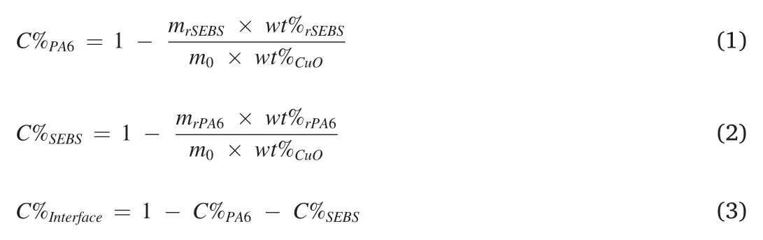
Where,C%PA6andC%SEBSrepresent the distribution percentage of the CuO nanoparticles in the PA6 and SEBS phases,respectively.C%Interfaceis the content of CuO nanoparticles at the interface.m0represents the initial mass of the PA6/SEBS/CuO-SMA composites before etching.wt%CuOis the mass percentage of the CuO nanoparticles in the entire system.mrPA6andmrSEBSare the mass of the PA6 and SEBS phases remaining in the PA6/SEBS/CuO-SMA composites after etching with xylene and benzyl alcohol,respectively.wt%rPA6andwt%rSEBSdenote the mass percentage of the CuO nanoparticles in the etched PA6 and SEBS phases (characterized by TGA).
3.Result and discussion
Selective dispersion of the CuO nanoparticles at the interface of PA6 and SEBS is the key process of preparing the porous PA6 membrane with the nanoparticles located at the pore walls.According to our previous work [52–55],the molecular structures of SMA (molecular weight and MAH content) significantly affects the distribution state of the nanoparticles in the co-continuous PA6/SEBS blends.The first step of this work is to decide the molecular structure of SMA used to modify the CuO nanoparticles.Three kinds of SMAs with different molecular weights and MAH contents(SMA1,SMA2,and SMA3)are used to pre-modify the CuO nanoparticles via solution and melt grafting processes(Scheme 1).FT-IR results shown in Fig.S1a confirm that the SMAs are successfully grafted onto the CuO nanoparticles.The TGA results obtained from the modified nanoparticles(Fig.S1b)revealed that the grafting degrees of CuO-SMA1,CuO-SMA2,and CuO-SMA3 nanoparticles prepared via a solution grafting process are 1.46 wt%,0.96 wt%,and 1.01 wt%,respectively.Furthermore,the grafting degree of SMA3 pre-modified via the melt grafting method(mCuO-SMA3) is 2.74 wt%(Fig.S1b).
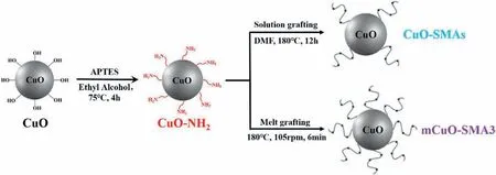
Scheme 1.Preparation method of CuO-SMAs and mCuO-SMA3 nanoparticles.
In order to evaluate the dispersion state of the modified CuO-SMAs,four kinds of CuO-SMAs nanoparticles prepared via a solution and melt modification process are added to the PA6/SEBS (40/60 wt/wt) cocontinuous system (PA6/SEBS/CuO-SMA1,PA6/SEBS/CuO-SMA2,PA6/SEBS/CuO-SMA3,and PA6/SEBS/mCuO-SMA3).If the nanoparticles are located at the interface layer of PA6 and SEBS,they will not be removed during the extraction at either phase via the selective solvent.According to our previous work,the proportions of CuO-SMAs nanoparticles located at the interface region can be calculated from the TGA results(Fig.1)of both the residual PA6 and SEBS phases.Based on the TGA data in Fig.1a-e,theC%PA6andC%SEBSvalues can be obtained via equations (1) and (2).Therefore,the contents of the CuO-SMAs nanoparticles at the interface can be calculated from equation (3) and shown in Fig.1f.SMA3 has proven to be the most effective modifier of the nanoparticles.Over 90% of the modified CuO-SMAs nanoparticles were dispersed at the PA6/SEBS/mCuO-SMA3 system's interface.The SEM micrographs of the residual PA6 phase where the SEBS phase has been etched with xylene shown in Fig.2 indicate the same trend.Compared to the smooth surface of the pure PA6 membrane,CuO nanoparticles were found on the surfaces of all the PA6/CuO-SMAs membranes (Fig.2b–e).Furthermore,the amount of CuO nanoparticles pre-modified with SMA3(Fig.2d and e)are much higher than those premodified with SMA1 (Fig.2b) and SMA2 (Fig.2c).Furthermore,the higher the SMA3 grafting degree is (mCuO-SMA3),the more nanoparticles that can be distributed at the surface of PA6 (Fig.2d and e).These results fit very well with our previous predictions [51,52].In the following part of this paper,the two systems containing CuO-SMA3 nanoparticles (PA6/SEBS/CuO-SMA3 and PA6/SEBS/mCuO-SMA3) are used to prepare the porous PA6 membranes.The catalytic efficiency of the membranes regarding the reduction reaction of the organic pollutant,p-nitrophenol(p-NP),in a NaBH4solution is studied in detail.
It is well known that p-NP can be easily reduced to p-aminophenol(p-AP)by NaBH4in the presence of CuO(Fig.3a).Therefore,if the porous PA6/CuO-SMA3 membranes are submerged into an aqueous solution of p-NP and NaBH4,the concentration of p-NP will decrease,while the concentration of p-AP will increase accordingly.Fig.3b compares the UV absorption spectra of the original p-NP solution and the p-NP solutions containing two kinds of catalytic membranes(PA6/CuO-SMA3 and PA6/mCuO-SMA3) submerged for 10 min.The absorption peak of the nitrogroup at 400 nm weakens (PA6/CuO-SMA3) and even disappears(PA6/mCuO-SMA3).A new absorption peak of the amino-group at 300 nm in both systems confirms that p-NP has been reduced to p-AP.
It can be found in Fig.3b that the higher content of CuO nanoparticles at the pore walls(PA6/mCuO-SMA3),the lower the p-NP concentration will be.The detailed reactive kinetics of the catalytic reaction is also studied.As shown in Figs.S2a and S2b,the variation of UV–vis spectra along with time for PA6/CuO-SMA3 and PA6/mCuO-SMA3 membrane systems are recorded.The peak absorbance value at 400 nm at 0min is labeled as C0,and the corresponding C values are recorded at different reaction times.Both the C/C0~t (Figs.S2c and S2d) and lnC/C0~t(Fig.4a) curves show that the reaction rate for the PA6/mCuO-SMA3 system is much higher than that of the PA6/CuO-SMA3 system.It is reported that the reduction reaction of p-NP via CuO is a first-order reaction in the presence of excess NaBH4[38,44].However,the curve shown in Fig.4a does not fit the first-order rule at the early stage.This may be due to the hydrophobic properties (as shown in Fig.S3) of the PA6 membranes,which needs more time for the solution to saturate all the pores completely.The reaction velocity constant (k) of the two membrane systems is calculated from the lnC/C0~t curve according to the data in the late reaction stages(the conversion rate >85%).The k value for the PA6/mCuO-SMA3 system obtained from Fig.4a is 1.0040min-1,while PA6/CuO-SMA3 is 0.6482min-1.
In general,the k values of the different systems should be proportional to the CuO contents[46,48,49].Due to the aggregation of the CuO nanoparticles,the increments of k are usually slower than those of the CuO contents[45,46].However,according to the results in Fig.4b,when the k value and the CuO content of the PA6/CuO-SMA3 system are normalized as 1.0,the k value of the PA6/mCuO-SMA3 system increases to approximately 50% with only a 17.2% increase of the CuO content.This result is contradictory to all those previously reported.
Fig.S4 illustrates that the k values of pure CuO,CuO-SMA3,and mCuO-SMA3 nanoparticles with the same nanoparticle content (2.8 mg in 3 mL solution) are 1.0960 min-1,0.7484 min-1and 0.4976 min-1,respectively.This result indicates that with increasing degrees of grafting of the SMA3 molecular chains on the surface of the nanoparticles,the catalytic efficiency of the CuO-SMA3 nanoparticles decreases accordingly.Therefore,the abnormal results shown in Fig.4b are due to the exposed areas of the CuO-SMAs nanoparticles in different porous PA6 membranes.

Fig.1.TGA curves of the residual SEBS and PA6 phases,that are etched by xylene or hot benzyl alcohol,respectively.(a)SEBS/PA6(60/40 wt/wt);(b)SEBS/PA6/CuO-SMA1;(c) SEBS/PA6/CuO-SMA2;(d) SEBS/PA6/CuO-SMA3;(e) SEBS/PA6/mCuO-SMA3;and (f) Proportion of the CuO nanoparticles at the interface.
According to our previous work [52–55],there are three dispersion states of the nanoparticles when they are located at the interface.Using PA6/SEBS blends as an example,state I:nanoparticles are located at the interface layer and close to PA6 phase,state II:nanoparticles are located in the middle of the interface layer,and state III:nanoparticles are located at the interface layer and close to SEBS phase(Scheme 2).As the interface layer cannot be dissolved by either of the selective solvents used at the PA6 or SEBS phase,and the dispersion of the nanoparticles is in state I;thus,no nanoparticles are exposed at the pore walls of the PA6 membrane when the SEBS phase is etched by xylene.Meanwhile,the exposed nanoparticle surface areas of state III are much larger than that of state II.
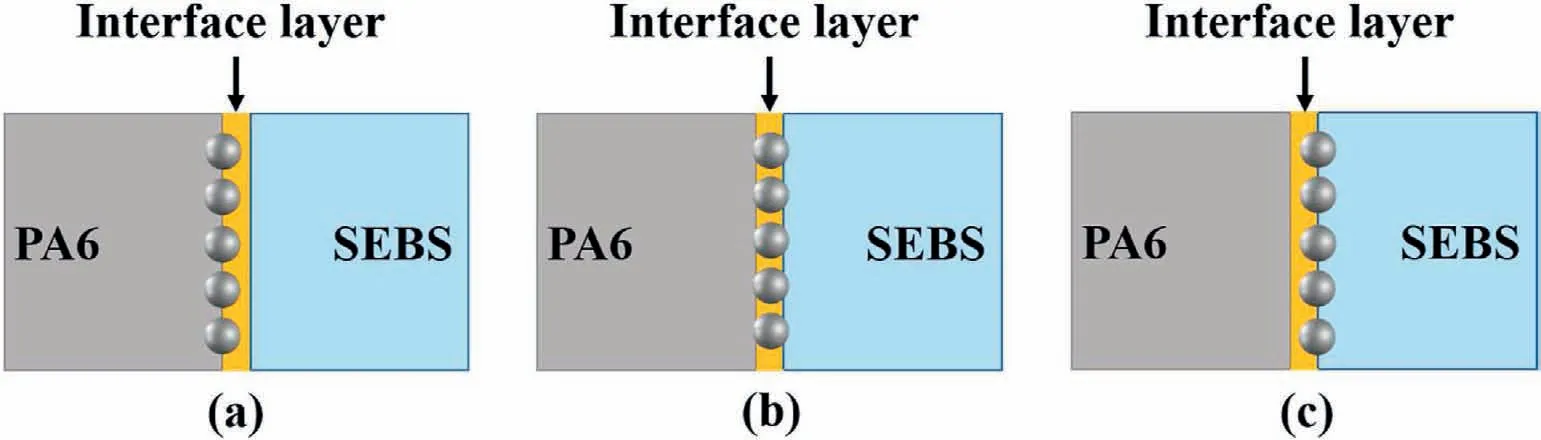
Scheme 2.Different dispersion states of the nanoparticles at the interface of the PA6 and SEBS phases.(a)state I:in the interface layer and close to the PA6 phase;(b)state II:in the middle of the interface layer;(c) state III:in the interface layer and close to the SEBS phase.
In order to explore the differences of the CuO dispersion states within the PA6/SEBS/CuO-SMA3 and PA6/SEBS/mCuO-SMA3 systems,formic acid rather than benzyl alcohol is used to etch the PA6 phase.In this case,if the CuO nanoparticles are dispersed in states I and II,they will also be etched away by formic acid and no CuO nanoparticles can be found in the residual SEBS phase.However,if it is dispersed in state III,although it cannot be found at the surface of the residual SEBS phase,the CuO nanoparticles can be detected near the interface region using an EDS test.As shown in Fig.5a and c,no CuO nanoparticles can be found at the surface of the SEBS phase for both the SEBS/CuO-SMA3 and SEBS/mCuO-SMA3 systems;however,the Cu element can be detected in the SEBS/mCuO-SMA3 system (Fig.5b).This result indicates that mCuOSMA3 nanoparticles are likely dispersed in state III,while the CuOSMA3 nanoparticles are primarily in state II or state I.After taking the statistical analysis of the average size of the CuO nanoparticles exposed at the porous PA6 membranes,the above conclusion can be further confirmed.As shown in Fig.6,the average diameter of PA6/mCuO-SMA3 is 285.4 nm,which is close to the original CuO nanoparticles(293.8 nm),implying that the main body of the nanoparticles have been exposed at the pore's surface.While the data for PA6/CuO-SMA3 indicates a size of 198.6 nm,and is relatively smaller than the diameter of the CuO nanoparticles,indicating that the main part of these nanoparticles is still embedded within the PA6 phase.Therefore,comparing the contents of CuO-SMA3 at the interface layer,their exposed areas are smaller than that of the mCuO-SMA3 nanoparticles.Therefore,the porous PA6/mCuO-SMA3 membrane has a much higher catalytic efficiency than PA6/CuO-SMA3.
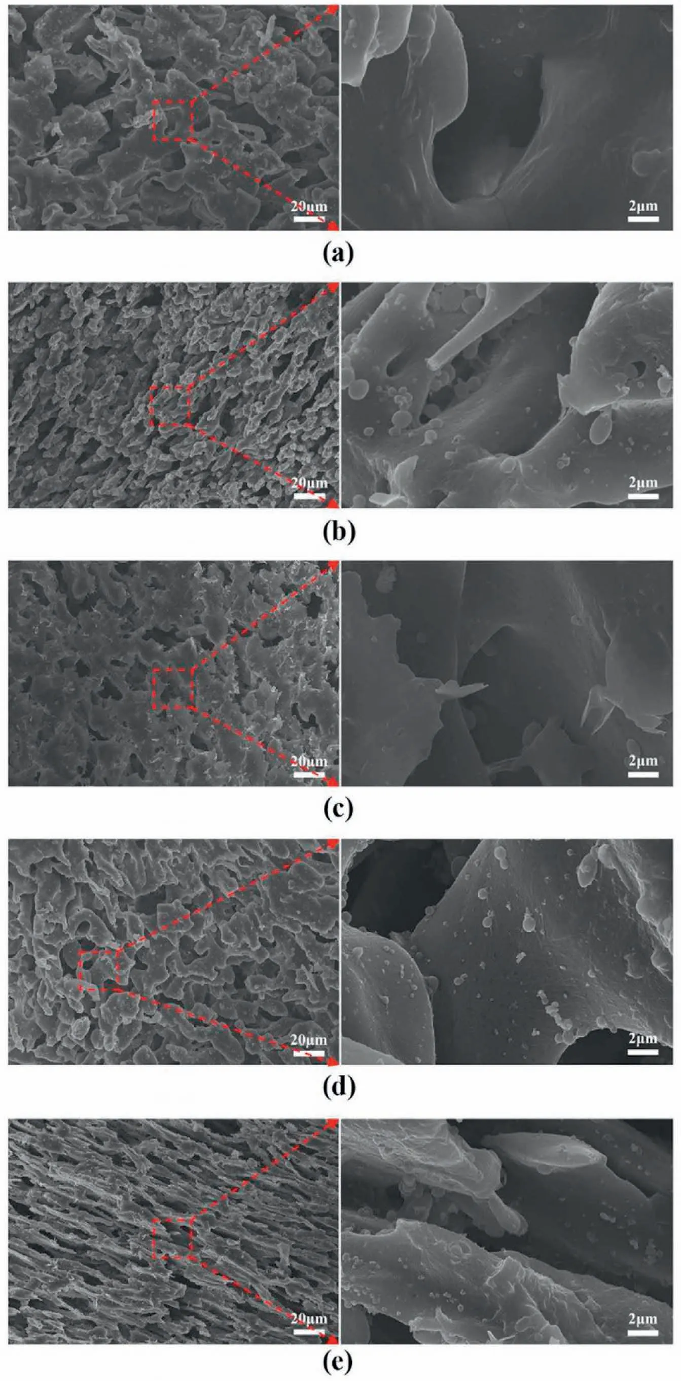
Fig.2.The surface morphology of the porous membranes analyzed by FESEM.(a) Pure PA6 membrane;(b) PA6/CuO-SMA1;(c) PA6/CuO-SMA2;(d) PA6/CuOSMA3;and (e) PA6/mCuO-SMA3.

Fig.3.(a)Schematic diagram of the PA6 catalytic membrane used for the p-NP catalytic reaction process;(b)UV–vis absorption spectra of the original p-NP solution and the p-NP solutions with the PA6/CuO-SMA3 and PA6/mCuO-SMA3 membranes being submerged for 10 min.
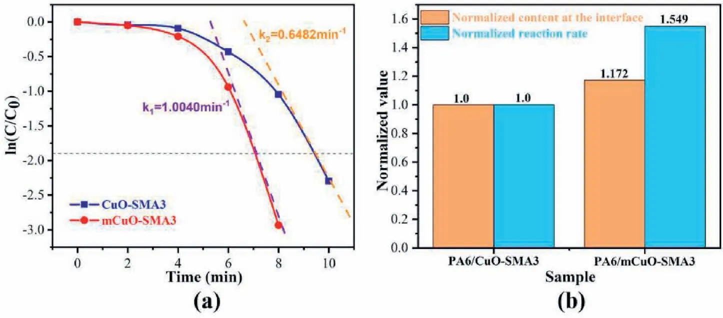
Fig.4.(a)The reaction rate constants of the two kinds of catalyst membranes are obtained when the catalytic rate is 85%.(b)The normalized content at the interface and the normalized reaction rate.
The compatibility of SMA3 and SEBS should be the main driving force.As SMA3 has an 8 wt% of MAH and a very long molecular chain(Mn=250,000 g/mol);thus,making it is more compatible with the SEBS phase.Therefore,the more SMA3 molecular chains grafted onto the surface of CuO (mCuO-SMA3),the higher the possibility of it being dispersed in the SEBS phase (state III),as shown in Scheme 3.
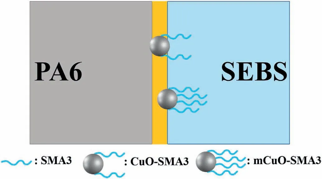
Scheme 3.The compatibility between the SMA3 and SEBS phase makes the CuO nanoparticles more likely to be distributed near the SEBS phase.
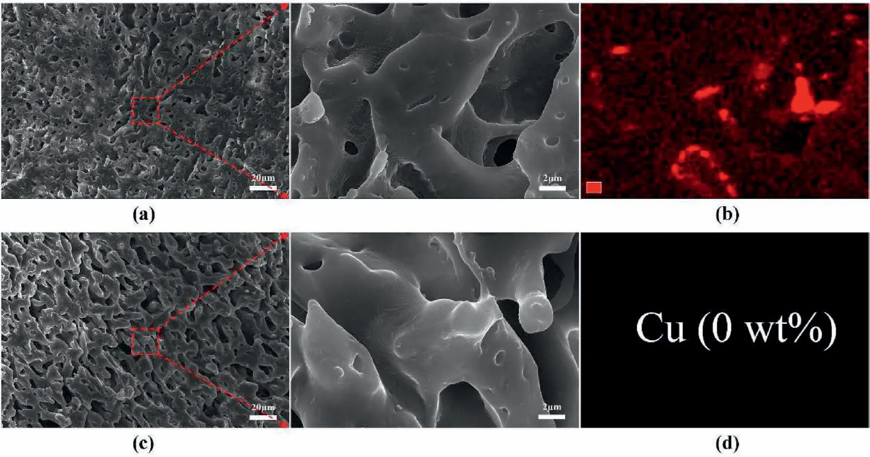
Fig.5.The surface morphology and EDS results of the residual SEBS phase etched by formic acid.(a) and (b) PA6/SEBS/mCuO-SMA3;(c) and (d) PA6/SEBS/CuO-SMA3.
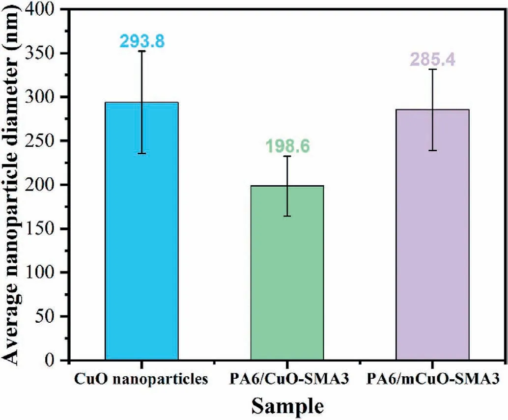
Fig.6.Statistics of the average CuO nanoparticle diameters.
4.Conclusion
The dispersion states of the CuO nanoparticles in co-continuous PA6/SEBS polymer blends can be varied via grafting SMAs with different molecular weights.SMA3,with a relatively high molecular weight and low MAH content,has proven to be the most effective modifier for the dispersion of the nanoparticles at the interface.The higher the grafting degree of SMA3,the more nanoparticles that will be located at the interface.When the grafting degree of SMA3 increases from 1.01 wt%to 2.74 wt%,the proportions of nanoparticles at the interface increases from 77.39% to 90.71%.
The catalytic efficiency also increases with the contents of the CuO nanoparticles at the pore walls of the PA6/CuO-SMAs membranes.However,the catalytic reaction velocity constant (k) is still largely affected by the surface areas of the CuO-SMAs nanoparticles exposed to the solution.When the CuO-SMAs nanoparticles are located at the interface layer and close to the SEBS phase(mCuO-SMA3),more surfaces are exposed after the SEBS is etched;Conversely,if the CuO-SMAs nanoparticles are located at the interface layer and close to the PA6 phase (CuO-SMA3),the exposed surfaces will be significantly reduced.Therefore,the PA6/mCuO-SMA3 membrane has a much better catalytic efficiency than the PA6/CuO-SMA3 system.
In summary,pre-distributing functional nanoparticles at the interface of co-continuous polymer blends and extracting one phase using a selective solvent is an effective way to prepare functional porous polymer membranes with nanoparticles located at the pore walls.The dispersion of the functional nanoparticles at the interface layer close to the extracted phase results in more exposed surface areas of the particles improving the membrane's functionality.
Declaration of competing interest
None
Acknowledgement
We are grateful to the National Natural Science Foundation of China(Grant Nos.51973052,51473047 and 52003077) and Natural Science Foundation of Hubei Province (2019CFB396) for the support of this work.
Appendix A.Supplementary data
Supplementary data to this article can be found online at https://doi.org/10.1016/j.nanoms.2021.09.002.
杂志排行

Namo Materials Science的其它文章
- Preface of “Trends in Nanomaterials and Nanocomposites:Fundamentals,Modelling and Applications”
--Festschrift in honor of Prof Yiu-Wing Mai's 75th birthday - A comparative study of 85 hyperelastic constitutive models for both unfilled rubber and highly filled rubber nanocomposite material
- On mechanical properties of nanocomposite hydrogels:Searching for superior properties
- Ultra-transparent nanostructured coatings via flow-induced one-step coassembly
- VN nanoparticle-assembled hollow microspheres/N-doped carbon nanofibers:An anode material for superior potassium storage
- Molecular dynamics study on mechanical behaviors of Ti/Ni nanolaminate with a pre-existing void