Radiation shielding design of the CFETR polarimeter interferometer and CO2 dispersion interferometer
2022-07-13BoHONG洪博ChanglinLAN兰长林XiaodongPAN潘小东ChaoXU徐超andHaiqingLIU刘海庆
Bo HONG (洪博),Changlin LAN (兰长林),Xiaodong PAN (潘小东),∗,Chao XU (徐超) and Haiqing LIU (刘海庆)
1 School of Nuclear Science and Technology,Lanzhou University,Lanzhou 730000,People’s Republic of China
2 Institute of Plasma Physics,Chinese Academy of Sciences,Hefei 230031,People’s Republic of China
Abstract A three-wave based laser polarimeter/interferometer and a CO2 laser dispersion interferometer are used to determine the electron and current density profiles on a Chinese fusion engineering test reactor (CFETR).Radiation shielding is designed for the combination of polarimeter/interferometer and CO2 dispersion interferometer.Furthermore,neutronics models of the two systems are developed based on the engineering-integrated design of CFETR polarimeter/interferometer and CO2 dispersion interferometer and the major material components of CFETR.The polarimeter/interferometer and CO2 dispersion interferometer’s neutron and photon transport simulations were performed using the Monte Carlo neutral transport code to determine the energy deposition and neutron energy spectrum of the optical mirrors.The energy depositions of the first mirrors on the polarimeter/interferometer are reduced by three orders with the whole shielding.Since the mirrors of CO2 dispersion interferometer are very close to the diagnostic first wall,shielding space is limited and the CO2 dispersion interferometer energy deposition is higher than that of the polarimeter/interferometer.The dose rate after shutdown 106 s in the back-drawer structure has been estimated to be 83 μSv h−1 when the radiation shield is filled in the diagnostic shielding modules,which is below the design threshold of 100 μSv h−1.Radiation shielding design plays a key role in successfully applying polarimeter/interferometer and CO2 dispersive interferometer in CFETR.
Keywords:CFETR,polarimeter interferometer,CO2 dispersion interferometer,shielding design
1.Introduction
A double-pass,radially-viewing,multichannel far-infrared(FIR) polarimeter/interferometer system is under development for current density profile and electron density profile measurements and a short-wavelength infrared CO2dispersion interferometer is under development for higher density without vibration effects in the CFETR tokamak[1-4].The two systems provide comprehensive information on plasma parameters for device protection(e.g.rupture warning),operation control(e.g.electronic density,current density,vertical displacement feedback control),and physical understanding.
A large number of fusion neutrons are generated during CFETR discharge and the diagnostic optics of the polarimeter/interferometer and CO2dispersion interferometer diagnostic are exposed to high-throughput neutrons and photons[5].To ensure the normal and stable operation of the polarimeter/interferometer and CO2dispersion interferometer system during CFETR discharge,it is necessary to evaluate the impact of the radiation environment on the diagnostic system and to design a reasonable shielding structure [6,7].

Figure 1.The general assembly of the graphic design of the EP diagnostic integration.
The design of the CFETR diagnostic system refers to ITER technology and standards.We adopt the minimum,reliable and practical principle in the early stage and select suitable diagnostic systems with multiple functions and less port resource occupancy.The integration of the CFETR diagnostic port is complete,involving three ports,including the E upper window and the E and K equatorial windows[8,9].The general assembly of the graphic design for the equatorial port(EP) diagnostic integration is shown in figure 1 [8].
The polarimeter/interferometer and CO2dispersion interferometer are integrated with the E diagnostic EP plug,containing two diagnostic shielding modules(DSMs)[9,10].The polarimeter/interferometer and the CO2dispersion interferometer are found in the DSM1.Additionally,DSM1 integrates Charge Exchange Recombination Spectroscopy(CXRS) and infrared and visible CCD cameras (IR/CCD),DSM1 structures are shown in figure 2 [9].
This study focuses on the shielding design of the polarimeter/interferometer and CO2dispersion interferometer in the E-DSM1,including optimization of shielding structure and selection of the shielding materials.The neutron energy spectrum and energy deposition of essential mirrors of the polarimeter/interferometer and CO2dispersion interferometer are calculated using the Monte Carlo neutral transport code(MCNP) to evaluate the shielding effect during the shielding design process.In addition,the decay gamma-ray dose rate after the shutdown in the back-drawer region is evaluated[10].
2.Three-dimensional (3D) neutronics model of E-DSM1 and shielding design
2.1.MCNP and calculation model
MCNP is a general-purpose Monte Carlo N-Particle code used for neutron,photon,electron or coupled neutron,photon,and electron transport,which is primarily used to design reactors,radiation shielding,and nuclear protection [7].
For CFETR with 200-MW fusion power,the averaged neutron flux is 1.46×10¹³n cm−2s−1at the equatorial windows,which is close to ITER’s level(2.16×10¹³n cm−2s−1)[5].
The polarimeter/interferometer has nine channels,and the CO2dispersion interferometer has a single channel.The critical components of both are optical mirrors installed in the DSM [10],and the labyrinth structure is designed to shield against neutrons[11].Consequently,each channel has at least two reflective optical mirrors.The mirror is 100 mm in diameter,10 mm thick,and made of molybdenum.In addition,a waveguide was used in each light path to reduce the beam power loss in the propagation process.
DSM employs a variety of low-activated steel and hightemperature resistant materials,the DSM shell body is constructed of 316 stainless steel pieces,and the diagnostic first wall (DFW) is constructed of high temperature resistant tungsten-based composites [12-14].The DSM materials and other materials of the polarimeter/interferometer and CO2dispersion interferometer components used in the calculations are listed in table 1.
The establishment of a 3D neutronics model is divided into the following three steps:

Figure 2.Simplified E-DSM1 model.
Table 1.Materials of the E-DSM1 neutronics model.

Figure 3.(a) 3D neutronics model of E-DSM1,(b) polarimeter/interferometer,CO2 dispersion interferometer waveguides,and optical mirrors.
1) Simplify geometries of channels and systems having less impact on neutronics.
2) Set the material to a uniform solid model.
3) Transform the simplified CAD model into the neutronics model in the MCNP input format.This process uses MCAM software to convert CAD into MCNP model [7,15].
The E-DSM1 3D neutronics model is shown in figure 3.The entire model includes the DSM frame,DFW,waveguide,support structure and optical mirrors.The opening of CXRS and IR/CCD is preserved in the calculation model to ensure the accuracy of the calculation.
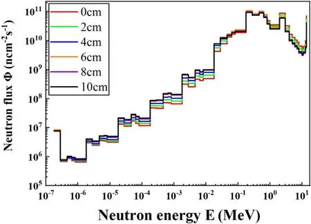
Figure 4.Neutron energy spectrum at the first mirror with various DFW thicknesses.
The nuclear library used for the neutron transport code was Fusion Evaluated Nuclear Data Library FENDL-2.1[16].In this calculation,the neutron source is set as a toroidally symmetrical source with a 14 MeV monoenergetic energy.
2.2.Shielding design
Several materials are added to moderate and absorb the fast neutrons of 14 MeV produced by D-T fusion.Furthermore,due to the limitations of diagnostic space,it is imperative to select a suitable shielding material and structure.
As the first barrier carrying high-temperature plasma and nuclear heat,the DFW is divided into two parts: the heatloading structure of the front section and the rear-end stainless steel support structure.The support structure has been subjected to mechanical analysis so that the thickness cannot be changed.The neutron energy spectrum at the polarimeter/interferometer mirror(black marks in figure 3)is simulated by changing the thickness of the heat-loading structure,where the energy spectrum is shown in figure 4.The neutron flux and neutron energy spectrum are the same at the first mirror when the heat-loading structure is 8 and 10 cm,as shown in figure 4.The shielding capacity did not improve with increasing thickness.Therefore,it is determined that the thickness of DFW comprises an 8 cm heat-loading structure and a 24 cm stainless steel support structure.

Figure 5.(a) Shielding box of a polarimeter/interferometer,(b)shielding box of CO2 dispersive interferometer (shown in purple).
A 4 cm thick shielding box is designed between the DFW and the closure plate to reduce the influence of neutrons entering the DSM from the opening of the DFW of one subsystem to other subsystems.The shielding box structure is shown in figure 5,which is made of 45%W,54%Al,and 1%B4C composite material,containing both fast neutron moderate material,tungsten,and thermal neutron absorption material,boron.In addition,this material interacts with neutrons to produce photons of 3 MeV,which are lower in photon energy compared to other neutron shielding materials [17].
Energy depositions on the CO2dispersion interferometer mirrors,including and excluding the shielding box,are displayed in table 2.The energy deposition on the polarimeter/interferometer mirrors is presented in figure 6.From table 2 and figure 6,it is obvious that the energy deposition of the first mirror of the CO2dispersive interferometer decreased from 3.730 to 0.345 W cm−3,the energy deposition of polarimeter/interferometer mirrors also has a corresponding decrease.The energy depositions of the first mirror for channels 1,2,and 3 are higher than other channels because the openings of the first wall are concentrated in the upper half of the DFW.However,because the second mirror of the CO2dispersive interferometer is closer to the DFW than the first mirror,the energy deposition of the second mirror is higher than that of the first mirror.
Although the shielding scheme described above causes a significant decrease in deposition energy,the neutron energy spectrum in figure 7 shows that the flux of fast neutrons is still at high levels,and the effect of the fast neutron moderate is insufficient.

Figure 6.(a)Comparison of energy deposition of the first mirrors of polarimeter/interferometer with and without shield,(b) comparison of energy deposition of the second mirrors of polarimeter/interferometer with and without shield (horizontal axis corresponds to the channel number of mirrors).
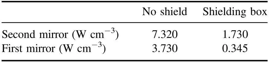
Table 2.Comparison of energy deposition of CO2 dispersion interferometer mirrors with and without shielding box.
Neutrons in the DSM should be sufficiently moderated and absorbed after passing through the DFW and DFW opening.Therefore,70% stainless steel and 30% water were filled in the middle of the DFW and the closure plate to moderate fast neutrons,and a superior neutron absorption material B4C was designed after the closure plate.The structure is shown in figure 8.

Figure 7.Comparison of the neutron energy spectrum of polarimeter/interferometer in the first mirrors with and without shield.

Figure 8.(a) Fast neutron moderate shielding structure,(b) B4C shielding structure.
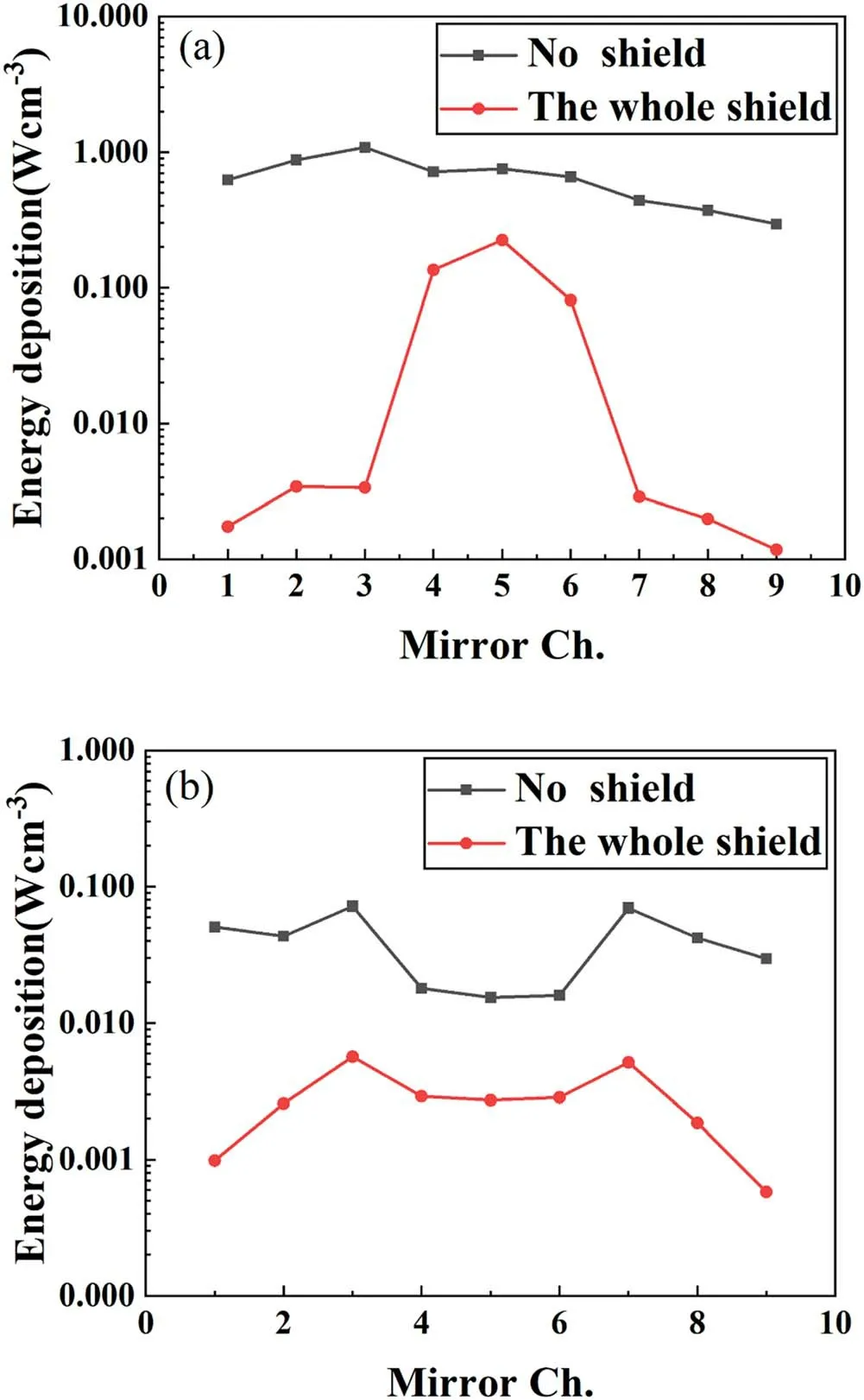
Figure 9.(a)Comparison of energy deposition of the first mirrors of polarimeter/interferometer with and without shield,(b) comparison of energy deposition of the second mirrors of polarimeter/interferometer with and without shield (the horizontal axis corresponds to the channel number of the mirrors).
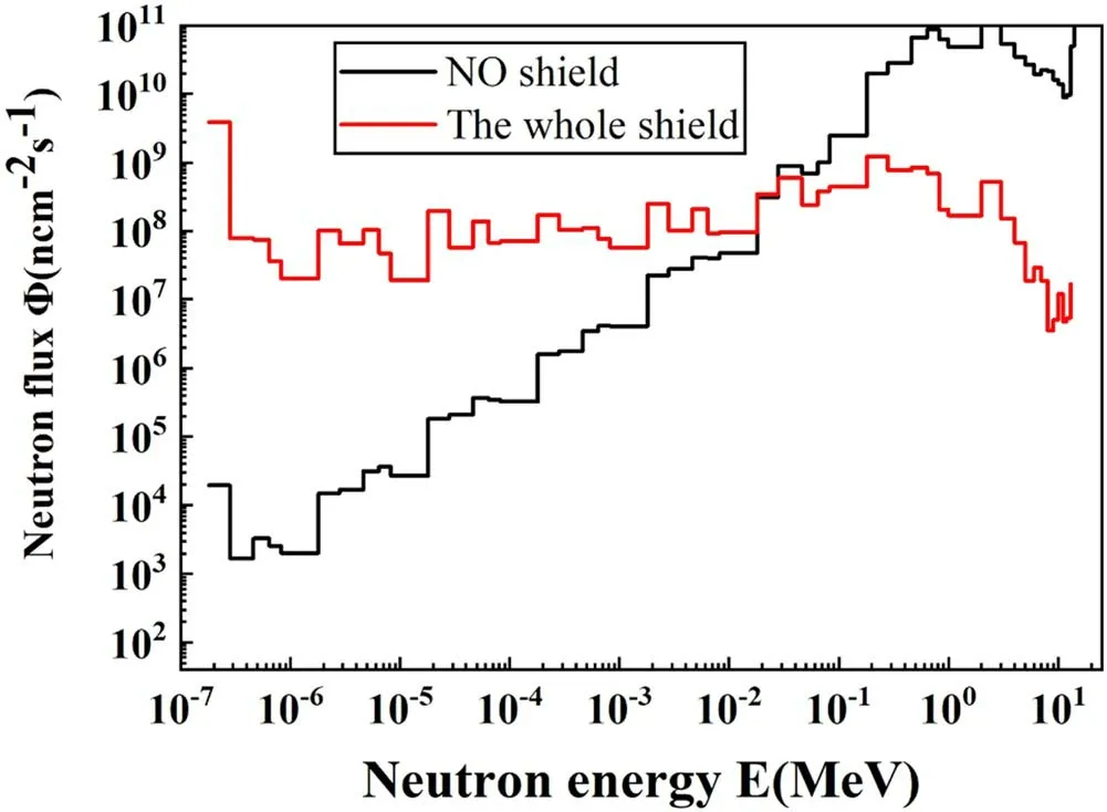
Figure 10.Comparison of the neutron energy spectrum of the first mirror of polarimeter/interferometer with and without shield.

Figure 11.Model for calculating shutdown dose rate.
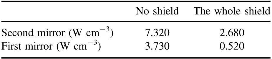
Table 3.Comparison of energy deposition of CO2 dispersion interferometer mirrors with and without shielding structures.
Combined with the several shielding schemes above,the energy deposition in the first and second mirrors when the polarimeter/interferometer is the whole shield is shown in figure 9.The neutrons have been sufficiently moderated,as the neutron energy spectrum at the first mirror is shown in figure 10.Fast neutrons have decreased significantly,and the low-energy neutron flux has increased.The total neutron flux decreased from 1.37×10¹²to 1.13×10¹⁰n cm−2s−1.The maximum energy deposition of the first mirror before shielding is 1.090 W cm-3,and the maximum energy deposition after shielding is 3.36×10⁻³W cm-3,a reduction of three orders.However,the energy depositions of the first mirror for channels 4,5,and 6 are close to that of the sealing plates opening,so the shielding effect of several channels is poor.The CO2dispersion interferometer’s energy deposition when it is the whole shield is shown in table 3,and also decreases significantly.However,because the CO2dispersion interferometer’s optical path design mirrors are very close to the DFW opening,the shielding space is insufficient,resulting in a significantly smaller drop than the polarimeter/interferometer.Compared with table 2,it was found that the energy deposition on the first and second mirrors of the CO2dispersive interferometer increased after adding the neutron moderate shielding structure and absorbent.The main reason is that more secondary photons are generated after adding the shielding material,causing the energy deposition to rise[18].
2.3.Shutdown dose rate
The shielding design described above is primarily intended to reduce the damage caused by neutron and gamma rays to the components of the diagnostic system.However,a qualified shielding design not only protects the components of the diagnostic system,but also ensures the safety of personnel and environmental requirements during the shutdown.The calculation of the shutdown dose rate is particularly important for the maintenance and shielding design of the device.The ITER project requirements call for a design that ensures the shutdown dose rate (SDDR) in areas where in situ maintenance activities are foreseen,be as low as reasonably achievable,and shall not exceed 100 μSv h−1at 106s after shutdown without formal project approval [19].
The shutdown dose rate outside the port plug as shown in figure 11,was calculated by the Rigorous-2-Step (R2S)[20,21] dose calculation program developed by FDS [15].The shutdown dose rate is 83 μSv h−1at 106s after shutdown when the drawer is completely shielded.This value is lower than the design threshold of 100 μSv h−1.
3.Summary
In this study,radiation shielding design was performed for the polarimeter/interferometer and CO2dispersion interferometers of CFETR devices.The shielding effect is evaluated by calculating the diagnostic first and second mirrors of the two diagnostic systems.Furthermore,the energy deposition of the first mirror on the polarimeter/interferometer is reduced by three orders of magnitude when the whole shield is used,showing that the shielding scheme has an excellent shielding effect on the polarimeter/interferometer.However,there is insufficient space for the diagnostic shield equipment because the CO2dispersion interferometer mirrors are very close to the DFW.The energy deposition reduction is less than the polarimeter/interferometer,and the shutdown dose rate can be adjusted to meet the design requirements for fusion reactor maintenance.Future studies will continue to optimize the system based on the radiation shielding design.
Acknowledgments
This work is supported by the National MCF Energy R&D Program of China(Nos.2019YFE03040003 and 2017YFE0301205),also supported by Key Program of Research and Development of Hefei Science Center,CAS(No.2019HSC-KPRD001),and supported in part by the Collaborative Research Program of the Research Institute for Applied Mechanics,Kyushu University.
猜你喜欢
杂志排行

Plasma Science and Technology的其它文章
- Recent progress on the J-TEXT three-wave polarimeter-interferometer
- Design of the stripping unit and the electromagnetic analysis unit for the E//B NPA on HL-2A/2M tokamak
- Space-resolved vacuum-ultraviolet spectroscopy for measuring impurity emission from divertor region of EAST tokamak
- Development of a combined interferometer using millimeter wave solid state source and a far infrared laser on ENN’s XuanLong-50(EXL-50)
- Bench test of interferometer measurement for the Keda Reconnection eXperiment device (KRX)
- Neutron yield measurement system of HL-2A tokamak