High-efficiency unidirectional wavefront manipulation for broadband airborne sound with a planar device
2022-03-12YangTan谭杨BinLiang梁彬andJianchunCheng程建春
Yang Tan(谭杨), Bin Liang(梁彬), and Jianchun Cheng(程建春)
Key Laboratory of Modern Acoustics(Ministry of Education),Institute of Acoustics,Department of Physics,Collaborative Innovation Center of Advanced Microstructures,Nanjing University,Nanjing 210093,China
Keywords: acoustic metamaterials,one-way wavefront manipulation,broadband planar device
1. Introduction
Since the invention of electrical diodes enabling rectifying of current, considerable efforts have been dedicated to research on one-way manipulation of other kinds of energy forms.[1-4]In acoustics, the attempts to break the symmetry in sound propagation began with the emergence of acoustic diode that used nonlinearity to break the limitation of reciprocity, offering the possibility to design novel functional devices that only allowed acoustic wave to pass along one particular direction and may enable special application in various scenarios.[5,6]Later, different mechanisms were proposed for the purpose of further improving the performance of acoustic one-way devices by breaking the spatial symmetry instead of the time reversal symmetry,[7-23]giving rise to different designs featuring broad working bandwidths,[7,8,10,12,13,19,23]high forward transmission efficiencies,[7,8,11,12,14]compact sizes,[9,13,15-17,20,22]planar profiles,[14-16,18,20]etc. In addition, acoustic asymmetric transport inPT-symmetric system[24,25]and topologically protected one-way sound propagation[26,27]have also been investigated. So far, it is still challenging to realize one-way manipulation for broadband airborne sound by using a planar and ultra-lightweight device. More importantly,most of the existing designs are only aiming at producing a different transmission efficiency for wave propagating along opposite directions,which limits their application potential in practical situations where the transmitted waves usually need to be modulated to form various wave fields on demand.
In this study, we propose to realize a highly asymmetric manipulation of the wave field for airborne sound by designing a planar device that works for both normal and oblique incidences within a relatively broad frequency range. The rest of the paper is organized as follows. In Section 2, we introduce the schematic of the proposed model and elucidate the underlying mechanism of our design. Then in Section 3,we give a practical implementation of the proposed model by rationally arranging slits composed of different gases which ensures the low energy loss in forward transmission and light weight of the device. In Section 4, the asymmetric wavefront-steering performance of the resulting device is demonstrated numerically via distinct examples of anomalous refraction, unidirectional acoustic focusing and Bessel beam production,and some discussion on the results is also provided. Finally, a brief summary is given in Section 5.
2. Design of planar device for unidirectional wavefront manipulation
The schematic of our proposed design of the planar device capable of asymmetrically controlling the wavefront for broadband airborne sound is illustrated in Fig.1. Our model is composed of a metasurface(MS)and a layer of homogeneous medium (HM) with judiciously designed system parameters which include the phase gradient dφ/dxof MS and the refractive indexnhof HM (defined asnh=c0/ch, wherechandc0represent the sound speed of HM and the background medium,respectively). The metasurface is assumed to have an acoustic impedance well matching the background medium(chosen as air here for which the mass density isρ0=1.21 kg/m3and sound speed isc0=343 m/s)and low energy loss. We define the positive incidence(PI)as the incidence direction of plane wave that comes from the side of the homogeneous layer,along which the incident sound will be allowed to pass the system,and the incidence from the opposite side as the negative incidence(NI).These two opposite directions are marked by the blue and red arrows in Fig.1,respectively.

Fig. 1. The schematic of the proposed planar unidirectional acoustic transmission device.The propagation trajectories of wave incident from two opposite directions with an incident angle of θi are marked by blue and red arrows.
The mechanism underpinning our designed unidirectional wavefront-steering device can be understood as a broken of symmetry in the propagation trajectory of incident plane wave impinging on two sides of the system with broken spatial symmetry,giving rise to quite different angles of refraction for the PI and NI cases. Due to the broken spatial symmetry of our system,it would be possible to ensure the wave incident from the side of the homogeneous layer at an angle not exceeding the critical angle of the interface,while the reversed wave has an incident angle larger than the critical angle and undergoes a total reflection at the interface. This can be achieved by judiciously choosing the system parameters including the phase profile of the metasurface and the refractive index of the homogeneous medium,and further enables asymmetric manipulation of the transmitted wavefront if the phase gradient provided by the metasurface is controlled locally. Due to the simplicity of our proposed model, the propagation trajectory and critical angles for plane wave in the PI and NI cases can be analytically derived,which offers a fast and precise prediction of the working bandwidth of the resulting one-way device.
According to the generalized Snell’s law,[28]the angles of refraction provided by the metasurface in our designed planar device for the PI and NI cases can be calculated by

whereθiandθtare the angles of incidence and refraction,nhandn0=1 are the refractive indexes of HM and air,k0is the wave number in air, and dφ/dxis the phase gradient of MS.Obviously,when the system parameters in the device are properly chosen such that

the refraction angle is a real value for the PI case, which physically indicates that the acoustic energy of the airborne sound incident normally on the inserted layer of HM can pass through it and then modulated by MS to form the desired pattern on the transmitted side.For the NI case,on the other hand,the refraction angle has nonzero imaginary part since the transverse wave number is larger than the total wave number after passing through MS. Hence the plane wave coming from the opposite side is converted into the evanescent wave in HM and virtually blocked.It should be noted that,although plane wave becomes evanescent in HM for the NI case, HM needs to be thick enough to ensure sufficient attenuation of the evanescent wave alongy-axis. Equation(2)gives the theoretical working bandwidth of such unidirectional control of wavefront that is expected to have high forward transmission efficiency due to the good impedance match and has the capability to work for oblique incidence case, which will be verified via numerical simulations in the following.
3. Implementation of impedance matched metasurface
As a practical implementation of the proposed theoretical model shown in Fig. 1, we choose to build the acoustic metasurface by using multiple cut-through slits that are filled with two noble gases (argon and xenon) on a rigid thin plate.[29]The different regions of air, argon, and xenon can be separated by using polyethylene films (thin enough to be regarded as transparent to acoustic waves), as successfully realized in previous experiment.[6]The sound speed and acoustic impedance of these materials arecXe= 169 m/s,cAr=323 m/s,ZXe=996.1 Pa·s/m,ZAr=576.2 Pa·s/m.By simply modulating the filling ratio of these two gases,the phase shift of transmission wave changes accordingly. Notice that,the good impedance match and low energy loss of natural gases used in this specific design ensures near-unity forward transmission efficiency and well mimics the desired effective parameters to validate our above assumptions.In addition,due to the low dispersion of the gases and the transparency of the thin membrane separating different gases,the resulting device can work in a relatively broad frequency range and have ultralight weight,providing special functionality and flexibility important for practical scenarios.
4. Unidirectional wavefront manipulation
In the following, we will demonstrate the unique unidirectional wavefront-steering functionality of our proposed planar device, which is characterized by the fact that for the PI case the incident wave is manipulated flexibly to form the desired wavefront after being allowed to pass the system and, contrarily, the transmission of NI wave is still forbidden. Three typical examples will be showcased: asymmetric anomalous refraction,high-efficiency convergence of acoustic energy and production of Bessel beam.
4.1. Asymmetric anomalous refraction
For producing the anomalous refraction for plane wave with a wavelength ofλ0incident along the forward direction, one needs to establish a constant phase shift gradient(dφ/dx=2π/d). The schematic of the metasurface is shown in Fig. 2(a). Four slits with one filling with air and others filling with xenon and argon form a period. The slits are separated by rigid walls with width ofwand the width of the filling gases isa, and the width of one period is thusd=4(w+a).The thicknesses of the metasurface and the gases can be readily derived as follows:

wherehAr,irepresents the thickness of argon in theith slit and the relative phase shift of theith slit is(i-1)π/2.
We first consider a simple case of normal incidence of plane wave. In the current study we choose the structural parameters asd=4 cm,w=2 mm,p=8 mm andλ0=3.5 cm such that the first inequality of Eq.(2)is satisfied. The transmittance and phase shift are numerically calculated for each slit and the simulated results are shown in Fig.2(b). It is observed that the slits can be rationally designed to produce precise full-range control of phase shift and near-unity transmission efficiency,as marked by the blue and red dots in the figure, thanks to the well-matched acoustic impedance and low energy loss. On the other hand, the homogeneous medium layer is chosen to be filled with methane gas(cCH4=448 m/s,ZCH4= 294.3 Pa·s/m) with a thickness ofh= 1.7dsuch that the requirement ofch>c0d/λ0given by Eq. (2) is satisfied. Throughout the paper, the numerical simulations are performed by using full-wave simulation based on the finite element method(COMSOL Multiphysics).
We have performed a series of numerical simulations to verify the functionality of producing unidirectional anomalous refraction of the designed device. Typical numerical results are illustrated in Fig. 2(c), which gives the simulated spatial distributions of acoustic pressure at the frequency off0=9800 Hz. The Floquet periodic boundary conditions are applied to the top and bottom boundaries of the system. It is clearly observed that for the NI case, the incident acoustic wave is subject to strong interference and converted into evanescent mode that cannot penetrate into the homogeneous medium layer,resulting in a total reflection on the interface between air and MS.In contrast,the incident plane wave in the PI case normally impinging on the HM is allowed to pass through the system and then leave with a refraction angle of 61°,which agrees well with the prescribed angle given in Eq.(1).It is also noticed that the output waveform is well preserved,which,in addition to the controllable refraction angle, would be highly desirable for the practical application of the resulting one-way devices such as in acoustic communications and imaging.
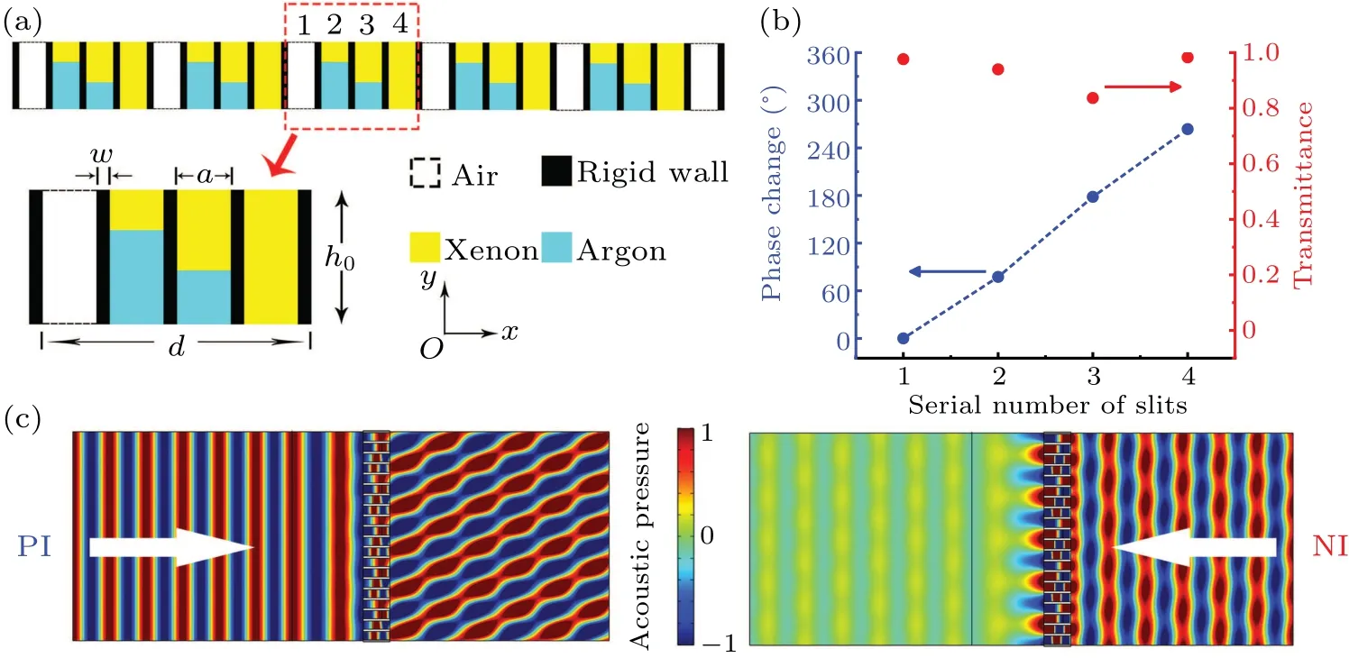
Fig.2. (a)The schematic of the impedance-matching metasurface used in our design. (b)The transmittance(red dots)and phase shift(blue dots)of each slit(i=1,2,3,4). (c)The simulated sound pressure field of PI(left)and NI(right)at a particular frequency of f0=9800 Hz.
Due to the fact that the acoustic signals used in practical applications usually have finite bandwidth, it is necessary to investigate the performance of our design with fixed parameters when the frequency of incident wave deviates fromf0.We plot in Fig. 3(a) and Fig. 3(b) the typical results of simulated sound pressure field for two particular frequencies of 8765 Hz and 10500 Hz,respectively. As shown by the numerical results, for both the cases, the incident acoustic energy is allowed to pass through the device along positive direction while being virtually blocked as the incident direction is reversed,proving the effectiveness of the proposed one-way device. Furthermore, the waveform of the transmitted wave is well maintained,and the refraction angles agree well with the theoretical predictions in Eq.(1),which are about 78°and 55°at 8765 Hz and 10500 Hz,respectively.
For a quantitative evaluation of the unidirectional transmission property of the proposed device within a certain range of driving frequency,we introduce a parameter of contrast ratio,defined as[13]
whereTPIandTNIrefer to the energy transmittance in the PI and NI cases, respectively. Obviously, the value ofRcranges from 0 to 1, and a higherRcindicates that the acoustic transmission in the system is more asymmetric.
For such a specific device with fixed structural parameters, the working bandwidth for normal incidence can be derived by rewriting Eq.(2)as follows:
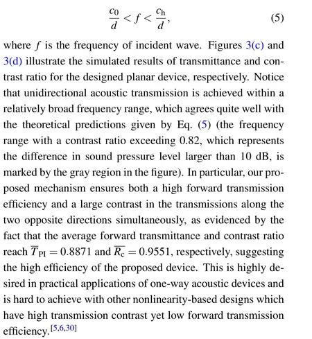
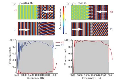
Fig.3. (a)and(b)Simulated spatial distribution of the acoustic pressure at 8675 Hz and 10500 Hz,respectively. (c)Simulated transmittance and(d)contrast ratio as functions of frequency for the PI and NI cases.
Given the fact that the incident angle of incoming wave may varies in practice,it is important to inspect the angular dependence of the one-way performance of our designed device.For a clear view, we plot in Figs. 4(a) and 4(b) the 2D maps of transmittance and contrast ratio obtained from numerical simulations, respectively. An inverted V-shaped zone of high contrast ratio can be clearly observed, proving that our strategy is also capable of working for obliquely incident waves.The effective range of incident angle is closely related to the frequency.For the frequency lower than 9000 Hz,the working angle width is approximately 20°.
We further investigate the formation of such an effective zone.Due to the periodicity of the metasurface with a constant phase shift gradient, the generalized Snell’s law, considering periodic gratings,should be modified as[31]


In fact,m=-2 corresponds to the negative refractive phenomenon and the transmission wave becomes evanescent whileθi <θ(-2)c. As a consequence,acoustic wave is blocked when incident angle is between the two critical angles of different diffraction orders,i.e.,θ(0)c<θi <θ(-2)c. We plot these critical angles in Eqs.(7)and(8)as a function of frequency in Fig.4,where cyan for PI,blue for NI,and solid lines form=0 while dashed lines form=-2. Good agreement between the simulated results of transmittance with the above theoretical analyses can be observed in Figs.4(a)and 4(b),which clearly manifests that asymetric tramission arises from different critical angles for PI and NI caused by the broken spatial symmetry.
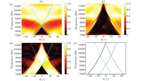
Fig. 4. (a) Transmittance of PI (left), NI (right) and (b) the contrast ratio as a function of frequency and incident angle. (c) Frequency dependence ofthecriticalangles includingc,PI(cyansolid line), (bluesolidline),(cyan dashed line)and (blue dashed line),whichareplotted in(a)and(b)as well forcomparisonwith the simulated results.
4.2. Unidirectional planar focusing lens and axicon
Next,we will demonstrate the capability of the proposed device to manipulate the forward transmitted wavefront more diversely than simply bending its propagation direction while blocking the reversed wave. Considering the significance of energy focusing and beamforming in practical applications such as acoustic ultrasound imaging and therapy, we choose two distinctive examples of unidirectional acoustic focusing and one-way production of Bessel beam to demonstrate the performance of our device in 3D space for normal incidence.In this part,cylindrical coordinate is used withz-axis indicating the incident direction and the slits of MS are numbered alongρ-axis.
4.2.1. Unidirectional planar focusing lens
The schematic of designing a planar focusing lens is illustrated in Fig.5(a). One can readily derive the desired phase shift at an arbitrary point P(ρ) for producing a focus with a focal lengthF,

whereFis the given focal length,λ0is the wavelength of incident wave in air. It should be noticed that,when phase shift expressed as Eq. (9) is used, there exists a critical distance

Here, as an example, we setλ0= 4 cm,h0= 1.03λ0,F=30 cm,w=2 mm,p=8 mm. In addition, helium gas(cHe=970 m/s,ZHe=174 Pa·s/m)is employed as the HM to decreaseρc. The corresponding thickness of Argon in each slit is shown in Fig. 5(b) and the phase shift is conical (red dots)forρ <ρcwhile being hyperboloidal(blue dots)whereρ >ρc.
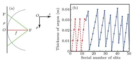
Fig. 5. (a) Schematic diagram of the design of focusing lens. A hyperboloidal phase profile along ρ direction is utilized to focus acoustic plane wave to a single point at a distance F from the device. The blue spherical line with radius F is the desired equiphase surface.(b)The designed thickness of argon in each slit and the corresponding phase shift to be conical(red dots)and hyperboloidal(blue dots),respectively.
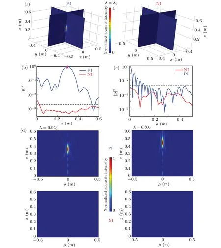
Fig.6. (a)Spatial distribution of the normalized intensity field|p|2 for the PI case(left)and the NI case(right). (b)Longitudinal(along z-axis at ρ =0) and (c) transverse cross-section (along ρ-axis at z=F =0.3 m) intensity profile of PI (blue line) and NI (red line). Logarithmic coordinate for|p|2 is used here to clearly show the difference in order of magnitude. The black dashed line indicates the relative intensity of the incident plane wave and the magenta pentacle in(b)indicates the target focus position. (d)Longitudinal cross-section of the normalized transmission intensity field for the PI case(upper)and the NI case(lower)at λ =0.9λ0 (left)and λ =0.8λ0 (right).
Figure 6(a)shows the typical simulated results of comparison between the normalized spatial distributions of acoustic intensity|p|2in the transmitted region for acoustic normally incident from two opposite sides. The numerical results show that for the PI case, the incident acoustic energy is focused with high efficiency into the prescribed focal region,as characterized by a strong amplification of acoustic intensity at the target region located approximately atz=0.3 m(see Fig.6(b)).For the NI case, contrarily, there is no appreciable enhancement of the acoustic intensity in the transmitted region, suggesting the effective elimination of the reversed wave. For a quantitative estimation of the performance of the designed unidirectional planar focusing lens, the normalized intensity distribution alongz-axis atρ=0 as well as alongρ-axis atz=F=0.3 m are shown in Figs. 6(b) and 6(c). We use the logarithmic coordinate for|p|2here to clearly show the difference of order of magnitude. The intensity of pressure at the focal point is two orders of magnitude higher than the one of incident wave for the PI case while one order lower for the NI case, proving the efficiency of the unidirectional focusing effect. We further investigate the effectiveness of the proposed device when the incident wave lengthλdeviates fromλ0. The transmission fields for the PI and NI cases atλ=0.9λ0andλ=0.8λ0are shown in Fig. 6(d). It is obvious that our device can still effectively focus the incident energy at the predesigned focal region for PI while blocking the sound energy of NI,except for slight variation in the focal length at different frequencies due to the dispersion of MS.
4.2.2. One-way planar axicon
As shown in Fig.7(a),to design a planar acoustic axicon with a base angleβ, the phase shift at the point P(ρ) should be conical and expressed as

To ensure the unidirectional effect, according to Eq. (2), the base angle should satisfy sinβ >nh. Here we setβ=25°and other parameters just the same as those in the above subsection except the phase shift. The corresponding theoretical thickness of argon in each slit according to Eq.(10)is shown in Fig.7(b).

Fig. 7. (a) Schematic diagram of the design of acoustic axicon. The blue cone-like line with base angle β is the desired equiphase surface.(b)The theoretical thickness of argon in each slit of the metasurface.
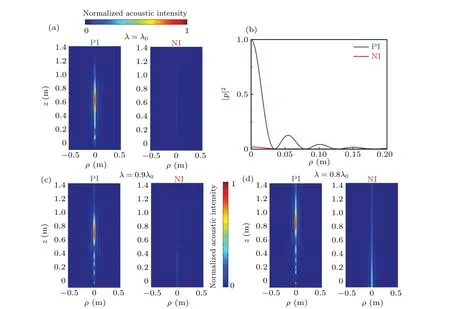
Fig.8. (a)Spatial distribution of the normalized intensity field|p|2 for PI(left)and NI(right). (b)The intensity profile along ρ-axis in the plane located at z=0.7 m. (c)and(d)Longitudinal cross-section of the normalized transmission intensity filed at λ =0.9λ0 and λ =0.8λ0,respectively.
The normalized intensity distribution|p|2in a longitudinal cross-section of PI and NI is shown in Fig.8(a). To quantify the performance of the device, in Fig. 8(b), we plot the transverse cross-section intensity distribution atz=0.7 m for comparison. A non-diffracting Bessel beam propagating with a relatively long distance can be observed for the PI case while the sound pressure is still nearly zero for the NI case,proving the effectiveness of the proposed mechanism, which enables the design of a planar unidirectional axicon. Similarly, simulations are also carried out when the incident wave length changes fromλ0.Typical results of transmission intensity field for incident wave withλ=0.9λ0andλ=0.8λ0are shown in Figs. 8(c) and 8(d), respectively. For both the cases, the non-diffracting Bessel beam for PI can be observed and the acoustic energy for NI is effectively blocked, confirming the broadband characteristic of our device.
5. Conclusion
In summary,we have proposed the design of a planar unidirectional wavefront-steering device for airborne sound by combining a metasurface and a layer of homogeneous medium which can all be implemented by using natural materials.Based on a mechanism that uses the broken spatial symmetry to produce different critical angles along opposite directions, the designed device can work in a relatively broad frequency range for both normal incidence and oblique incidence within a certain angle range, and maintain high contrast ratio and forward transmittance simultaneously. When ensuring the effectiveness of unidirectional transmission, the sound pressure distribution of PI can be manipulated flexibly, which is verified numerically via distinctive examples of unidirectional anomalous refraction,acoustic focusing and Bessel beam production.
Notice that high-efficiency focusing of acoustic energy into the desired spatial region and production of nondiffractive beam are of both fundamental interests and practical significance in various applications ranging from acoustic non-destructive evaluation to ultrasound imaging.It can therefore be expected that the breaking of transmission symmetry of an acoustic focusing lens or an acoustic axicon would be intriguing,which not only overcomes the conventional limitations and may have the potential to revolutionize acoustic technologies in various fields such as acoustic imaging and therapy by effectively blocking the unwanted backscattered waves.
Acknowledgements
Project supported by National Key R&D Program of China (Grant No. 2017YFA0303700), the National Natural Science Foundation of China (Grant Nos. 11634006,11374157, and 81127901), a project funded by the Priority Academic Program Development of Jiangsu Higher Education Institutions,the Innovation Special Zone of National Defense Science and Technology and High-Performance Computing Center of Collaborative Innovation Center of Advanced Microstructures.
猜你喜欢
杂志排行

Chinese Physics B的其它文章
- Measurements of the 107Ag neutron capture cross sections with pulse height weighting technique at the CSNS Back-n facility
- Measuring Loschmidt echo via Floquet engineering in superconducting circuits
- Electronic structure and spin-orbit coupling in ternary transition metal chalcogenides Cu2TlX2(X =Se,Te)
- Characterization of the N-polar GaN film grown on C-plane sapphire and misoriented C-plane sapphire substrates by MOCVD
- Review on typical applications and computational optimizations based on semiclassical methods in strong-field physics
- Quantum partial least squares regression algorithm for multiple correlation problem